


 DBI是一种由MIPI联盟定义的数据传输标准,用于主机与显示设备间的通信。文中详细介绍了四种显示架构,包括各自特点,并详细阐述了TypeA、B、C三种接口的信号描述、写读周期以及不同的颜色编码方案,如3至24位接口对应的色彩数量。此外,还讨论了撕裂效应和显示模块的内部信号处理。
目录
-
- 1 Overview
- 2 Display Architectures
- 3 Interface Signal Description
- 4 Interface Functional
- 5 Tearing Effect
- 6 ColorCoding
-
- 6.1 3-bit Interface
- 6.2 8-bit Interface
-
- 6.2.1 8-bits/pixel (R 3-bit, G 3-bit, B 2-bit), 256 Colors
- 6.2.2 12-bits/pixel (R 4-bit, G 4-bit, B 4-bit), 4,096 Colors
- 6.2.3 16-bits/pixel (R 5-bit, G 6-bit, B 5-bit), 65,536 Colors
- 6.2.4 18-bits/pixel (R 6-bit, G 6-bit, B 6-bit), 262,144 Colors
- 6.2.5 24-bits/pixel (R 8-bit, G 8-bit, B 8-bit), 16,777,216 Colors
- 6.3 9-bit interface
- 6.4 16-bit Interface
-
- 6.4.1 8-bits/pixel (R 3-bit, G 3-bit, B 2-bit), 256 Colors
- 6.4.2 12-bits/pixel (R 4-bit, G 4-bit, B 4-bit), 4,096 Colors
- 6.4.3 16-bits/pixel (R 5-bit, G 6-bit, B 5-bit), 65,536 Colors
- 6.4.4 18-bits/pixel (R 6-bit, G 6-bit, B 6-bit), 262,144 Colors - Option 1
- 6.4.5 18-bits/pixel (R 6-bit, G 6-bit, B 6-bit), 262,144 Colors - Option 2
- 6.4.6 24-bits/pixel (R 8-bit, G 8-bit, B 8-bit), 16,777,216 Colors - Option 1
- 6.4.7 24-bits/pixel (R 8-bit, G 8-bit, B 8-bit), 16,777,216 Colors - Option 2
1 Overview
DBI全称Display Bus Interface, 是用于主机到显示设备的的一种数据传输标准,与之前《06_MIPI打怪升级之DPI》提到的DPI对应。均是由MIPI联盟退出的多媒体相关协议。DBI特点在于需要显示设备内置帧缓冲buffer,一般称之为GRAM,而通过DBI发送一帧数据之后,主机与DBI就可以停止了,显示设备可以根据自行设置的帧率去GRAM中取数据。
参考文档:《MIPI Alliance Standard for Display Bus Interface v2.0》
2 Display Architectures
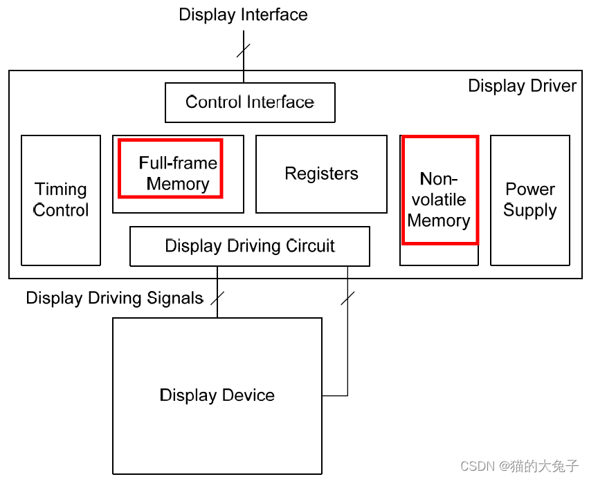
显示模块应基于如下4种显示架构:
根据是否有帧缓存buffer与寄存器配置存储进行区分
- The Type 1 Display Architecture:
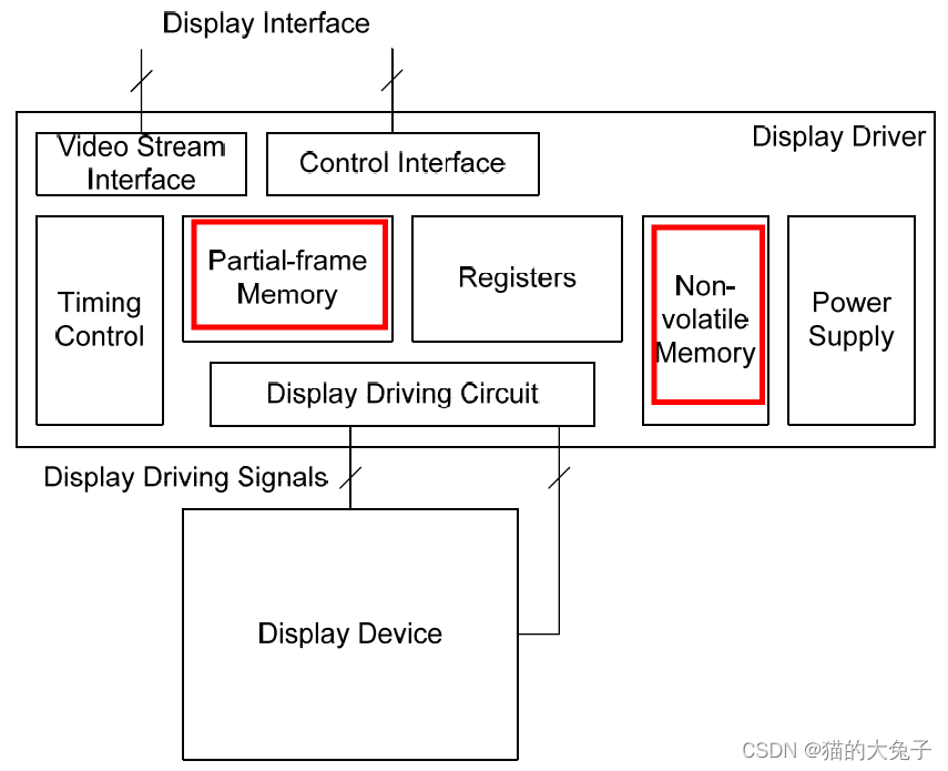
- The Type 2 Display Architecture:
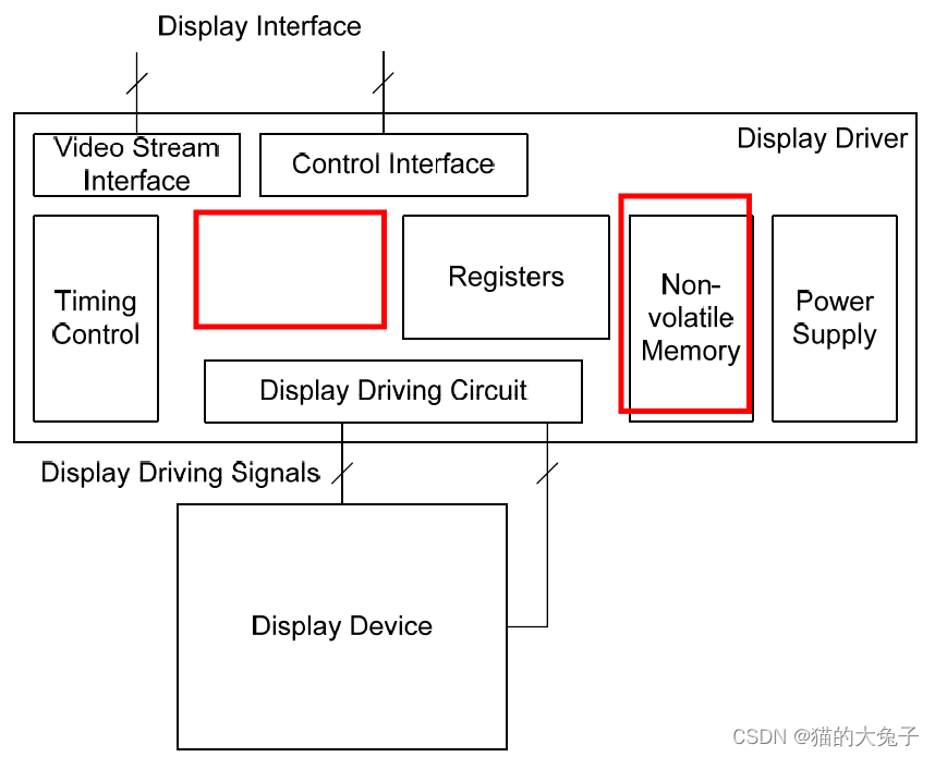
- The Type 3 Display Architecture:
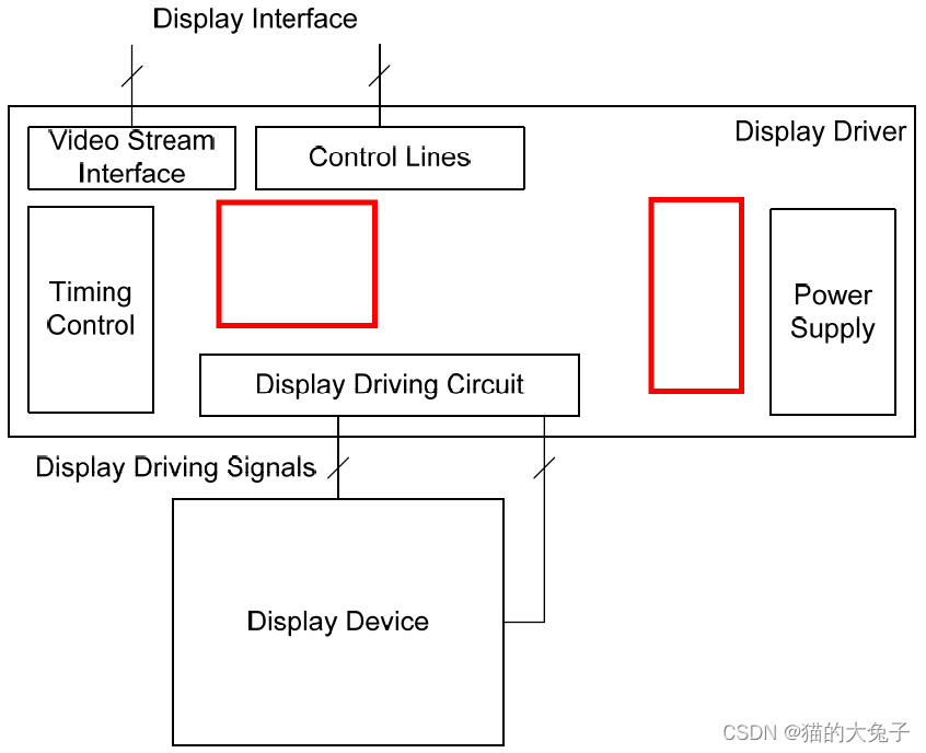
- The Type 4 Display Architecture:
2.1 Type 1 Display Architecture Block Diagram
2.2 Type 2 Display Architecture Block Diagram
2.3 Type 3 Display Architecture Block Diagram
2.4 Type 4 Display Architecture Block Diagram
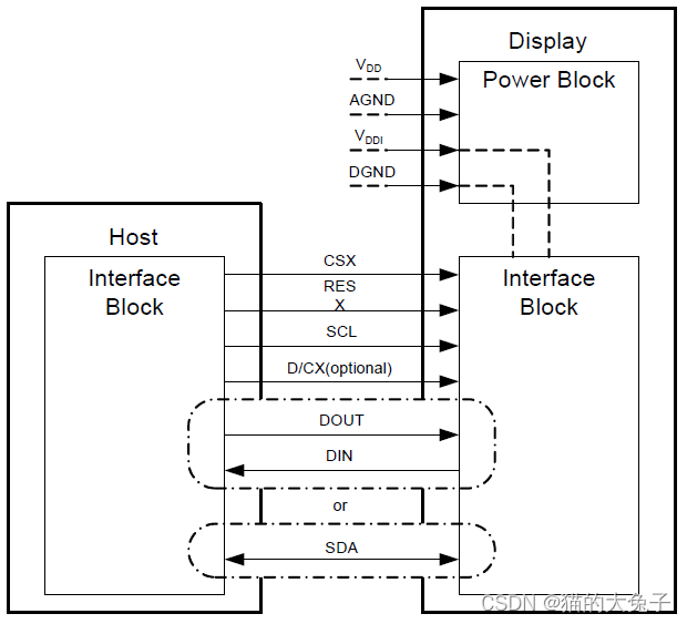
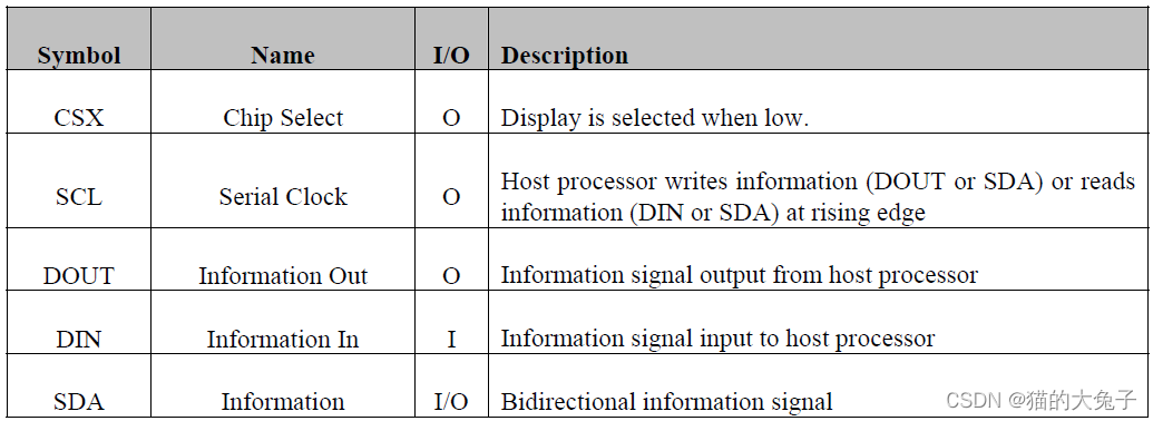
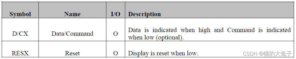
3 Interface Signal Description
在主处理器和显示模块之间有两种类型的信号连接:
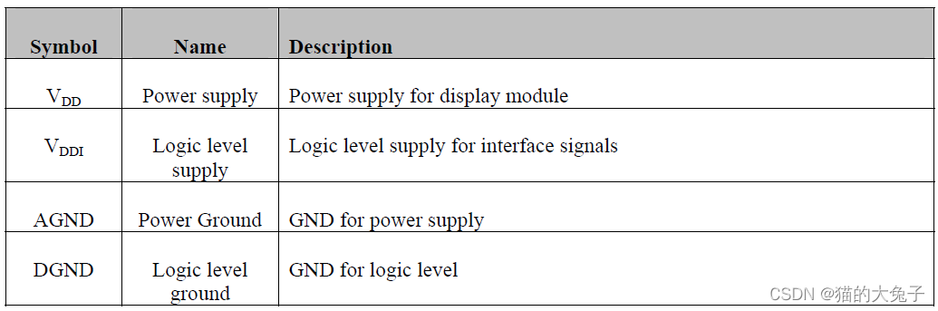
- 电源信号。 电源由主处理器或由主处理器控制的电源管理单元提供。
- 接口信号。 使用接口信号在主处理器和显示模块之间传输像素数据、命令和控制信息。
存在三种类型的 DBI 实现,命名为 A、B 和 C,其差异在于Interface Signals,而Power Supply Signals一致。
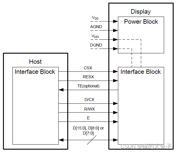
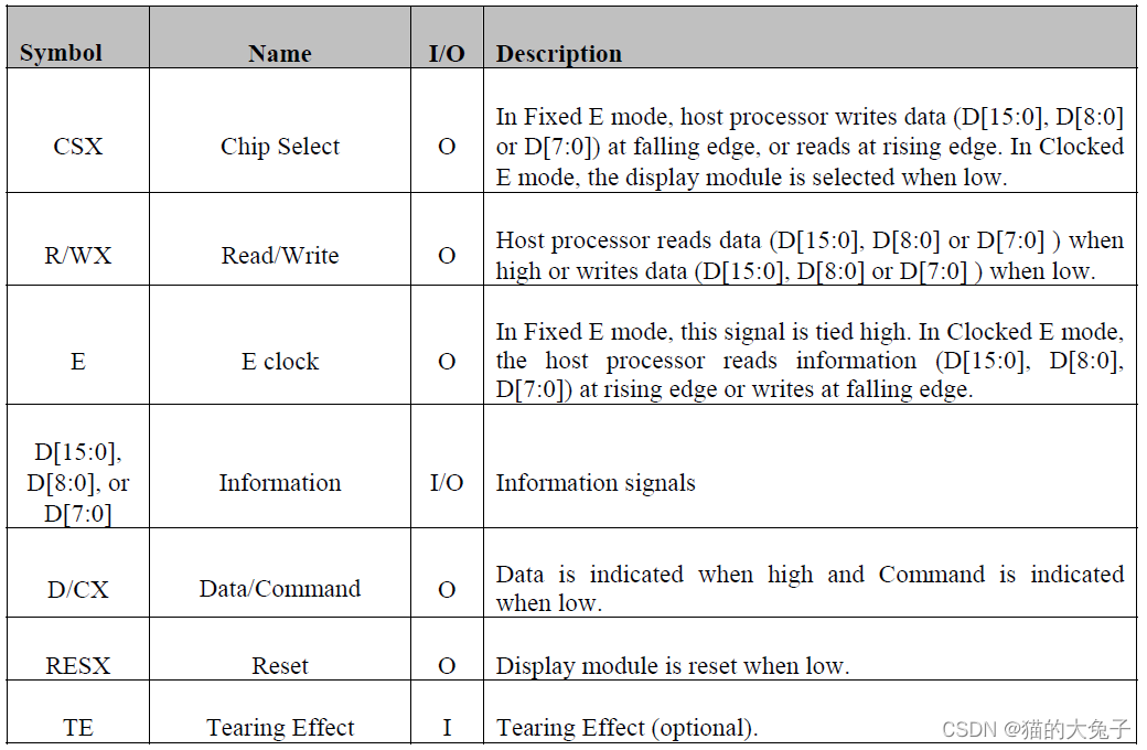
3.1 Type A Interface Block Diagram
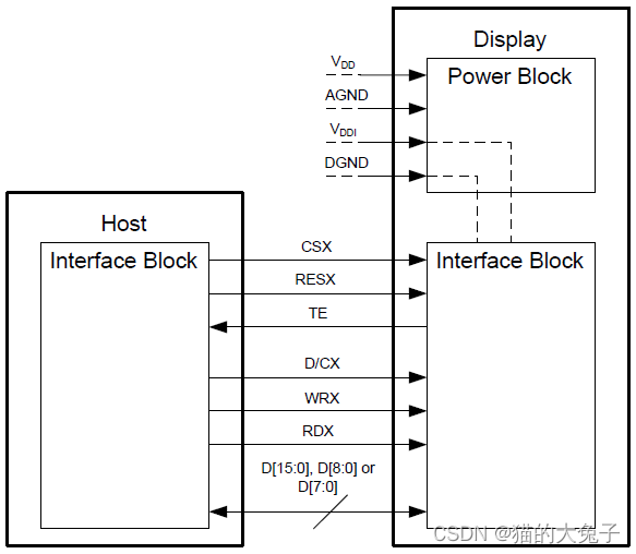
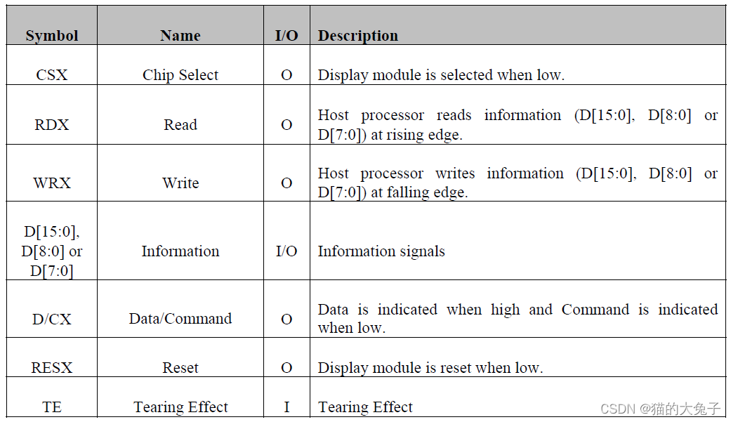
3.2 Type B Interface Block Diagram
3.3 Type C Interface Block Diagram
3.4 Power Supply Signals
4 Interface Functional
4.1 Type A Interface Write and Read Cycles
在写周期期间,主机处理器通过接口将命令或数据写入显示模块。A 类接口支持两种模式:Fixed E 和Clocked E。两种模式都使用 CSX、D/CX、R/WX 和 E 信号以及 所有八个 (D[7:0])、九个 (D[8:0]) 或十六个 (D[15:0]) 信息信号。 当接口上存在命令时,D/CX 被驱动为低电平,当接口上存在数据时,D/CX 被拉高。
在读取周期期间,主机处理器通过接口从显示模块读取数据。 A 型接口支持两种模式:Fixed E 和 Clocked E。两种模式都使用 CSX、D/CX、R/WX 和 E 信号以及所有 8 个 (D[7:0])、9 个 (D[8:0] ) 或十六个 (D[15:0]) 信息信号。 D/CX 在整个读取周期内被驱动为低电平。
Type A Interface - Fixed E Mode Write Cycle:
- CSX 是非同步信号; 它可以停止。
- E 信号在Fixed E 模式下连接高电平。
 最低0.47元/天 解锁文章


 726
726

 被折叠的 条评论
为什么被折叠?
被折叠的 条评论
为什么被折叠?
 到【灌水乐园】发言


