


目录
一、总体系统框图
如下图所示实时图像边缘检测的整体系统框图:
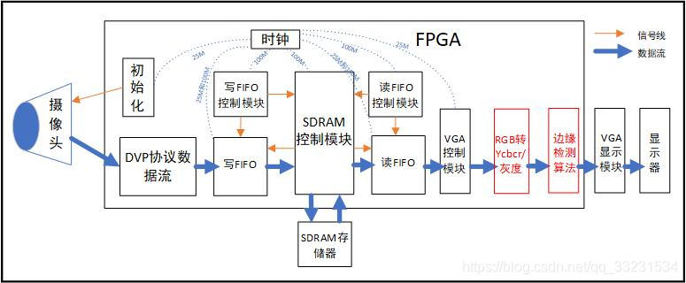
在本人前面博客中有个专栏《OV7670摄像头显示》,本专栏主要是对OV7670摄像头在FPGA平台上实现图像采集和显示。本次对于预想边缘检测的工程是在此代码基础上进行拓展延伸的。如上图所示,其中红色部分就是添加的部分,后边会补充RGB图像转Ycbcr图像格式的博客,此处不再多讲。
二、Sobel边缘检测算法原理
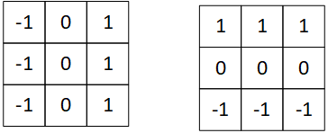
索贝尔算子(Sobel operator)主要用作边缘检测,在技术上,它是一离散性差分算子,用来运算图像亮度函数的灰度之近似值。在图像的任何一点使用此算子,将会产生对应的灰度矢量或是其法矢量。
Sobel算子为:
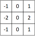
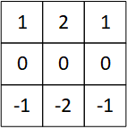
该算子包含两组3x3的矩阵,分别为横向及纵向,将之与图像作平面卷积,即可分别得出横向及纵向的亮度差分近似值。如果以A代表原始图像,Gx及Gy分别代表经横向及纵向边缘检测的图像灰度值,其公式如下:
(1)
(2)
图像的每一个像素的横向及纵向灰度值通过以下公式结合,来计算该点灰度的大小:
(3)
通常,为了提高效率 使用不开平方的近似值:
(4)
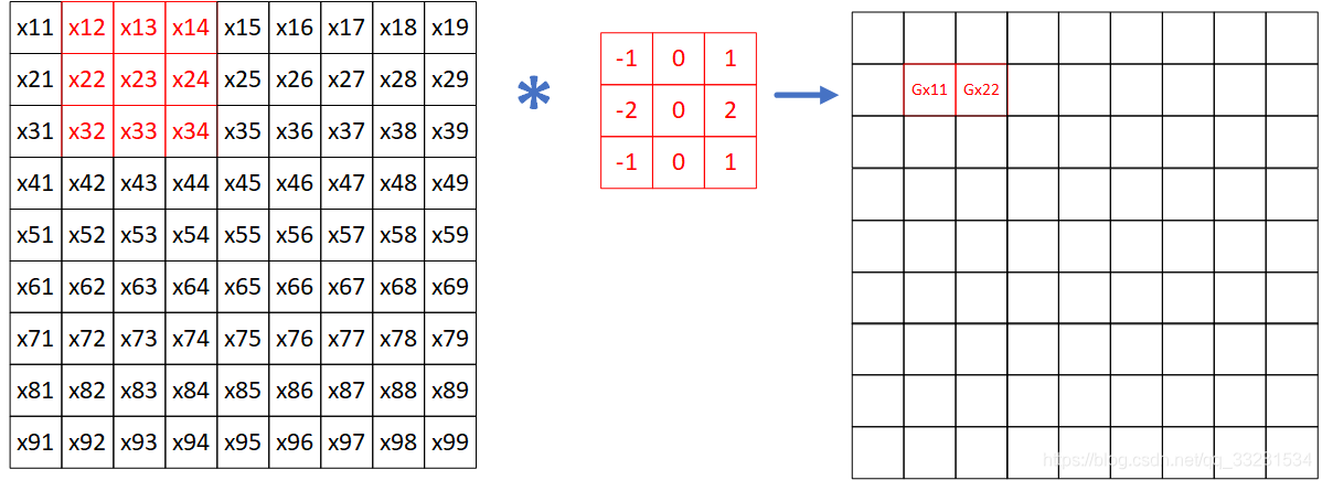
假设9*9图像数据如图所示:

当对(1)式进行运算时,如下

将红色部分对应相乘求和即可:,接着继续滑动求即可如下:
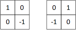
补充:Prewitt算子
Roberts算子:
三、算法实现
本代码仅适用于本系统,了解算法思路略做修改在用在自己系统上。主要用到移位寄存器的使用:
由于本系统的图像是640*480,每个像素是8位的灰度图像,因此寄存器使用的数据宽度是8位,因为矩阵是3*3的,tap需要2个,再加上输入可组成3行数据流水线输出,组成矩阵进行运算,其原理如下:

这样三级流水线可对图像三行数据进行操作,若要实现3*3矩阵操作,可对上述三行数据进行三级寄存器操作,就可以操作3*3的矩阵了,就不在赘述了。移位寄存器IP设置如下

四、代码
1、RGB转Ycbcr代码
// 24位RGB转Ycbcr
module rgb_ycbcr(
	input			clk						,
	input			rst_n					,
	input	[23:0]	i_VGA_RGB				,
	input			i_VGA_HS				,
	input			i_VGA_VS				,
	input			i_VGA_BLK				,
	input			i_data_en				,
	input	[9:0]	i_hcount				,
	input	[9:0]	i_vcount				,

	output	[23:0]	o_ycrcb					,
	output			o_VGA_HS				,
	output			o_VGA_VS				,
	output			o_VGA_BLK				,
	output			o_data_en				,
	output	[9:0]	o_hcount				,
	output	[9:0]	o_vcount
	);


	//浮点数的定点化,乘256
	localparam y_r = 10'd66		;//y通道r前面系数,0.257定点数
	localparam y_g = 10'd144	;//y通道g前面系数,0.564定点数
	localparam y_b = 10'd25		;//y通道b前面系数,0.098定点数
	localparam y_c = 13'd4096	;//y通道常数前面系数,16定点数

	localparam cb_r = 10'd38	;//cb通道r前面系数,0.148定点数
	localparam cb_g = 10'd74	;//cb通道g前面系数,0.291定点数
	localparam cb_b = 10'd112	;//cb通道b前面系数,0.439定点数
	localparam cb_c = 16'd32768	;//cb通道常数前面系数,128定点数

	localparam cr_r = cb_b		;//cr通道r前面系数,0.439定点数
	localparam cr_g = 10'd94	;//cr通道g前面系数,0.368定点数
	localparam cr_b = 10'd18	;//cr通道b前面系数,0.071定点数
	localparam cr_c = cb_c		;//cr通道常数前面系数,128定点数

	//第一级流水线
	reg [17:0]	mult_r_for_y	;
	reg [17:0]	mult_g_for_y	;
	reg [17:0]	mult_b_for_y	;

	reg [17:0]	mult_r_for_cb	;
	reg [17:0]	mult_g_for_cb	;
	reg [17:0]	mult_b_for_cb	;

	reg [17:0]	mult_r_for_cr	;
	reg [17:0]	mult_g_for_cr	;
	reg [17:0]	mult_b_for_cr	;

	//第二级流水线
	reg [17:0]	add_y_0		;
	reg [17:0]	add_y_1		;

	reg [17:0]	add_cb_0	;
	reg [17:0]	add_cb_1	;

	reg [17:0]	add_cr_0	;
	reg [17:0]	add_cr_1	;

	//第三极流水线
	wire 	sian_cb	;
	wire 	sian_cr	;

	reg [17:0]	result_y	;
	reg [17:0]	result_cb	;
	reg [17:0]	result_cr	;


	reg [9:0]	y_temp 		;
	reg [9:0]	cb_temp		;
	reg [9:0]	cr_temp		;

	wire [7:0]	o_y 		;
	wire [7:0]	o_cb 		;
	wire [7:0]	o_cr 		;

	//延时3个时钟周期
	reg 	i_VGA_HS_1		;
	reg 	i_VGA_VS_1		;
	reg 	i_VGA_BLK_1		;
	reg 	i_data_en_1		;

	reg 	i_VGA_HS_2		;
	reg 	i_VGA_VS_2		;
	reg 	i_VGA_BLK_2		;
	reg 	i_data_en_2		;

	reg 	i_VGA_HS_3		;
	reg 	i_VGA_VS_3		;
	reg 	i_VGA_BLK_3		;
	reg 	i_data_en_3		;

	reg	[9:0]	i_hcount_1	;
	reg	[9:0]	i_vcount_1	;
	reg	[9:0]	i_hcount_2	;
	reg	[9:0]	i_vcount_2	;
	reg	[9:0]	i_hcount_3	;
	reg	[9:0]	i_vcount_3	;


	always @(posedge clk or negedge rst_n) begin
		if (!rst_n) begin
			mult_r_for_y  <=0 ;
			mult_g_for_y  <=0 ;
			mult_b_for_y  <=0 ;
			mult_r_for_cb <=0 ;
			mult_g_for_cb <=0 ;
			mult_b_for_cb <=0 ;
			mult_r_for_cr <=0 ;
			mult_g_for_cr <=0 ;
			mult_b_for_cr <=0 ;
		end
		else begin
			mult_r_for_y  <= y_r  * i_VGA_RGB[23:16] ;
			mult_g_for_y  <= y_g  * i_VGA_RGB[15: 8] ;
			mult_b_for_y  <= y_b  * i_VGA_RGB[ 7: 0] ;
			mult_r_for_cb <= cb_r * i_VGA_RGB[23:16] ;
			mult_g_for_cb <= cb_g * i_VGA_RGB[15: 8] ;
			mult_b_for_cb <= cb_b * i_VGA_RGB[ 7: 0] ;
			mult_r_for_cr <= cr_r * i_VGA_RGB[23:16] ;
			mult_g_for_cr <= cr_g * i_VGA_RGB[15: 8] ;
			mult_b_for_cr <= cr_b * i_VGA_RGB[ 7: 0] ;
		end
	end

	always @(posedge clk or negedge rst_n)begin
		if(!rst_n)begin
			add_y_0	 <= 0 ;
			add_y_1	 <= 0 ;
			add_cb_0 <= 0 ;
			add_cb_1 <= 0 ;
			add_cr_0 <= 0 ;
			add_cr_1 <= 0 ;
		end
		else begin
			add_y_0	 <= mult_r_for_y + mult_g_for_y 	;
			add_y_1	 <= mult_b_for_y + y_c				;
			add_cb_0 <= mult_r_for_cb + mult_g_for_cb	; //负
			add_cb_1 <= mult_b_for_cb + cb_c			;
			add_cr_0 <= mult_g_for_cr + mult_b_for_cr	; //负
			add_cr_1 <= mult_r_for_cr + cb_c			;
		end
	end

	assign sian_cb = (add_cb_1>=add_cb_0);
	assign sian_cr = (add_cr_1>=add_cr_0);

	always @(posedge clk or negedge rst_n)begin
		if (!rst_n) begin
			result_y  <= 0 ;
			result_cb <= 0 ;
			result_cr <= 0 ;
		end
		else begin
			result_y  <= add_y_0 + add_y_1 ;
			result_cb <= sian_cb ? (add_cb_1-add_cb_0) : 18'd0;
			result_cr <= sian_cr ? (add_cr_1-add_cr_0) : 18'd0;
		end
	end

	always @(posedge clk or negedge rst_n)begin
		if(!rst_n)begin
			y_temp <= 0;
			cb_temp <= 0;
			cr_temp <= 0;
		end
		else begin
			y_temp  <= result_y[17:8];
			cb_temp <= result_cb[17:8];
			cr_temp <= result_cr[17:8];
		end
	end

	assign o_y  = (y_temp[9:8]==2'b00) ? y_temp[7:0] : 8'hff   ;
	assign o_cb = (cb_temp[9:8]==2'b00) ? cb_temp[7:0] : 8'hff ;
	assign o_cr = (cr_temp[9:8]==2'b00) ? cr_temp[7:0] : 8'hff ;

	assign o_ycrcb = {o_y,o_cb,o_cr};

	always @(posedge clk or negedge rst_n)begin
		if (!rst_n) begin
			i_VGA_HS_1	<= 0 ;
			i_VGA_VS_1	<= 0 ;
			i_VGA_BLK_1 <= 0 ;
			i_data_en_1 <= 0 ;

			i_VGA_HS_2	<= 0 ;
			i_VGA_VS_2	<= 0 ;
			i_VGA_BLK_2 <= 0 ;
			i_data_en_2 <= 0 ;

			i_VGA_HS_3	<= 0 ;
			i_VGA_VS_3	<= 0 ;
			i_VGA_BLK_3 <= 0 ;
			i_data_en_3 <= 0 ;
		end
		else begin
			i_VGA_HS_1  <= i_VGA_HS ;
			i_VGA_VS_1	<= i_VGA_VS ;
			i_VGA_BLK_1 <= i_VGA_BLK;
			i_data_en_1 <= i_data_en;

			i_VGA_HS_2	<= i_VGA_HS_1  ;
			i_VGA_VS_2	<= i_VGA_VS_1  ;
			i_VGA_BLK_2 <= i_VGA_BLK_1 ;
			i_data_en_2 <= i_data_en_1 ;

			i_VGA_HS_3	<= i_VGA_HS_2  ;
			i_VGA_VS_3	<= i_VGA_VS_2  ;
			i_VGA_BLK_3 <= i_VGA_BLK_2 ;
			i_data_en_3 <= i_data_en_2 ;
		end
	end

	assign o_VGA_HS = i_VGA_HS_3;
	assign o_VGA_VS = i_VGA_VS_3;
	assign o_VGA_BLK = i_VGA_BLK_3;
	assign o_data_en = i_data_en_3;

	always@(posedge clk or negedge rst_n)begin
		if (!rst_n) begin
			i_hcount_1 <= 0 ;
			i_vcount_1 <= 0 ;
			i_hcount_2 <= 0 ;
			i_vcount_2 <= 0 ;
			i_hcount_3 <= 0 ;
			i_vcount_3 <= 0 ;
		end
		else begin
			i_hcount_1 <= i_hcount 		;
			i_vcount_1 <= i_vcount 		;
			i_hcount_2 <= i_hcount_1	;
			i_vcount_2 <= i_vcount_1	;
			i_hcount_3 <= i_hcount_2	;
			i_vcount_3 <= i_vcount_2	;
		end
	end

	assign o_hcount = i_hcount_3;
	assign o_vcount = i_vcount_3;

endmodule
2、边缘检测代码
//Sobel图像边缘检测
//输入一帧图像640*480

module edge_detection(
	input				clk				,
	input				rst_n			,
	input				data_en			,
	input	[7:0]		gray_8bit		,
	input	[7:0]		threshold		,

	input				o_VGA_HS		,
	input				o_VGA_VS		,
	input				o_VGA_BLK		,

	output	wire		img_edge_en		,
	output	reg[7:0]	img_edge_8bit	, //638*478
	output	reg			VGA_HS			,
	output	reg			VGA_VS			,
	output	reg			VGA_BLK			,
	output	wire[23:0]	VGA_RGB

	);

	reg		[9:0]		cnt_row		;
	reg		[9:0]		cnt_col		;
	wire	[7:0]		shift_res_line1	;
	wire	[7:0]		shift_res_line2	;
	wire	[7:0]		shift_res_line3	;

	reg 	[9:0]	shift_res_line1_x1;
	reg 	[9:0]	shift_res_line1_x2;
	reg 	[9:0]	shift_res_line1_x3;

	reg		[9:0]	shift_res_line2_x4;
	reg		[9:0]	shift_res_line2_x5;
	reg		[9:0]	shift_res_line2_x6;

	reg		[9:0]	shift_res_line3_x7;
	reg		[9:0]	shift_res_line3_x8;
	reg		[9:0]	shift_res_line3_x9;

	reg		[9:0]	shift_res_line1_add;
	reg		[9:0]	shift_res_line3_add;

	//水平边缘列求和
	reg		[9:0]	shift_res_col1_add;
	reg		[9:0]	shift_res_col3_add;

	reg		[9:0]	Gy	;
	reg		[9:0]	Gx	;

	reg		[7:0]	img_edge_8bit_r;
	wire			img_edge_en_r;

		reg			img_edge_en_r1;
	reg			img_edge_en_r2;

	reg			o_VGA_HS_r1		;
	reg			o_VGA_HS_r2		;
	reg			o_VGA_HS_r3		;

	reg			o_VGA_VS_r1		;
	reg			o_VGA_VS_r2		;
	reg			o_VGA_VS_r3		;

	reg			o_VGA_BLK_r1		;
	reg			o_VGA_BLK_r2		;
	reg			o_VGA_BLK_r3		;

	localparam ROW_NUM = 10'd480 ;
	localparam COL_NUM = 10'd640 ;


	shift_register	shift_register_inst (
		.aclr (1'b0),
		.clken ( data_en ),
		.clock ( clk ),
		.shiftin ( gray_8bit ),
		.shiftout (  ),
		.taps0x ( shift_res_line2 ),
		.taps1x ( shift_res_line1 )
		);

	assign img_edge_en_r = cnt_col>1 && cnt_row>1;

	assign shift_res_line3 = cnt_row>1 ? gray_8bit : 8'd0;

	assign VGA_RGB = {img_edge_8bit,img_edge_8bit,img_edge_8bit};

	assign img_edge_en = img_edge_en_r2;


	always@(posedge clk or negedge rst_n)begin
		if(!rst_n)begin
			cnt_col <= 10'd0;
		end
		else if(data_en) begin
			if (cnt_col==COL_NUM-1'b1) begin
				cnt_col <= 10'd0;
			end
			else begin
				cnt_col <= cnt_col + 1'b1;
			end
		end
	end

	always@(posedge clk or negedge rst_n)begin
		if(!rst_n)begin
			cnt_row <= 10'd0;
		end
		else if(data_en&&cnt_col==COL_NUM-1'b1) begin
			if (cnt_row==ROW_NUM-1'b1) begin
				cnt_row <= 10'd0;
			end
			else begin
				cnt_row <= cnt_row + 1'b1;
			end
		end
	end

*********************************************************************************
	//Sobel算子实现
	//Gy垂直边缘[x1,x2,x3,x4,x5,x6,x7,x8,x9]= [1,2,1,0,0,0,-1,-2,-1]

	//sobel矩阵对应的x1,x2,x3的像素值
	always@(posedge clk or negedge rst_n)begin
		if(!rst_n)begin
			shift_res_line1_x1 <= 10'd0;
			shift_res_line1_x2 <= 10'd0;
			shift_res_line1_x3 <= 10'd0;
		end
		else begin
			shift_res_line1_x3 <= shift_res_line1;
			shift_res_line1_x2 <= shift_res_line1_x3;
			shift_res_line1_x1 <= shift_res_line1_x2;
		end
	end
	//sobel矩阵对应的x4,x5,x6的像素值
	always@(posedge clk or negedge rst_n)begin
		if(!rst_n)begin
			shift_res_line2_x4 <= 10'd0;
			shift_res_line2_x5 <= 10'd0;
			shift_res_line2_x6 <= 10'd0;
		end
		else begin
			shift_res_line2_x6 <= shift_res_line2;
			shift_res_line2_x5 <= shift_res_line2_x6;
			shift_res_line2_x4 <= shift_res_line2_x5;
		end
	end
	//sobel矩阵对应的x7,x8,x9的像素值
	always@(posedge clk or negedge rst_n)begin
		if(!rst_n)begin
			shift_res_line3_x7 <= 10'd0;
			shift_res_line3_x8 <= 10'd0;
			shift_res_line3_x9 <= 10'd0;
		end
		else begin
			shift_res_line3_x9 <= shift_res_line3;
			shift_res_line3_x8 <= shift_res_line3_x9;
			shift_res_line3_x7 <= shift_res_line3_x8;
		end
	end


	//sobel矩阵对应的第一行乘机之和
	always@(posedge clk or negedge rst_n)begin
		if(!rst_n)begin
			shift_res_line1_add <= 0;
		end
		else begin
			shift_res_line1_add <= shift_res_line1_x1 + shift_res_line1_x3 + (shift_res_line1_x2<<1);
		end
	end
	//sobel矩阵对应的第三行乘机之和
	always@(posedge clk or negedge rst_n)begin
		if(!rst_n)begin
			shift_res_line3_add <= 0;
		end
		else begin
			shift_res_line3_add <= shift_res_line3_x7 + shift_res_line3_x9 + (shift_res_line3_x8<<1);
		end
	end
	//输出Gy垂直边缘卷机值
	always@(posedge clk or negedge rst_n)begin
		if(!rst_n)begin
			Gy <= 10'd0;
		end
		else if(shift_res_line1_add>=shift_res_line3_add) begin
			Gy <= shift_res_line1_add - shift_res_line3_add;
		end
		else begin
			Gy <= shift_res_line3_add - shift_res_line1_add;
		end
	end
*********************************************************************************

	//Sobel算子实现
	//Gy垂直边缘[x1,x2,x3,x4,x5,x6,x7,x8,x9]= [-1,0,1,-2,0,2,-1,0,1]
	//sobel矩阵对应的第一列乘机之和
	always@(posedge clk or negedge rst_n)begin
		if(!rst_n)begin
			shift_res_col1_add <= 0;
		end
		else begin
			shift_res_col1_add <= shift_res_line1_x1 + shift_res_line3_x7 + (shift_res_line2_x4<<1);
		end
	end
	//sobel矩阵对应的第三列乘机之和
	always@(posedge clk or negedge rst_n)begin
		if(!rst_n)begin
			shift_res_col3_add <= 0;
		end
		else begin
			shift_res_col3_add <= shift_res_line1_x3 + shift_res_line3_x9 + (shift_res_line2_x6<<1);
		end
	end
	//输出Gx水平边缘卷机值
	always@(posedge clk or negedge rst_n)begin
		if(!rst_n)begin
			Gx <= 10'd0;
		end
		else if(shift_res_col3_add>=shift_res_col1_add) begin
			Gx <= shift_res_col3_add - shift_res_col1_add;
		end
		else begin
			Gx <= shift_res_col1_add - shift_res_col3_add;
		end
	end

*********************************************************************************

	//输出计算后的灰度值
	always@(posedge clk or negedge rst_n)begin
		if(!rst_n)begin
			img_edge_8bit_r <= 8'd0;
		end
		else if(Gx+Gy>8'd255) begin
			img_edge_8bit_r <= 8'd255;
		end
		else begin
			img_edge_8bit_r <= Gx[7:0]+Gy[7:0];
		end
	end
	always@(posedge clk or negedge rst_n)begin
		if(!rst_n)begin
			img_edge_8bit <= 8'd0;
		end
		else if(img_edge_8bit_r>=threshold) begin
			img_edge_8bit <= 8'd255;
		end
		else begin
			img_edge_8bit <= 8'd0;
		end
	end

*********************************************************************************


	//延迟4个时钟周期,4级寄存器和VGA时序对齐
	always@(posedge clk or negedge rst_n)begin
		if(!rst_n)begin
			img_edge_en_r1 <= 0;
			img_edge_en_r2 <= 0;
		end
		else begin
			img_edge_en_r1 <= img_edge_en_r;
			img_edge_en_r2 <= img_edge_en_r1;
		end
	end

	always@(posedge clk or negedge rst_n)begin
		if(!rst_n)begin
			o_VGA_HS_r1 <= 0;
			o_VGA_HS_r2 <= 0;
			o_VGA_HS_r3 <= 0;
			VGA_HS      <= 0;
		end
		else begin
			o_VGA_HS_r1 <= o_VGA_HS;
			o_VGA_HS_r2 <= o_VGA_HS_r1;
			o_VGA_HS_r3 <= o_VGA_HS_r2;
			VGA_HS      <= o_VGA_HS_r3;
		end
	end

	always@(posedge clk or negedge rst_n)begin
		if(!rst_n)begin
			o_VGA_VS_r1 <= 0;
			o_VGA_VS_r2 <= 0;
			o_VGA_VS_r3 <= 0;
			VGA_VS      <= 0;
		end
		else begin
			o_VGA_VS_r1 <= o_VGA_VS;
			o_VGA_VS_r2 <= o_VGA_VS_r1;
			o_VGA_VS_r3 <= o_VGA_VS_r2;
			VGA_VS      <= o_VGA_VS_r3;
		end
	end

	always@(posedge clk or negedge rst_n)begin
		if(!rst_n)begin
			o_VGA_BLK_r1 <= 0;
			o_VGA_BLK_r2 <= 0;
			o_VGA_BLK_r3 <= 0;
			VGA_BLK      <= 0;
		end
		else begin
			o_VGA_BLK_r1 <= o_VGA_BLK;
			o_VGA_BLK_r2 <= o_VGA_BLK_r1;
			o_VGA_BLK_r3 <= o_VGA_BLK_r2;
			VGA_BLK       <= o_VGA_BLK_r3;
		end
	end


endmodule
五、仿真测试
1、移位寄存器仿真
开始移入

第二行有输出

三行流水线输出

2、卷积操作

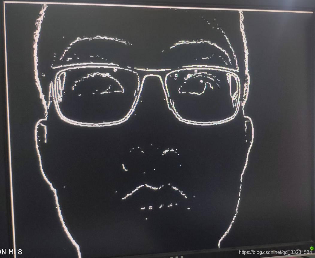
六、上板验证
无阈值灰度边缘检测

阈值为130的边缘检测

阈值为100的边缘检测

阈值为80的边缘检测
阈值为50的边缘检测


 3万+
3万+


 被折叠的 条评论
为什么被折叠?
被折叠的 条评论
为什么被折叠?
 到【灌水乐园】发言


