


 文章介绍了基于DFIG的风电系统中网侧变换器的控制策略,采用的控制方法类似三相整流器。仿真模型包括变压器、网侧变换器和控制器,其中变压器电压比设定为1:3,对应定子转子匝数比。转子侧变换器控制已折算到定子侧,并添加了电网电压前馈。仿真结果显示网侧变换器能有效控制电容电压和无功功率。此外,代码展示了系统的参数设置和PI控制器参数计算。
DFIG控制4:网侧变换器控制
本文的仿真模型基于
DFIM Tutorial 4 - Grid Converter Implementation in a Wind Turbine based on DFIG
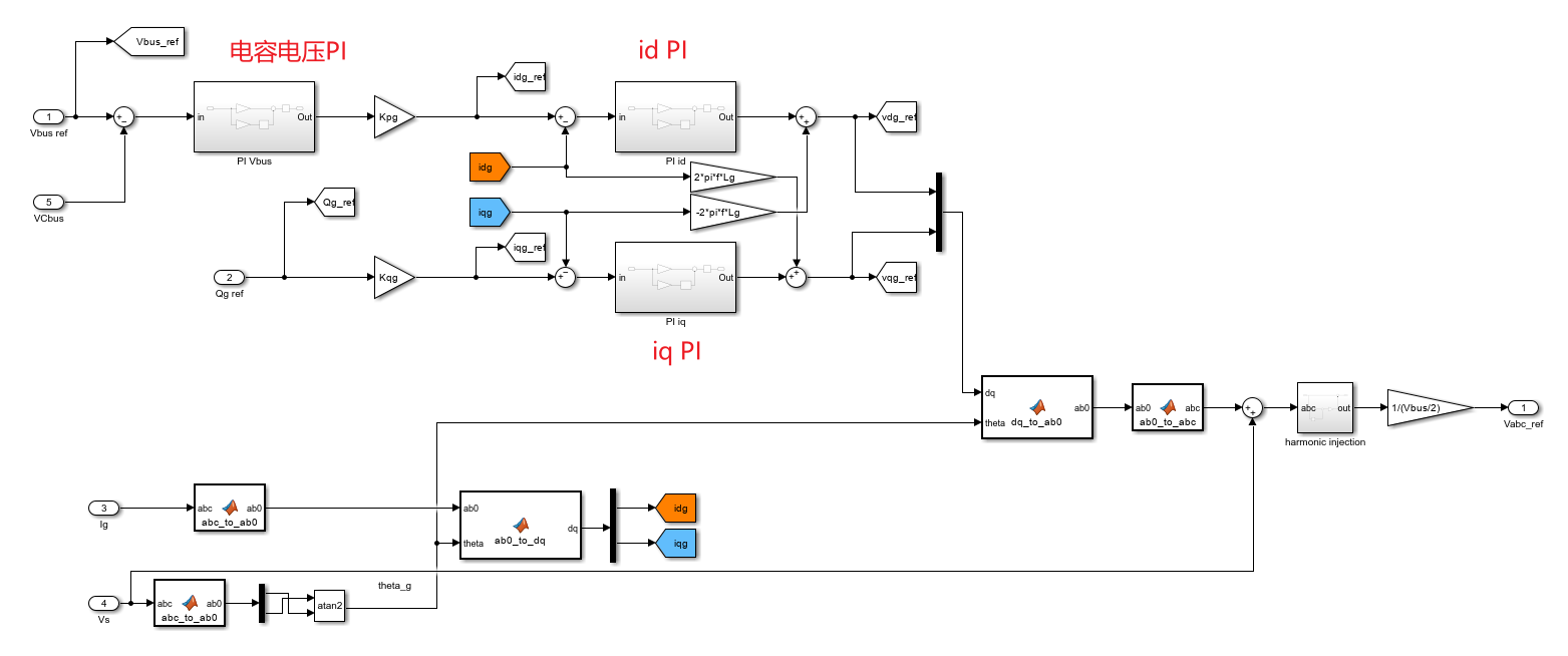
控制策略
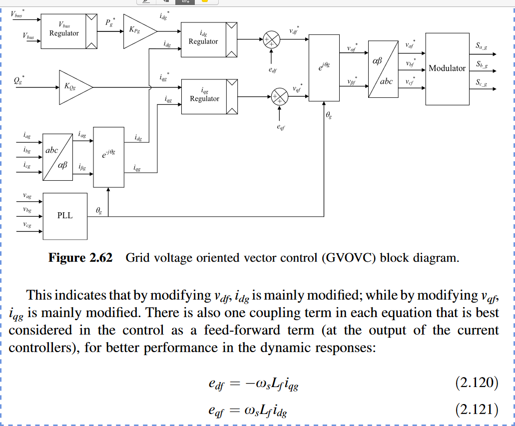
网侧的控制策略基于下图,看起来和三相整流器常用的控制策略相同。
G. Abad, J. Lopez, M. Rodriguez, L. Marroyo, and G. Iwanski, Doubly Fed Induction Machine: Modeling and Control for Wind Energy Generation. John Wiley & Sons, 2011.
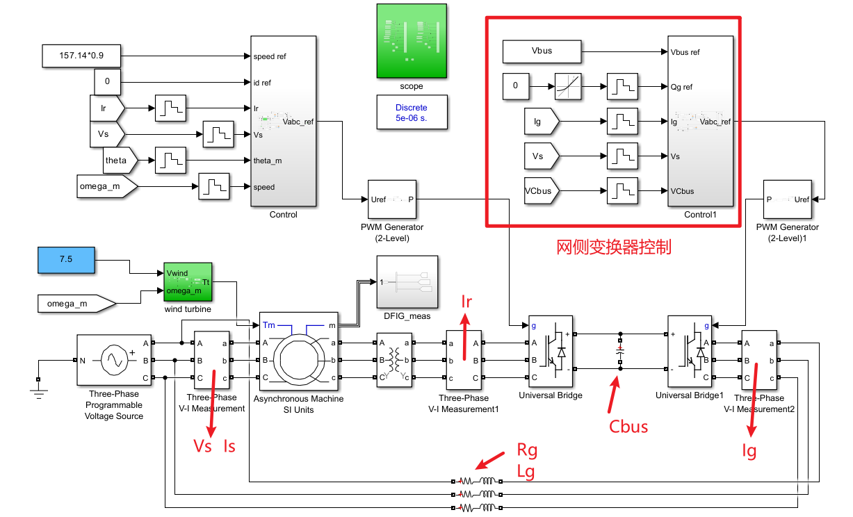
仿真模型
新增了网侧变换器和另外一些模块,如下:
变压器
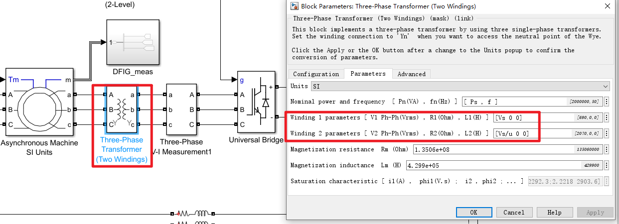
configuration: Y-Y
Core type: 默认
不是太理解教程里面变压器的电压之比:看起来是电压比是A:a=1:3?(u=1/3)。这是否符合教程里说的匝数比定子:转子=1:3?
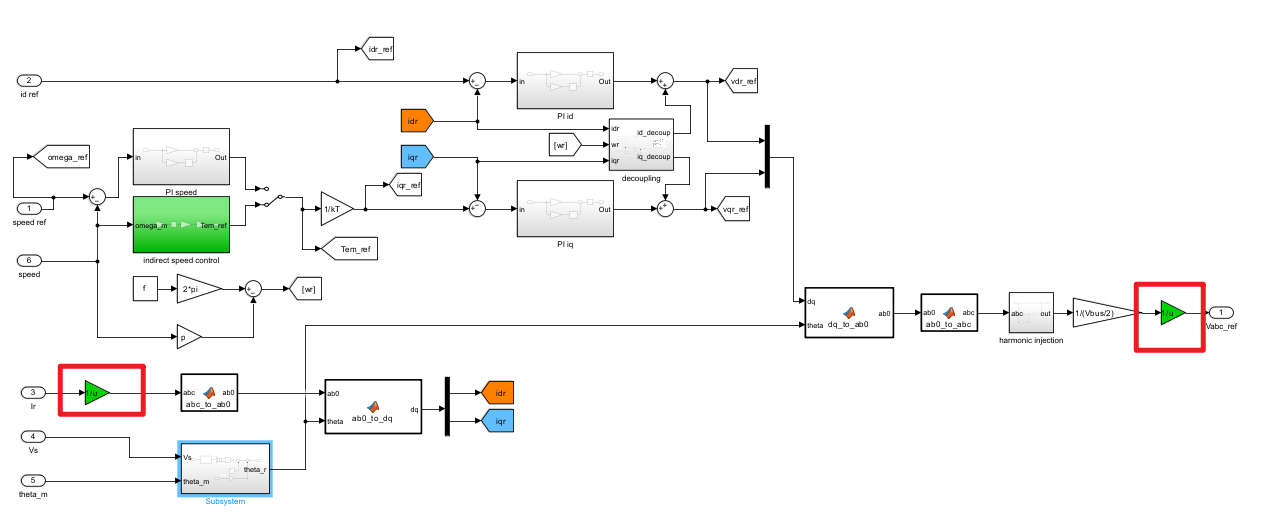
转子侧变换器控制模块修改
RSC的控制部分是全部折算到定子侧(referred to stator),所以计算时需要添加1/u的系数。如下。其他无变化。——具体还需要进一步理解。
控制器
完全按照上文的框图搭建。由转子侧变换器的控制模块修改而来,改动不大。
添加了一个电网电压前馈环节,直接加在控制器输出上,也是常用的设置。
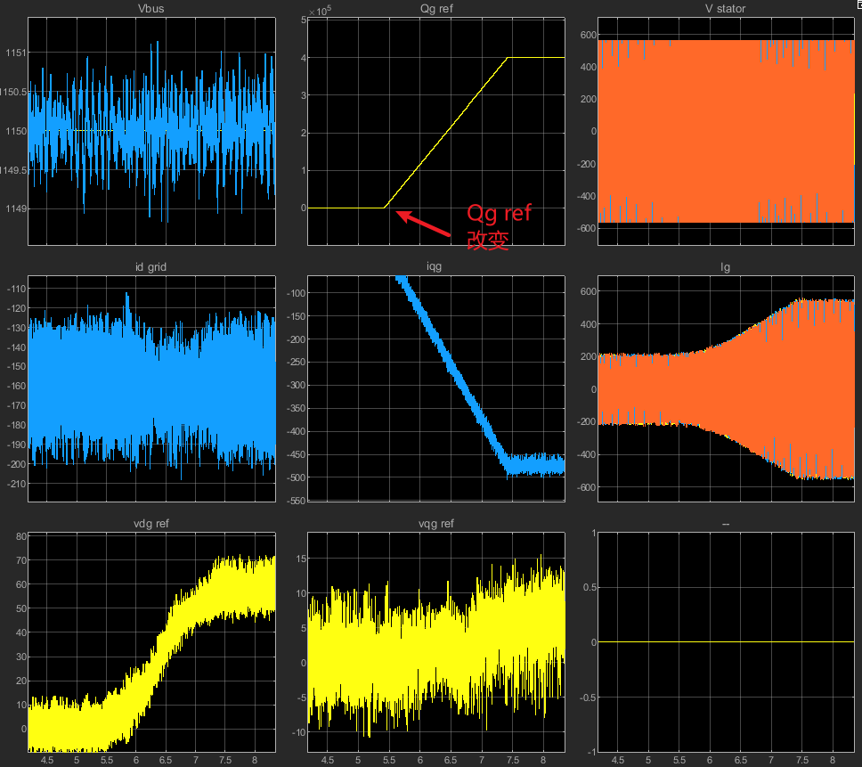
仿真结果
网侧变换器把电容电压控制在了设定值,无功也能正常调节。(没做软启动,还是有很大的冲击)。
初始化代码
- 注意:这里的
Vbus参数有变化。 - 添加了网侧的PI参数
clear

% DFIG parameters -> Rotor parameters referred to the stator side
f = 50; % Stator frequency (Hz)
Ps = 2e6; % Rated stator power (W)
n = 1500; % Rated rotational speed (rev/min)
Vs = 690; % Rated stator voltage (V)
Is = 1760; % Rated stator current (A)
Tem = 12732; % Rated torque (N.m)

p=2; % Pole pair

u = 1/3; % Stator/rotor turns ratio
Vr = 2070;    % Rated rotor voltage (non-reached) (V)
smax = 1/3;   % Maximum slip
Vr_stator = (Vr*smax) *u;    % Rated rotor voltage referred to stator (V)
Rs = 2.6e-3;    % Stator resistance(ohm)
Lsi = 0.087e-3; %  Leakage inductance (stator & rotor) (H)
Lm = 2.5e-3; %  Magnetizing inductance (H)
Rr = 2.9e-3; % Rotor resistance referred to stator (ohm)
Ls = Lm + Lsi; % Stator inductance (H)
Lr = Lm + Lsi; % Rotor inductance (H)
% Vbus = Vr_stator*sqrt(2); % DC de bus voltge referred to stator (V)
Vbus = 1150; % as in tutorial 4

sigma = 1-Lm^2/(Ls*Lr);

Fs = Vs*sqrt(2/3)/(2*pi*f);  % Stator Flux (aprox.) (Wb)
J = 127/2; % Inertia, originally 127, reduced by 2 to make the response faster
D = 1e-3; %damping

fsw = 4e3;
Ts =  1/fsw/50;

kT = -1.5*p*(Lm/Ls)*Fs; % kT, coef of output of the speed controller

tau_i = (sigma*Lr)/Rr;
tau_n = 0.05;
wni = 100*(1/tau_i);
wnn = 1/tau_n;

kp_id = (2*wni*sigma*Lr)-Rr;
kp_iq = kp_id;

ki_id = (wni^2)*Lr*sigma;
ki_iq = ki_id;

kp_n = (2*wnn*J)/p; %kp_n = (2*wnn*J)/p;
ki_n = (wnn^2)*J/p; %ki_n = (wnn^2)*J/p;


% Three blade wind turbine mode
N = 100; % Gearbox ratio
Radio= 42; % blade radius
ro= 1.225; % Air density

% Cp and Ct curves
beta=0;  % Pitch angle
ind2=1;

for lambda=0.1:0.01:11.8
    lambdai(ind2)= (1./((1./(lambda-0.02.*beta) + (0.003./ (beta^3+1)))));
    Cp(ind2)=0.73*(151./lambdai(ind2) - 0.58*beta - 0.002.*beta^2.14-13.2).*(exp(-18.4./lambdai (ind2)));
    Ct(ind2)=Cp(ind2)/lambda;
    ind2=ind2+1;
end

tab_lambda=[0.1:0.01:11.8];


% Kopt for MPPT
Cp_max = 0.44;
lambda_opt = 7.2;
Kopt = ((0.5*ro*pi* (Radio^5) *Cp_max)/(lambda_opt^3));
% Power curve in fucntion of wind speed

P = 1.0e+06 *[0,0,0,0,0,0,0,0.0472,0.1097,0.1815,0.2568,0.3418, ...
            0.4437,0.5642, 0.7046, 0.8667,1.0518,1.2616, 1.4976, 1.7613,2.0534,...
            2.3513,2.4024,2.4024,2.4024, 2.4024,2.4024,2.4024];
V = [0.0000,0.5556,1.1111,1.6667,2.2222,2.7778,3.3333,3.8889, 4.4444,...
    5.0000,5.5556,6.1111,6.6667,7.2222,7.7778,8.3333,8.8889,9.4444, ...
    10.0000,10.5556,11.1111, 11.6667,12.2222,12.7778,13.3333, 13.8889,...
    14.4444,15.0000];
% figure
% subplot(1,2,1)
% plot(tab_lambda, Ct, 'linewidth',1.5)
% xlabel('\lambda', 'fontsize',14)
% ylabel('Ct', 'fontsize',14)
% subplot(1,2,2)
% plot (V, P, 'linewidth', 1.5)
% grid
% xlabel('Wind speed (m/s)', 'fontsize',14)
% ylabel('Power (W)', 'fontsize',14)


% Grid side converter
Cbus = 80e-3; % DC bus capacitance
Rg = 20e-6; % Grid side filter's resisatance
Lg = 400e-6; % Grid side filter's inductance
Kpg = 1/(1.5*Vs*sqrt(2/3));
Kqg = -Kpg;

% PI regulators
tau_ig = Lg/Rg;
wnig = 60*2*pi;

kp_idg = (2*wnig*Lg)-Rg;
kp_iqg = kp_idg;
ki_idg = (wnig^2)*Lg;
ki_iqg = ki_idg;

kp_v = -1000;
ki_v = -300000;
一些问题
- 定子和转子电压电流等的折算。——还是得看模型。
- 变压器设置的问题,怎么表示匝数比定子:转子=1:3?


 783
783

 被折叠的 条评论
为什么被折叠?
被折叠的 条评论
为什么被折叠?
 到【灌水乐园】发言


