


前言
很早一段时间就想把红外解码的思路及代码写到博客上面,但是因为拖延症拖延到现在。
作者是使用的野火的指南针开发板(野火打钱),遥控器也使用的是野火店里面卖的。此处应该收广告费
本文仅介绍解码原理 ,因为发射很简单,就控制一个IO拉高拉低就行了,或者使用pwm等等。当然了如果解码你都会写了,发射那肯定是手到擒来。
1 解码原理
解码原理其实很简单,就是检测一个IO的高低电平持续时间就行了。当然了,红外的时序是有要求的,比如说起始信号、结束信号、数据码、持续信号等。这里的数据码包括系统识别码和操作码。
这里直接贴上野火的讲解
/*
遥控码由三部分组成
1、leader code 9ms的高电平 + 4.5ms 的低电平
2、系统识别码 区别不同的红外遥控设备
3、操作码 8bit操作码和8bit的操作反码组成
0和1均以0.56ms的低电平开始(实际测量是500us的样子),不同的是后面出现的高电平,
如果高电平是0.56ms(实际测量是500us的样子),则表示0,如果高电平是1.68ms(0.56*3=1.68)则表示1
结束码
高电平超过40ms,然后出现9ms的低电平
连发码 2.1ms的高电平
*/
2 思路讲解
本文这里原理讲解比较简单,看不懂的可以自行百度。这不是本文讲解的重点。
作者使用的是定时器加外部中断的方式进行解码。当然还有还有 别的方式可以进行解码,这个都无所谓。
首先的思路是计算IO的高低电平时间,那么定时器当然就少不了了 。
2.1 定时器配置
从解码原理那里可以看到高电平的持续时间范围为0.56ms到大于40ms。
那么我们开始配置定时器了,作者使用的stm32f103频率位72MHz,使用的定时器TIM3(当然你也可以选一个你自己喜欢的定时器)。那么我们配置定时器记一个数的时间位0.01ms,0.01ms对应的是100kHz,定时器的分频系数 = 72M/100K = 720。这个时候我们定时器计数只要超过40ms/0.01ms = 4000即可,这里作者设置为5000。当然了,定时器中断就不需要开了,因为我们用到的仅仅是计时而已。代码如下:
TIM_TimeBaseInitTypeDef  TIM_TimeBaseStructure;

RCC_APB1PeriphClockCmd(RCC_APB1Periph_TIM3, ENABLE);

TIM_TimeBaseStructure.TIM_Period = (5000-1);
TIM_TimeBaseStructure.TIM_Prescaler = (720-1);//0.01ms   50ms
TIM_TimeBaseStructure.TIM_ClockDivision = 0;
TIM_TimeBaseStructure.TIM_CounterMode = TIM_CounterMode_Up;
TIM_TimeBaseStructure.TIM_RepetitionCounter = 0;
TIM_TimeBaseInit(TIM3, &TIM_TimeBaseStructure);

TIM_Cmd(TIM3, ENABLE);
2.2 IO配置
IO的话,我们需要用到中断、输入模式。野火红外接收原理图如下
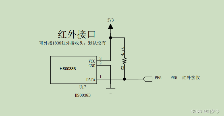
这里使用的IO是PE5,当然了使用哪个IO口都可以,仅仅是和你自己的板子配合起来使用而已。
这里我们配置IO模式为浮空上拉模式,中断触发模式配置为双边沿触发模式。
因为IO配置位输入模式了,速率是不需要的,所以那一行代码可有可无。
代码如下:
GPIO_InitTypeDef         GPIO_InitStructure;
NVIC_InitTypeDef         NVIC_InitStructure;
EXTI_InitTypeDef         EXTI_InitStructure;

RCC_APB2PeriphClockCmd(RCC_APB2Periph_GPIOE|RCC_APB2Periph_AFIO, ENABLE);

NVIC_PriorityGroupConfig(NVIC_PriorityGroup_4);

NVIC_InitStructure.NVIC_IRQChannel = EXTI9_5_IRQn;
NVIC_InitStructure.NVIC_IRQChannelPreemptionPriority = 1;
NVIC_InitStructure.NVIC_IRQChannelSubPriority = 0;
NVIC_InitStructure.NVIC_IRQChannelCmd = ENABLE;
NVIC_Init(&NVIC_InitStructure);

GPIO_InitStructure.GPIO_Pin = GPIO_Pin_5;
GPIO_InitStructure.GPIO_Mode = GPIO_Mode_IN_FLOATING;
GPIO_InitStructure.GPIO_Speed = GPIO_Speed_50MHz;
GPIO_Init(GPIOE, &GPIO_InitStructure);

GPIO_EXTILineConfig(GPIO_PortSourceGPIOE, GPIO_PinSource5);
EXTI_InitStructure.EXTI_Line = EXTI_Line5;
EXTI_InitStructure.EXTI_Mode = EXTI_Mode_Interrupt;
EXTI_InitStructure.EXTI_Trigger = EXTI_Trigger_Rising_Falling;
EXTI_InitStructure.EXTI_LineCmd = ENABLE;
EXTI_Init(&EXTI_InitStructure);
2.3 按键中断解码
对IO、TIM的配置可以看到很简单,这里开始讲解中断服务函数里面的内容了。
从最开始的内容我们可以知道红外解码最主要的数据有四个–系统识别码(8bit)+系统识别码反码(8bit)+操作码(8bit)+操作码反码(8bit)。这里我们直接用一个32bit的数据进行存储红外接收到的数据,而且通过分析红外的原理我们可以发现仅仅计算高电平的时间我们就可以完成解码的操作,当然了作者这里是进行了偷懒操作,不提倡大家学习。
高电平时间计算方式位在io上升沿时清零定时器的计数值,在下降沿时记录定时器计数值即可。
再看下面代码时,可以先不看InfraredData结构体的代码内容以及#if、#endif的内容。
void EXTI9_5_IRQHandler(void)
{
	static uint32_t  irdata = 0;
#if   !Continuous
	static _Bool start = False;
#endif
	if(EXTI_GetITStatus(EXTI_Line5))
	{
		EXTI_ClearITPendingBit(EXTI_Line5);
		if(GPIO_ReadInputDataBit(GPIOE,GPIO_Pin_5))
		{
			/* 上升沿 */
			TIM_SetCounter(TIM3,0);
			InfraredHightime = 0;
		}
		else
		{
			/* 下降沿 */
			InfraredHightime = TIM_GetCounter(TIM3);
			if(InfraredHightime>400 && InfraredHightime<500)
			{
#if   !Continuous
				start = True;
#endif
				irdata = 0;
			}
#if   !Continuous
			else if(start)
			{
				if(0)
				{}
#endif
				else if(InfraredHightime>40 && InfraredHightime<72)
				{
					irdata <<= 1;
					irdata |= 0;
				}
				else if(InfraredHightime>150 && InfraredHightime<186)
				{
					irdata <<= 1;
					irdata |= 1;
				}
				else if((InfraredHightime>4000) || (InfraredHightime<220))
				{
#if   !Continuous
					start = False;
#endif
						InfraredData.sid = irdata>>24;
						InfraredData.nsid = irdata>>16;
						InfraredData.opcode = irdata>>8;
						InfraredData.nopcode = irdata>>0;
						InfraredData.ismark = True;
				}
#if   !Continuous
			}
#endif
		}
	}
}
可以看到作者是在下降沿的中断里才开始处理,代码具体内容就不进行讲解了,读者自行观看即可。
InfraredData结构体内容如下
ismark代表的是解码完成,也就是当前结构体的数据有效。
宏Continuous控制的是支持连续解码还是必须松开才能进行下次解码。
typedef struct
{
	uint8_t sid;//System identification code
	uint8_t nsid;//System identification code inverse code
	uint8_t opcode;//operation code
	uint8_t nopcode;//operation code inverse code
	_Bool ismark;//Infrared switching mark
}infrared_t;
完整代码如下
infrared.c
#include "infrared.h"

infrared_t InfraredData;
static uint16_t InfraredHightime = 0;

static void InfraredDataInit(void)
{
	InfraredData.ismark = False;
	InfraredData.opcode = 0;
	InfraredData.nopcode = 0;
	InfraredData.sid = 0;
	InfraredData.nsid = 0;
}
void InfraredInit(void)
{
	GPIO_InitTypeDef         GPIO_InitStructure;
	NVIC_InitTypeDef         NVIC_InitStructure;
	EXTI_InitTypeDef         EXTI_InitStructure;
	TIM_TimeBaseInitTypeDef  TIM_TimeBaseStructure;

	RCC_APB2PeriphClockCmd(RCC_APB2Periph_GPIOE|RCC_APB2Periph_AFIO, ENABLE);
	RCC_APB1PeriphClockCmd(RCC_APB1Periph_TIM3, ENABLE);
//	RCC_APB2PeriphClockCmd(RCC_APB2Periph_GPIOB,ENABLE);

	NVIC_InitStructure.NVIC_IRQChannel = EXTI9_5_IRQn;
	NVIC_InitStructure.NVIC_IRQChannelPreemptionPriority = 1;
	NVIC_InitStructure.NVIC_IRQChannelSubPriority = 0;
	NVIC_InitStructure.NVIC_IRQChannelCmd = ENABLE;
	NVIC_Init(&NVIC_InitStructure);

//	GPIO_InitStructure.GPIO_Pin = GPIO_Pin_0;
//	GPIO_InitStructure.GPIO_Mode = GPIO_Mode_Out_PP;
//	GPIO_InitStructure.GPIO_Speed = GPIO_Speed_50MHz;
//	GPIO_Init(GPIOB, &GPIO_InitStructure);

	GPIO_InitStructure.GPIO_Pin = GPIO_Pin_5;
	GPIO_InitStructure.GPIO_Mode = GPIO_Mode_IN_FLOATING;
	GPIO_InitStructure.GPIO_Speed = GPIO_Speed_50MHz;
	GPIO_Init(GPIOE, &GPIO_InitStructure);

	GPIO_EXTILineConfig(GPIO_PortSourceGPIOE, GPIO_PinSource5);
	EXTI_InitStructure.EXTI_Line = EXTI_Line5;
	EXTI_InitStructure.EXTI_Mode = EXTI_Mode_Interrupt;
	EXTI_InitStructure.EXTI_Trigger = EXTI_Trigger_Rising_Falling;
	EXTI_InitStructure.EXTI_LineCmd = ENABLE;
	EXTI_Init(&EXTI_InitStructure);

	TIM_TimeBaseStructure.TIM_Period = (5000-1);
	TIM_TimeBaseStructure.TIM_Prescaler = (720-1);//0.01ms   50ms
	TIM_TimeBaseStructure.TIM_ClockDivision = 0;
	TIM_TimeBaseStructure.TIM_CounterMode = TIM_CounterMode_Up;
	TIM_TimeBaseStructure.TIM_RepetitionCounter = 0;
	TIM_TimeBaseInit(TIM3, &TIM_TimeBaseStructure);

	TIM_Cmd(TIM3, ENABLE);
	InfraredDataInit();
}

void EXTI9_5_IRQHandler(void)
{
	static uint32_t  irdata = 0;
#if   !Continuous
	static _Bool start = False;
#endif
	if(EXTI_GetITStatus(EXTI_Line5))
	{
		EXTI_ClearITPendingBit(EXTI_Line5);
		if(GPIO_ReadInputDataBit(GPIOE,GPIO_Pin_5))
		{
			/* 上升沿 */
			TIM_SetCounter(TIM3,0);
			InfraredHightime = 0;
		}
		else
		{
			/* 下降沿 */
			InfraredHightime = TIM_GetCounter(TIM3);
			if(InfraredHightime>400 && InfraredHightime<500)
			{
#if   !Continuous
				start = True;
#endif
				irdata = 0;
			}
#if   !Continuous
			else if(start)
			{
				if(0)
				{}
#endif
				else if(InfraredHightime>40 && InfraredHightime<72)
				{
					irdata <<= 1;
					irdata |= 0;
				}
				else if(InfraredHightime>150 && InfraredHightime<186)
				{
					irdata <<= 1;
					irdata |= 1;
				}
				else if((InfraredHightime>4000) || (InfraredHightime<220))
				{
#if   !Continuous
					start = False;
#endif
						InfraredData.sid = irdata>>24;
						InfraredData.nsid = irdata>>16;
						InfraredData.opcode = irdata>>8;
						InfraredData.nopcode = irdata>>0;
						InfraredData.ismark = True;
				}
#if   !Continuous
			}
#endif
		}
	}
}
infrared.h
#ifndef   __INFRARED_H
#define   __INFRARED_H

#include "stm32f10x.h"

#define   False    0
#define   True     1

#define   Continuous    False

typedef struct
{
	uint8_t sid;//System identification code
	uint8_t nsid;//System identification code inverse code
	uint8_t opcode;//operation code
	uint8_t nopcode;//operation code inverse code
	_Bool ismark;//Infrared switching mark
}infrared_t;

extern infrared_t InfraredData;

void InfraredInit(void);

#endif
main.c
#include "stm32f10x.h"
#include "infrared.h"
#include "usart.h"

uint16_t Systime;
void EstimateOpcode(uint8_t opcode);
int main(void)
{
	//SysTick_Config(72000000 / 1000);
	NVIC_PriorityGroupConfig(NVIC_PriorityGroup_4);
	UsartInit(115200);
	InfraredInit();
	printf("红外测试程序\r\n");
  while (1)
  {
	  if(InfraredData.ismark)
		{
			InfraredData.ismark = False;
			EstimateOpcode(InfraredData.opcode);
			printf("读取的值%.2x\r\n",InfraredData.opcode);
		}
  }
}
void EstimateOpcode(uint8_t opcode)
{
	switch(InfraredData.opcode)
	{
		case 162:
			printf("电源\r\n");
			break;
		case 226:
			printf("menu\r\n");
			break;
		case 34:
			printf("test\r\n");
			break;
		case 2:
			printf("+\r\n");
			break;
		case 194:
			printf("return\r\n");
			break;
		case 224:
			printf("|<<\r\n");
			break;
		case 168:
			printf(">\r\n");
			break;
		case 144:
			printf(">>|\r\n");
			break;
		case 104:
			printf("0\r\n");
			break;
		case 152:
			printf("-\r\n");
			break;
		case 176:
			printf("c\r\n");
			break;
		case 48:
			printf("1\r\n");
			break;
		case 24:
			printf("2\r\n");
			break;
		case 122:
			printf("3\r\n");
			break;
		case 16:
			printf("4\r\n");
			break;
		case 56:
			printf("5\r\n");
			break;
		case 90:
			printf("6\r\n");
			break;
		case 66:
			printf("7\r\n");
			break;
		case 74:
			printf("8\r\n");
			break;
		case 82:
			printf("9\r\n");
			break;
		default:
			printf("unknown\r\n");
			break;
	}
}
结语
关于解码作者还想到一种通过定时器输入捕获的方式进行解码,等作者拖延症结束了编写完再发上来吧。
特别说明,使用的遥控器不同,操作码可能就不一样以及高电平持续时间可能会有误差,这个需要自己自行测试即可。


 6026
6026

 被折叠的 条评论
为什么被折叠?
被折叠的 条评论
为什么被折叠?
 到【灌水乐园】发言


