


1.协议要求
协议为帧传输,一共16字节。主要是2字节的固定帧头 EB 90,2字节的帧计数(用来计数发出的帧),10字节的数据和2字节的校验位

帧头:2字节,固定值 8’HEB、8’H90
帧计数:2字节,用来说明发出去帧是第几帧
数据:10字节,用于发送数据
校验位:2字节,和校验,将数据位累计后取反
2.架构设计
2.1整体架构设计
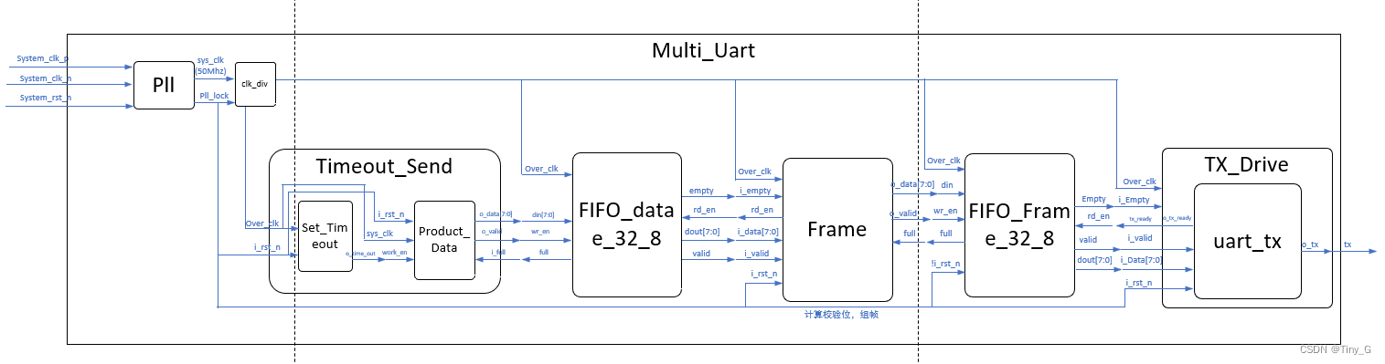
本架构基于黑金开发版Ax7101,开发工具vivado2022.3,整个协议的架构图设计如下:

整个架构的功能是实现帧的接收和帧的发送,该架构可以分成两个部分:解帧使用和组帧发送的两个部分。
数据流向解析:
-
组帧发送部分
晶振时钟(200Mhz)和板上复位信号先流入锁相环PLL,得到的是50Mhz的时钟(因为200Mzh时钟经PLL分频不能一次性分频到波特率时钟如9600,因此需要再次分频)。
50Mhz的时钟先流入分频模块clk_div将分频得到波特率率时钟的16倍时钟(如9600*16,这里之所以不用波特率时钟,是因为要在单字节接收模块uart_rx用过采样,为了节省资源所有的时钟都用这个波特时钟的16时钟,本文称之为over_clk)
经过分频后的over_clk 流入所有模块作为输入时钟,同时pll_lock信号作为复位信号sys_rst_n.(这里用plll_lock作为复位信号是因为,在pll_lock为低电平的时候,输出时钟是不稳定的,是有毛刺的。而当时pll_lock输入为高电平的时候才是输出的稳定时钟over_clk)
接着来到了主要功能实现模块,首先是用户会给你一个数据,让你把这个数据发出去,这里假设给你一帧数据(10字节),如果10字节每个字节是一样的,如都是8’H01。那么就是用uart_tx发送10次单字节模块就好了。然后,用户为了保证传输安全,他给你规定了一个协议(2byte帧头+2byte帧计数+10byte数据+2byte校验)。因此,你拿到数据,首先应该做的是先封装成一帧,然后再去想怎么将这一帧发出去的问题。
这就有了组帧模块Frame,通过Frame模块将用户输入的10字节数据封装成一帧,为了隔离组帧模块和单字节发送模块Tx_Drive,所以在这两个模块之间加了异步FIFO(FIFO_Frame),同时也是为了平衡组帧和发送这一帧的速率。因为组帧模块组帧完成后,输入的FIFO_Frame的是连续的16个字节,而发送模块是一字节一字节的发送的,两模块之间的速度存在差异。
而组帧模块Frame所做的就是将组帧好的16字节数据送入FIFO_Frame,然后继续组帧,继续送入…就这样一直工作。而Tx_Drive模块的功能是先从FIFO_Frame取出1字节,然后将1字节的数据通过串口tx发送出去。然后再到FIFO_Frame里面去取,再发…就这样就这实现了整个组帧发送部分。
-
解帧使用部分
首先输入端口是由tx发出的二进制数据流,所以先需要Rx_Drive模块将这个数据转换成16字节的8位数据,而在收到16字节之后,这16字节中只有10字节的数据,而用户需要只是这10字节的数据,而不是带帧格式的整个帧,所以需要解帧模块Unframe模块将16字节的模块中10字节数据提取出来。而中间的流动过程跟组帧模块相反,但思想几乎一模一样,唯一区别就是解帧模块Unframe要在Rx_Drive一字节一字节存入的FIFO_Unframe中一次性取出16字节,然后从这16字节中把数据取出来。
2.1.1组帧发送
主要构成:Frame(组帧模块)+FIFO_Frame(同步FIFO)+Tx_Drive(串口发送模块)
**主要功能:**将用户给的数据,先组帧,然后通过单字节串口将数据一字节一字节的方式发出去。
2.1.2解帧使用
主要构成:Unframe(解帧模块)+FIFO_Unframe(同步FIFO)+Rx_Drive(串口发送模块)
主要功能:将收到数据流解析成16字节,然后解帧模块再将其中的数据取出来,供用户使用。
2.2 定时发送架构设计
定时发送模块是属于上面整体架构的组帧发送部分,因为组帧发送需要出入10字节的数据,才能将数据组帧,然后发送出去,所以需要一个定时产生数据的模块。
3.模块代码分析
本章叙述流程,将会先从从定时发送发送多字节模块(即多了定时发送的组帧发送模块)展开叙述每个模块的具体细节和实现思路,然后将再将定时发送tx端产生的数据流,流入解帧接收部分,从而一点点随着数据的流动,逐渐由表及里,剖析代码。
3.1 定时模块 Timeout_Send
定时发送模块Timeout_Send为顶层模块,该模块是下面两个功能的封装:
(1)定时
(2)产生一帧要发送的数据(10字节)
参数控制:
- P_SYS_CLK :输入时钟,默认是9600*16
- P_SEND_BYTE_LENGTH:发送一帧长度,自动计算需要产生多少字节数据
- P_TIMEOUT_PRIOD:发送间隔,默认5ms发送一帧
框图:

参考代码:
`timescale 1ns / 1ps
// 定时发送模块,到时间后输出高电平

module Timeout_Send
#(
    parameter P_SYS_CLK             = 153_600   ,
    parameter P_SEND_BYTE_LENGTH    = 16       ,
    parameter P_TIMEOUT_PRIOD       = 500        //定时发送1帧数据,单位毫秒,默认5ms
)
(
    input           i_clk       ,             //时钟为50Mhz
    input           i_rst_n     ,             //工作使能信号
    input           i_full      ,

    output  [7:0]   o_data      ,             //输出的数据
    output          o_valid                   //输出数据的有效信号
);

wire                work_en;

Set_Timeout
#(
    .P_SYS_CLK      (P_SYS_CLK      )   ,
    .P_TIMEOUT_PRIOD(P_TIMEOUT_PRIOD)       //定时发送1帧数据,单位毫秒,默认50ms
)
Set_Timeout_U0
(
    .i_clk          (i_clk          )   ,   //时钟为50Mhz
    .i_rst_n        (i_rst_n        )   ,

    .o_timeout      (work_en        )       //时间到了就拉高一个周期
);

Product_Data
#(
    .P_SEND_BYTE_LENGTH (P_SEND_BYTE_LENGTH)
)
Product_Data_U0
(
    .i_clk          (i_clk          )   ,
    .i_rst_n        (i_rst_n        )   ,
    .i_work_en      (work_en        )   ,
    .i_full         (i_full         )   ,

    .o_data         (o_data         )   ,
    .o_valid        (o_valid        )
);
endmodule
3.1.1 定时模块Set_Timeout
主要功能:设置的定时时间到了,就拉高一个工作使能信号o_timeout,默认5ms拉高信号。
参数控制:
- P_SYS_CLK:输入时钟,默认分频时钟的16倍,每个周期是10^6/(9600*16)=6.51us
- P_TIMEOUT_PRIOD:发送间隔,定时发送1帧数据,单位毫秒,默认5ms
参考代码:
`timescale 1ns / 1ns
module Set_Timeout
#(
    parameter P_SYS_CLK         = 153_600,  //分频时钟的16倍,每个周期是10^6/(9600*16)=6.51us
    parameter P_TIMEOUT_PRIOD   = 500       //定时发送1帧数据,单位毫秒,默认5ms
)
(
    input   i_clk       ,                   //时钟为50Mhz
    input   i_rst_n     ,

    output  o_timeout                       //时间到了就拉高一个周期
);

/***************parameter*************/
localparam      P_CNT_MAX       = P_TIMEOUT_PRIOD*P_SYS_CLK/1000_000;

reg             ro_timeout              ;
reg     [31:0]  r_cnt                   ;

assign          o_timeout = ro_timeout  ;
/***************always****************/
always @(posedge i_clk, negedge i_rst_n) begin
    if(~i_rst_n)
        r_cnt <= 32'd0;
    else if(r_cnt == P_CNT_MAX - 1)
        r_cnt <= 32'd0;
    else
        r_cnt <= r_cnt + 1;
end

always @(posedge i_clk, negedge i_rst_n) begin
    if(~i_rst_n)
        ro_timeout <= 1'b0;
    else if(r_cnt == P_CNT_MAX - 1)
        ro_timeout <= ro_timeout + 1;
    else
        ro_timeout <= ro_timeout;
end
endmodule
3.1.2 数据产生模块Product_Data
主要功能:收到拉高的工作使能信号,就输出一帧数据,默认50ms输出一帧数据。
参数控制:
- P_SEND_BYTE_LENGTH:一帧要发送的字节的长度,自动除去帧头、帧计数和帧校验,发需要发的字节长度。列如16字节:16-2-2-2
参考代码:
`timescale 1ns / 1ps

//产生模拟数据模块:当时工作使能信号为高,同时有握手信号的才输出数据
module Product_Data
#(
    parameter P_SEND_BYTE_LENGTH = 16
)
(
    input           i_clk       ,
    input           i_rst_n     ,
    input           i_work_en   ,
    input           i_full      ,

    output  [7:0]   o_data      ,
    output          o_valid
);

/***************function**************/
/***************parameter*************/
localparam P_FRAME_DATA_LENGTH = P_SEND_BYTE_LENGTH -2-2-2;//一帧数据的长度
/***************port******************/
/***************mechine***************/
/***************reg*******************/
reg   [7:0]         ri_data     ;
reg                 ri_valid    ;
reg   [9:0]         valid_cnt   ;
reg                 send_en     ;
reg   [7:0]         r_byte_cnt  ;   //输出字节计数器,用来约束只发一帧数据
reg                 is_finish   ;   //完整输出一帧的后拉高信号,不在产生数据
/***************wire******************/
wire                wo_rd_en    ;
/***************component*************/
localparam          P_VALID_CNT = 10 ;
/***************assign****************/
assign              wo_rd_en = ~i_full  ;
assign              o_data   = ri_data  ;
assign              o_valid  = ri_valid ;
/***************always****************/
always @(posedge i_clk,negedge i_rst_n) begin   //限制发送一帧数据长度计数器
    if(~i_rst_n)
        r_byte_cnt <= 'd0;
    else if(r_byte_cnt == P_FRAME_DATA_LENGTH)
        r_byte_cnt <= 'd0;
    else if(ri_valid && ~is_finish)
        r_byte_cnt <= r_byte_cnt + 1;
    else
        r_byte_cnt <= r_byte_cnt;
end
always @(posedge i_clk ,negedge i_rst_n) begin
    if(~i_rst_n)
        is_finish <= 'd0;
    else if(~i_work_en)
        is_finish <= 'd0;
    else if(r_byte_cnt == P_FRAME_DATA_LENGTH)
        is_finish <= 'd1;
    else
        is_finish <= is_finish;
end
always@(posedge i_clk,negedge i_rst_n)begin //发送使能,当拉高的时候,处于发数据阶段
    if(~i_rst_n)
        send_en <= 'd0;
    else if(r_byte_cnt == P_FRAME_DATA_LENGTH && valid_cnt == P_VALID_CNT-1)
        send_en <= 'd0;
    else if(valid_cnt == P_VALID_CNT-1)
        send_en <= 'd0;
    else if(wo_rd_en && i_work_en && is_finish==0)
        send_en <= 'd1;
    else
        send_en <= send_en;
end
always @(posedge i_clk,negedge i_rst_n) begin
    if(~i_rst_n)
        valid_cnt <= 'd0;
    else if(valid_cnt == P_VALID_CNT)
        valid_cnt <= 'd0;
    else if(wo_rd_en  && i_work_en && ~is_finish)
        valid_cnt <= valid_cnt+1;
    else
        valid_cnt <= 'd0;
end
always @(posedge i_clk,negedge i_rst_n) begin
    if(~i_rst_n)
        ri_data <= 'd0;
    else if(~wo_rd_en)
        ri_data <= 'd0;
    else if(~send_en && i_work_en)
        ri_data <= ri_data + 1;
    else
        ri_data <= ri_data;
end
always @(posedge i_clk,negedge i_rst_n) begin
    if(~i_rst_n)
        ri_valid <= 'd0;
    else if(valid_cnt == P_VALID_CNT-1 && ~is_finish)
        ri_valid <= 1'b1;
    else
        ri_valid <= 'd0;
end
endmodule
3.2组帧发送
3.2.1组帧模块Frame
主要功能:将用户输入的数据封装成帧发送出去
参数控制:
- P_CRC_POLY:CRC校验的多项式,默认使用和校验,要用需要解开注释部分。默认CRC-16模型
- P_FIRST_MARK:帧头第一位,默认为8’HEB。
- P_SECOND_MARK:帧头第二位,默认为8’H90。
- P_SEND_BYTE_LENGTH:待发送的一帧长度,默认16字节。
框图:

参考代码:
`timescale 100ps / 1ps
/*计算机校验位,组帧发出去*/

module Frame
#(
    parameter       P_CRC_POLY          = 16'H8005  ,    //CRC校验中的多项式
    parameter       P_FIRST_MARK        = 8'HEB     ,
    parameter       P_SECOND_MARK       = 8'H90     ,
    parameter       P_SEND_BYTE_LENGTH  = 16

)
(
    input           i_clk       ,
    input           i_rst_n     ,
    input   [7:0]   i_data      ,
    input           i_valid     ,
    input           i_full      ,   //写入的FIFO是否满
    input           i_empty     ,   //被读入的FIFO是否空,当其拉高的时候读使能不在有效

    output  [7:0]   o_data      ,
    output          o_rd_en     ,             //读使能信号,当fifo非空且需要读数据的拉高
    output          o_valid
);
/***************function**************/
    function    automatic [15:0]  get_CRC;	//生成CRC校验的函数
    input   [15:0]      i_CRC_reg;
    input   [7:0]       i_f_poly;
    integer i;
    begin
        for(i = 0;i<8;i = i+1)begin
            i_CRC_reg = i_CRC_reg >> 1;
            if(i_CRC_reg[0] == 1)
                 i_CRC_reg = i_CRC_reg ^ {1'b1,i_f_poly};
        end
        get_CRC = i_CRC_reg;
    end
endfunction

    function automatic [15:0] get_Sum;	//累加函数,用于生成累加校验checksum
    input   [15:0]      i_sum_reg;
    input   [7:0]       i_sum_item;
    get_Sum  = i_sum_reg + i_sum_item;
endfunction

/***************parameter*************/
localparam          P_VALID_CNT = 3;
/***************port******************/
/***************mechine***************/
/***************reg*******************/
reg     [7:0]       ro_data             ;
reg                 ro_valid            ;
reg                 ro_valid_1d         ;
reg     [15:0]      r_CRC_Reg           ;       //原始数据左移之后的16位数据
reg     [4:0]       r_byte_cnt          ;       //接收字节计数器
reg     [79:0]      r_recive_container  ;
reg     [4:0]       r_send_byte_cnt     ;       //发送字节计数器
reg                 r_send_lock         ;       //接收的时候为低电平,高电平为发送状态
reg                 ro_rd_en            ;
reg     [1:0]       r_valid_cnt         ;
reg     [15:0]      r_frame_cnt         ;       //帧计数器
/***************wire******************/
/***************component*************/
/***************assign****************/
assign              o_data  = ro_data       ;
assign              o_valid = ro_valid_1d   ;
assign              o_rd_en = ro_rd_en      ;
/***************always****************/

always @(posedge i_clk,negedge i_rst_n) begin
    if(~i_rst_n)
        r_byte_cnt <= 'd0;
    else if(r_byte_cnt == (P_SEND_BYTE_LENGTH - 4-2))      //去除帧头标志位和校验位
        r_byte_cnt <= 'd0;
    else if(i_valid)
        r_byte_cnt <= r_byte_cnt + 1;
    else
        r_byte_cnt <= r_byte_cnt;
end

always @(posedge i_clk,negedge i_rst_n) begin           //1代表空闲
    if(~i_rst_n)
        ro_rd_en <= 'd1;
    else if(r_byte_cnt == (P_SEND_BYTE_LENGTH - 4-2))     //提前1位拉高,11位的时候拉高,然后valid慢数据1位,所以要提前两位
        ro_rd_en <= 'd0;
    else if(r_send_byte_cnt == P_SEND_BYTE_LENGTH && r_valid_cnt == 0 && ~i_empty)
        ro_rd_en <= 'd1;
    else if(r_byte_cnt <(P_SEND_BYTE_LENGTH - 4-2)&&r_send_byte_cnt == 0 && ~i_empty)
        ro_rd_en <= 'd1;
    else
        ro_rd_en <= ro_rd_en;
end

always @(posedge i_clk,negedge i_rst_n) begin           //接收的时候为低电平,高电平为发送状态
    if(~i_rst_n)
        r_send_lock <= 1'b0;
    else if(r_byte_cnt == (P_SEND_BYTE_LENGTH - 4-2) && ~i_full)     //当接受完12为数据,就开始准备发送
        r_send_lock <= 1'b1;
    else if(r_send_byte_cnt == P_SEND_BYTE_LENGTH && r_valid_cnt == 0)      //当发送完,变成接收状态
        r_send_lock <= 1'b0;
    else
        r_send_lock <= r_send_lock;
end

always @(posedge i_clk,negedge i_rst_n) begin
    if(~i_rst_n)
        // r_CRC_Reg <= 16'HFFFF;						//CRC校验的初始化
        r_CRC_Reg <= 'd0;
    else if(r_send_byte_cnt == P_SEND_BYTE_LENGTH  && r_valid_cnt == 0)
        // r_CRC_Reg <= 16'HFFFF;						//CRC校验的归零
        r_CRC_Reg <= 'd0;
   // else if(i_valid) begin                           	//CRC校验的写法:每收到一字节就先把包括这字节及其以前的所有字节全都计算出来,收完就计算完;
   		//r_CRC_Reg <= i_data^r_CRC_Reg[7:0];
    	//r_CRC_Reg <= get_CRC(r_CRC_Reg,P_CRC_POLY);
   // end
    else if(i_valid) begin                              //checksum校验的写法:先把12收完再计算出校验位
        r_CRC_Reg <= get_Sum(r_CRC_Reg,i_data);
    end
    else if(r_byte_cnt == (P_SEND_BYTE_LENGTH - 4-2))   //加上帧计数一起算
        r_CRC_Reg <= ~r_CRC_Reg;
    else
        r_CRC_Reg <= r_CRC_Reg;
end

always @(posedge i_clk, negedge i_rst_n) begin
    if(~i_rst_n)
        r_valid_cnt <= 'd0;
    else if(r_valid_cnt == P_VALID_CNT)
        r_valid_cnt <= 'd0;
    else if(r_send_lock)
        r_valid_cnt <= r_valid_cnt + 1;
    else
        r_valid_cnt <= 'd0;
end

always@(posedge i_clk, negedge i_rst_n)begin
    if(~i_rst_n)
        r_send_byte_cnt <= 'd0;
    else if(r_send_byte_cnt == P_SEND_BYTE_LENGTH && r_valid_cnt == 0)
        r_send_byte_cnt <= 'd0;
    else if(r_send_lock && r_valid_cnt == 0)
        r_send_byte_cnt <= r_send_byte_cnt+1;
    else
        r_send_byte_cnt <= r_send_byte_cnt;
end

always @(posedge i_clk, negedge i_rst_n) begin
    if(~i_rst_n)
        ro_valid <= 1'b0;
    else if(r_send_lock && r_send_byte_cnt <=P_SEND_BYTE_LENGTH && r_valid_cnt == P_VALID_CNT)
        ro_valid <= 1'b1;
    else
        ro_valid <= 1'b0;
end

always@(posedge i_clk,negedge i_rst_n)begin
    if(~i_rst_n)
        ro_valid_1d <= 1'b0;
    else
        ro_valid_1d <= ro_valid;
end

always @(posedge i_clk, negedge i_rst_n) begin
    if(~i_rst_n)
        r_recive_container <= 'd0;
    else if(r_send_byte_cnt == P_SEND_BYTE_LENGTH && r_valid_cnt == 0)
        r_recive_container <= 'd0;
    else if(i_valid)
        r_recive_container <= {i_data,r_recive_container[79:8]};
    else if(r_valid_cnt == 2 && r_send_byte_cnt > 4 && r_send_byte_cnt < P_SEND_BYTE_LENGTH-1)
        r_recive_container <= r_recive_container>>8;
    else
        r_recive_container <= r_recive_container;
end

always @(posedge i_clk, negedge i_rst_n) begin
    if(~i_rst_n)
        ro_data <= 'd0;
    else if(r_send_byte_cnt == 0 && r_valid_cnt == 1)
        ro_data <= 'd0;
    else if( r_send_lock && ~i_full && r_send_byte_cnt==1)
        ro_data <= 8'HEB;
    else if( r_send_lock && ~i_full && r_send_byte_cnt==2)
        ro_data <= 8'H90;
    else if( r_send_lock && ~i_full && r_send_byte_cnt==3)
        ro_data <= r_frame_cnt[7:0];
    else if( r_send_lock && ~i_full && r_send_byte_cnt==4)
        ro_data <= r_frame_cnt[15:8];
    else if( r_valid_cnt == 1 && r_send_byte_cnt > 4 && r_send_byte_cnt < P_SEND_BYTE_LENGTH-1) //接收完12字节数据,同时算出CRC校验码/累加和码
        ro_data <= r_recive_container[7:0];
    else if(r_valid_cnt == 1 && r_send_byte_cnt == P_SEND_BYTE_LENGTH - 1)
        ro_data <= r_CRC_Reg[7:0];
    else if(r_valid_cnt == 1 && r_send_byte_cnt== P_SEND_BYTE_LENGTH)
        ro_data <= r_CRC_Reg[15:8];
    else
        ro_data <= ro_data;
end

//帧计数器的赋值
always @(posedge i_clk, negedge i_rst_n) begin
    if(~i_rst_n)
        r_frame_cnt <= 'd0;
    else if(r_byte_cnt == (P_SEND_BYTE_LENGTH - 4-2)) //提前1时钟周期,让最后一个数据接收完的时候,把
        r_frame_cnt <= r_frame_cnt + 1;
    else
        r_frame_cnt <= r_frame_cnt;
end
endmodule
3.2.2 单字节发送的顶层模块Tx_Drive
主要功能:用来控制底层模块uart_tx模块
参数控制:
- P_SYS_CLOCK:输入时钟,默认50Mhz.
- P_UART_BAUDRATE:波特率,默认9600
- P_UART_STOP_WIDTH:停止位长度,默认为1
- P_UART_PARITY_WIDTH:1代表奇校验,2代表偶校验,0代表无校验,默认奇校验
- P_OVER_SAMPLE:过采样倍数,默认16倍
框图:

参考代码:
`timescale 1ns / 1ps

module Tx_Drive
#(
    parameter               P_SYS_CLOCK           =   50_000_000    ,   //系统时钟可配置,默认50MHZ
    parameter               P_UART_BAUDRATE       =   256000        ,   //波特率可配置,默认9600
    parameter               P_UART_STOP_WIDTH     =   1             ,   //停止位宽度,默认1位
    parameter               P_UART_PARITY_WIDTH   =   1             ,   //校验位,默认0,0不校验,1奇校验,2偶校验
    parameter               P_OVER_SAMPLE         =   16                //接收模块的过采样次数
)
(
    input                   i_sys_clk                               ,
    input                   i_rst_n                                 ,
    input                   i_valid                                 ,
    input   [7:0]           i_data                                  ,
    input                   i_empty                                 ,

    output                  o_tx                                    ,
    output                  o_tx_ready

);

localparam                  BAUD_CNT = P_SYS_CLOCK / P_UART_BAUDRATE;

wire                        wo_tx                   ;
wire                        w_uart_tx_ready         ;
reg                         w_tx_drive_ready        ;

assign                      o_tx_ready = w_uart_tx_ready && ~i_empty && w_tx_drive_ready;
assign                      o_tx = wo_tx;
wire                        o_tx_end;

uart_tx
#(
    .P_SYS_CLOCK            (P_SYS_CLOCK        )   ,   //系统时钟可配置,默认50MHZ
    .P_UART_BAUDRATE        (P_UART_BAUDRATE    )   ,   //波特率可配置,默认9600
    .P_UART_DATA_WIDTH      (8                  )   ,   //发送数据位可配置,默认8位
    .P_UART_STOP_WIDTH      (P_UART_STOP_WIDTH  )   ,   //停止位宽度,默认1位
    .P_UART_PARITY_WIDTH    (P_UART_PARITY_WIDTH)       //校验位宽度,0为无校验,1为奇校验,2位偶校验

)
uart_tx_u0
(
    .i_clk                  (i_sys_clk          )   ,
    .i_rst                  (i_rst_n            )   ,
    .i_user_tx_data         (i_data             )   ,   //用户待发送的数据
    .i_user_tx_data_valid   (i_valid            )   ,   //数据发送的有效信号

    .o_uart_tx              (wo_tx              )   ,
    .o_user_tx_ready        (w_uart_tx_ready    )   ,   //数据准备信号,当有效信号和准备信号同时为高的时候,发送的数据才是有效的
    .o_user_tx_end          (o_tx_end           )
);

reg                         o_tx_end_1d;
reg         [3:0]           work_cnt;
localparam                  P_CNT_MAX = 3;

always @(posedge i_sys_clk,negedge i_rst_n) begin
    if(~i_rst_n)
        o_tx_end_1d <= 'd0;
    else
        o_tx_end_1d <= o_tx_end;
end

always @(posedge i_sys_clk,negedge i_rst_n) begin
    if(~i_rst_n)
        work_cnt <= 'd0;
    else if(~w_tx_drive_ready&& ~i_empty&&work_cnt<P_CNT_MAX)
        work_cnt <= work_cnt + 1;
    else
        work_cnt <= work_cnt;
end

always @(posedge i_sys_clk,negedge i_rst_n) begin
    if(~i_rst_n)
        w_tx_drive_ready <= 'd0;
    else if(work_cnt == 2)
        w_tx_drive_ready <= 'd1;                   				//第一次触发
    else if(i_valid)
        w_tx_drive_ready <= 'd0;
    else if(o_tx_end && ~o_tx_end_1d )                           //只检测一次
        w_tx_drive_ready <= 'd1;
    else if(w_tx_drive_ready && ~o_tx_ready&&i_empty)
        w_tx_drive_ready <= 'd1;
    else if(~i_empty)
        w_tx_drive_ready <= 'd0;
    else
        w_tx_drive_ready <= w_tx_drive_ready;
end
endmodule
3.2.3 单字节发送模块uart_tx
主要功能:输入一个5/6/7/8位数据,将这个数据转换成一个串行数据发送出去。
参数控制:
- P_SYS_CLOCK:输入时钟,默认50Mhz。
- P_UART_BAUDRATE:波特率,默认9600。
- P_UART_DATA_WIDTH:输入数据宽度,默认发送8bit数据。
- P_UART_STOP_WIDTH:停止位宽度,默认为1.
- P_UART_PARITY_WIDTH:校验位,默认无校验0,1奇校验,2偶校验。
- P_OVER_SAMPLE:过采样倍数,默认16倍采样。
状态图:

状态图解释:当模块处于空闲的时候是P_IDLE状态,当输入端数据有限信号拉高的同时本模块空闲的时候(即o_tx_ready为1),此时开始进入发送数据的起始位状态P_START,即bit计数器1。当bit计数器大于1的同时小于等于P_UART_DATA_WIDTH的时候,处于发送数据状态P_DATA。当发送完数据之后,判断是否需要发送校验位,当P_UART_PARITY_WIDTH大于0的时候,就进入校验状态,发送校验位;如果P_UART_PARITY_WIDTH等于0,就直接进入停止状态。最后都经过1bit的时间同时本模块空闲的时候,进入空闲状态;如果经过1bit之后,发现本模块还是处于忙碌状态(即o_tx_ready0)就说要发下一个数据,直接进入起始状态。
参考代码:
`timescale 1ns / 1ns

module uart_tx
#(
    parameter                       P_SYS_CLOCK           =   50_000_000    ,   //系统时钟可配置,默认50MHZ
    parameter                       P_UART_BAUDRATE       =   9600          ,   //波特率可配置,默认9600
    parameter                       P_UART_DATA_WIDTH     =   8             ,   //发送数据位可配置,默认8位
    parameter                       P_UART_STOP_WIDTH     =   1             ,   //停止位宽度,默认1位
    parameter                       P_UART_PARITY_WIDTH   =   0             ,   //校验位宽度,0为无校验,1为奇校验,2位偶校验
    parameter                       P_OVER_SAMPLE         =   16                //接收模块的过采样次数

)
(
    input                           i_clk                                   ,   //输入的时钟是波特率的16倍时钟,所以发出数据要持续16个时钟周期
    input                           i_rst                                   ,
    output                          o_uart_tx                               ,

    input   [P_UART_DATA_WIDTH-1:0] i_user_tx_data                          ,   //用户待发送的数据+校验位+停止位
    input                           i_user_tx_data_valid                    ,   //数据发送有效信号
    output                          o_user_tx_ready                         ,   //数据准备信号,当有效信号和准备信号同时为高的时候,发送的数据才是有效的
    output                          o_user_tx_end
);


/****************************状态机写法*********************************************/
/***************function**************/
/***************parameter*************/
localparam                          P_IDLE    =   4'd0                      ,   //状态机的定义
                                    P_START   =   4'd1                      ,
                                    P_DATA    =   4'd2                      ,
                                    P_PARITY  =   4'd3                      ,
                                    P_STOP    =   4'd4                      ;
/***************port******************/
/***************mechine***************/
/***************reg*******************/
reg         [3:0]                   ct,nt                                   ;   //状态机的现态和次态
reg                                 ro_uart_tx                              ;
reg                                 ro_user_tx_ready                        ;
reg         [15:0]                  r_bit_cnt                               ;
reg         [7:0]                   r_clk_cnt                               ;   //计数到16为一个波特率的时钟周期
reg         [P_UART_DATA_WIDTH-1:0] r_tx_data                               ;   //移位寄存器
reg                                 r_parity                                ;
/***************wire******************/
wire                                w_tx_active                             ;
reg                                 o_tx_end                                ;
reg                                 o_tx_end_1d                             ;
/***************component*************/
/***************assign****************/
assign                              o_uart_tx       = ro_uart_tx            ;
assign                              o_user_tx_ready = ro_user_tx_ready      ;
assign                              w_tx_active     = i_user_tx_data_valid & ro_user_tx_ready;  //两个同是为高表示可以开始发送数据
assign                              o_user_tx_end   = o_tx_end_1d           ;
/***************always****************/
always @(posedge i_clk,negedge i_rst) begin     //当激活信号开始的时候,就开始产生技术使能,让时钟计数16个周期为一个波特时钟周期
    if(~i_rst)
        r_clk_cnt <= 'd0;
    else if(r_clk_cnt == P_OVER_SAMPLE-1)
        r_clk_cnt <= 'd0;
    else if(~ro_user_tx_ready)
        r_clk_cnt <= r_clk_cnt + 1;
    else
        r_clk_cnt <= 'd0;

end

/***************状态机****************/
always @(posedge i_clk, negedge i_rst) begin            //状态机第一段:同步时序描述状态转移
    if(!i_rst)
        ct = P_IDLE;
    else
        ct = nt;
end

always@(*) begin                                        //状态机第二段:组合逻辑判断状态转移条件,描述状态转移规律
    case (ct)
        P_IDLE: begin
            if(w_tx_active)
                nt = P_START;
            else
                nt = P_IDLE;
        end
        P_START: begin
            if(r_clk_cnt == P_OVER_SAMPLE-1)
                nt = P_DATA;
            else
                nt = P_START;
        end
        P_DATA: begin
            if(r_bit_cnt ==  P_UART_DATA_WIDTH && r_clk_cnt == P_OVER_SAMPLE-1 &&P_UART_PARITY_WIDTH > 0)
                nt = P_PARITY;
            else if(r_bit_cnt == P_UART_DATA_WIDTH && r_clk_cnt == P_OVER_SAMPLE-1 && P_UART_PARITY_WIDTH == 0)
                nt = P_STOP;
            else
                nt = P_DATA;
        end
        P_PARITY: begin
            if(r_bit_cnt >= (P_UART_DATA_WIDTH +1) && P_UART_PARITY_WIDTH>0 &&r_clk_cnt == P_OVER_SAMPLE-1)
                nt = P_STOP;
            else
                nt = P_PARITY;
        end
        P_STOP: begin
            if(r_bit_cnt == P_UART_DATA_WIDTH + 1 + P_UART_STOP_WIDTH && P_UART_PARITY_WIDTH>0 && r_clk_cnt == P_OVER_SAMPLE-1)
                nt = P_IDLE;
            else if(r_bit_cnt == P_UART_DATA_WIDTH + P_UART_STOP_WIDTH && !P_UART_PARITY_WIDTH && r_clk_cnt == P_OVER_SAMPLE-1)
                nt = P_IDLE;
            else
                nt = P_STOP;
        end
        default: nt = P_IDLE;
    endcase
end


always @(posedge i_clk, negedge i_rst) begin
    if(~i_rst)
        ro_user_tx_ready <= 'd1;
    else if(w_tx_active)
        ro_user_tx_ready <= 'd0;
    else if(r_bit_cnt == P_UART_DATA_WIDTH+P_UART_STOP_WIDTH && !P_UART_PARITY_WIDTH && r_clk_cnt == P_OVER_SAMPLE-1)              //发送完数据拉高,表示tx模块已经空闲了
        ro_user_tx_ready <= 'd1;
    else if(r_bit_cnt == P_UART_DATA_WIDTH+1+P_UART_STOP_WIDTH && P_UART_PARITY_WIDTH>0 && r_clk_cnt == P_OVER_SAMPLE-1)              //发送完数据拉高,表示tx模块已经空闲了
        ro_user_tx_ready <= 'd1;
    else
        ro_user_tx_ready <= ro_user_tx_ready;
end

always @(posedge i_clk, negedge i_rst) begin
    if(!i_rst)
        r_bit_cnt <= 'd0;
    else if(r_bit_cnt == P_UART_DATA_WIDTH+P_UART_STOP_WIDTH && P_UART_PARITY_WIDTH==0 && r_clk_cnt == P_OVER_SAMPLE-1)
        r_bit_cnt <= 'd0;
    else if(r_bit_cnt == P_UART_DATA_WIDTH+1+P_UART_STOP_WIDTH && P_UART_PARITY_WIDTH>0 && r_clk_cnt == P_OVER_SAMPLE-1)
        r_bit_cnt <= 'd0;
    else if(!ro_user_tx_ready&& r_clk_cnt == P_OVER_SAMPLE-1)
        r_bit_cnt <= r_bit_cnt + 1;
    else
        r_bit_cnt <= r_bit_cnt;
end

always @(posedge i_clk, negedge i_rst) begin
    if(!i_rst)
        r_tx_data <= 'd0;
    else if(w_tx_active)
        r_tx_data <= i_user_tx_data;
    else if(r_bit_cnt>0&&r_bit_cnt<=P_UART_DATA_WIDTH && r_clk_cnt == P_OVER_SAMPLE-2)
        r_tx_data <= r_tx_data >> 1;
    else
        r_tx_data <= r_tx_data;
end

always @(posedge  i_clk,negedge i_rst) begin
    if(~i_rst)
        r_parity <= 1'b0;
    else if(ct == P_STOP)
        r_parity <= 1'b0;
    else if(ct == P_DATA && r_clk_cnt == P_OVER_SAMPLE-1)
        r_parity <= r_parity ^ r_tx_data[0];
    else
        r_parity <= r_parity;
end

always @(posedge i_clk, negedge i_rst) begin            //状态机第三段:时序逻辑描述输出
    if(!i_rst)
        ro_uart_tx <= 1'b1;
    else case(ct)
        P_IDLE  :   ro_uart_tx <= 1'b1;
        P_START :   ro_uart_tx <= 1'b0;
        P_DATA  :   ro_uart_tx <= r_tx_data[0];
        P_PARITY:   ro_uart_tx <= P_UART_PARITY_WIDTH==1?~r_parity:r_parity;
        P_STOP  :   ro_uart_tx <= 1'b1;
        default :   ro_uart_tx <= 1'b1;
    endcase
end

always @(posedge i_clk, negedge i_rst) begin        //结束标志,为高的时候代表空闲
    if(!i_rst)
        o_tx_end <= 1'b1;
    else if(ct == P_START)
        o_tx_end <= 1'b0;
    else if(ct == P_STOP && r_clk_cnt == P_OVER_SAMPLE-2)
        o_tx_end <= 1'b1;
    else
        o_tx_end <= o_tx_end;
end
always @(posedge i_clk, negedge i_rst) begin
    if(!i_rst)
        o_tx_end_1d <= 1'b0;
    else
        o_tx_end_1d <= o_tx_end;
end
endmodule
3.3 解帧使用
2.3.1 单字节接收模块顶层Rx_Drive
主要功能:控制单字节接收模块。
参数控制:
- P_SYS_CLOCK:输入时钟,默认50Mhz。
- P_UART_BAUDRATE:波特率,默认9600。
- P_UART_STOP_WIDTH:停止位宽度,默认为1.
- P_UART_PARITY_WIDTH:校验位,默认无校验0,1奇校验,2偶校验。
- P_OVER_SAMPLE:过采样倍数,默认16倍采样。
参考代码:
`timescale 1ns / 1ns

module Rx_Drive#(
    parameter               P_SYS_CLOCK           =   50_000_000    ,   //系统时钟可配置,默认50MHZ
    parameter               P_UART_BAUDRATE       =   9600          ,   //波特率可配置,默认9600
    parameter               P_UART_STOP_WIDTH     =   1             ,   //停止位宽度,默认1位
    parameter               P_UART_PARITY_WIDTH   =   1             ,   //校验位,默认0,0不校验,1奇校验,2偶校验
    parameter               P_OVER_SAMPLE         =   16                //过采样的时钟的倍率
)
(
    input                   i_clk                                   ,   //输入时钟乃过采样时钟
    input                   i_rst_n                                 ,
    input                   i_full                                  ,   //判断待写入的FIFO是否已满
    input                   i_rx                                    ,

    output                  o_rx_valid                              ,
    output      [7:0]       o_rx_data
);


//接收数据模块
uart_rx
#(
    .P_SYS_CLOCK            (P_SYS_CLOCK        )    ,   //系统时钟可配置,默认50MHZ
    .P_UART_BAUDRATE        (P_UART_BAUDRATE    )    ,   //波特率可配置,默认9600
    .P_UART_STOP_WIDTH      (P_UART_STOP_WIDTH  )    ,   //停止位宽度,默认1位
    .P_UART_PARITY_WIDTH    (P_UART_PARITY_WIDTH)    ,   //校验位,默认0,
    .P_OVER_SAMPLE          (P_OVER_SAMPLE      )        //过采样的时钟的倍率
)
uart_rx_u0
(
    .i_over_clk             (i_clk              )    ,   //过采样时钟
    .i_rst_n                (i_rst_n            )    ,
    .i_rx                   (i_rx               )    ,   //判断待写入的FIFO是否已满
    /***********************/
    .sys_clk                (sys_clk            )   ,
    /***********************/
    .o_rx_valid             (o_rx_valid         )    ,
    .o_rx_data              (o_rx_data          )
);
endmodule
3.3.2 单字节接收模块uart_rx
主要功能:将输入的5/6/7/8并行数据,串行的发送出去
参数控制:
- P_SYS_CLOCK:输入时钟,默认50Mhz。
- P_UART_BAUDRATE:波特率,默认9600。
- P_UART_DATA_WIDTH:输入数据宽度,默认发送8bit数据。
- P_UART_STOP_WIDTH:停止位宽度,默认为1.
- P_UART_PARITY_WIDTH:校验位,默认无校验0,1奇校验,2偶校验。
- P_OVER_SAMPLE:过采样倍数,默认16倍采样。
状态图:

状态图解释:开始的时候处于空闲状态P_IDLE,当检测起始位,进入起始位状态P_START,这个状态持续到起始位结束,即bit==0。当bit>0且小于等于P_UART_DATA_WIDTH时候,进入接受数据状态P_DATA,接收完了。根据P_UART_PARITY_WIDTH是否大于0,判断是否进入校验状态P_PARITY。如果P_UART_PARITY_WIDTH大于0,就进入校验状态P_PARITY,然后经过1bit时间,就进入停止状态,即对应停止位P_STOP.否则就直接进入停止状态,然后经过P_UART_STOP_WIDTH个bit时间长度进入P_IDLE.之所以没有直接接入起始位,是因为在发送端设计的时候会一定有空闲状态产生,具体可以看发送端握手信号o_tx_ready。
参考代码:两种实现方式,计数器和状态机,都能用,用的时候只需要注释另一个。
`timescale 1ns / 1ps
/*本模块采用的全在中间采样,包括起始位的判断也是*/

module uart_rx
#(
    parameter               P_SYS_CLOCK             =   50_000_000  ,   //系统时钟可配置,默认50MHZ
    parameter               P_UART_BAUDRATE         =   9600        ,   //波特率可配置,默认9600
    parameter               P_UART_PARITY_WIDTH     =   1           ,   //校验位,默认0,
    parameter               P_UART_STOP_WIDTH       =   1           ,   //停止位宽度,默认1位
    parameter               P_OVER_SAMPLE           =   16              //过采样的时钟的倍率
)
(
    input                   i_over_clk                              ,   //过采样时钟
    input                   i_rst_n                                 ,
    input                   i_rx                                    ,   //判断待写入的FIFO是否已满
    output                  o_rx_valid                              ,
    output      [7:0]       o_rx_data
);

/****************************计数器写法*********************************************/
localparam                  P_OVER_CHECK_MAX = P_OVER_SAMPLE/2; //控制采样到什么位置停,范围在P_OVER_SAMPL/2-P_OVER_SAMPLE
/***************function**************/
/***************parameter*************/
/***************port******************/
/***************mechine***************/
/***************reg*******************/
reg         [2:0]               r_rx_reg        ;   //延迟打拍
reg                             ri_rx_1d        ;   //打拍
reg                             ri_rx_2d        ;   //打拍
reg                             r_over_en       ;
reg         [7:0]               r_over_cnt      ;   //过采样计数器
reg                             r_start_flag    ;   //检测是否是起始位的信号
reg                             r_bit_en        ;
reg         [7:0]               r_bit_cnt       ;
reg                             r_get_flag      ;   //数据的过采样点
reg         [7:0]               r_data_container;   //装数据的移位寄存器
reg                             r_check         ;   //生成奇偶校验

reg         [7:0]               ro_rx_data      ;
reg                             ro_rx_valid     ;

/***************wire******************/
/***************component*************/
/***************assign****************/
assign                          o_rx_valid = ro_rx_valid;
assign                          o_rx_data = ro_rx_data  ;
/***************always****************/
always @(posedge i_over_clk,negedge i_rst_n) begin  //打拍
    if(!i_rst_n) begin
        r_rx_reg <= 3'b111;
        ri_rx_1d <= 'd0;
        ri_rx_2d <= 'd0;
    end
    else begin
        r_rx_reg <= {r_rx_reg[1:0],i_rx};
        ri_rx_1d <= r_rx_reg[2];
        ri_rx_2d <= ri_rx_1d;
    end
end

always @(posedge i_over_clk,negedge i_rst_n) begin
    if(!i_rst_n)
        r_over_en <= 'd0;
    else if(r_bit_cnt == 8+1+P_UART_STOP_WIDTH && r_over_cnt == P_OVER_SAMPLE-1 && P_UART_PARITY_WIDTH>0)
        r_over_en <= 'd0;
    else if(r_bit_cnt == 8+P_UART_STOP_WIDTH && r_over_cnt == P_OVER_SAMPLE-1 && P_UART_PARITY_WIDTH==0)
        r_over_en <= 'd0;
    else if(r_bit_cnt == 0 && r_over_cnt == P_OVER_CHECK_MAX+1&& r_bit_en==0)   //异常归零
        r_over_en <= 'd0;
    else if(r_rx_reg[2]==0 && ri_rx_1d)
        r_over_en <= 'd1;
    else
        r_over_en <= r_over_en;
end

always @(posedge i_over_clk,negedge i_rst_n) begin
    if(!i_rst_n)
        r_over_cnt <= 'd0;
    else if(r_over_cnt == P_OVER_SAMPLE -1)
        r_over_cnt <= 'd0;
    else if(r_bit_cnt == 0 && r_over_cnt == P_OVER_CHECK_MAX+1&& r_bit_en==0)   //异常归零
        r_over_cnt <= 'd0;
    else if(r_over_en)
        r_over_cnt <= r_over_cnt + 1;
    else
        r_over_cnt <= r_over_cnt;
end


always @(posedge i_over_clk,negedge i_rst_n) begin
    if(!i_rst_n)
        r_start_flag <= 'd0;
    else if(r_bit_cnt==0 && r_over_cnt == 8'd7 && ri_rx_1d==0 && r_bit_en==0)
        r_start_flag <= 'd1;
    else
        r_start_flag <= 'd0;
end


always @(posedge i_over_clk,negedge i_rst_n) begin
    if(!i_rst_n)
        r_bit_en <= 'd0;
    else if(r_bit_cnt == 8+1+P_UART_STOP_WIDTH && r_over_cnt == P_OVER_SAMPLE-1 && P_UART_PARITY_WIDTH>0)
        r_bit_en <= 'd0;
    else if(r_bit_cnt == 8+P_UART_STOP_WIDTH && r_over_cnt == P_OVER_SAMPLE-1 && P_UART_PARITY_WIDTH==0)
        r_bit_en <= 'd0;
    else if(r_start_flag)
        r_bit_en <= 'd1;
    else
        r_bit_en <= r_bit_en;
end

always @(posedge i_over_clk,negedge i_rst_n) begin
    if(!i_rst_n)
        r_bit_cnt <= 'd0;
    else if(r_bit_cnt == 8+1+P_UART_STOP_WIDTH && P_UART_STOP_WIDTH>0 && r_over_cnt == P_OVER_SAMPLE-1)
        r_bit_cnt <= 'd0;
    else if(r_bit_cnt == 8+P_UART_STOP_WIDTH && P_UART_STOP_WIDTH==0 && r_over_cnt == P_OVER_SAMPLE-1)
        r_bit_cnt <= 'd0;
    else if(r_bit_en && r_over_cnt == P_OVER_SAMPLE-1)
        r_bit_cnt <= r_bit_cnt + 1;
    else
        r_bit_cnt <= r_bit_cnt;
end

always @(posedge i_over_clk,negedge i_rst_n) begin
    if(!i_rst_n)
        r_get_flag <= 'd0;
    else if(r_bit_cnt >8'd0 && r_bit_cnt <8'd9 && r_over_cnt == P_OVER_CHECK_MAX-1)
        r_get_flag <= 'd1;
    else
        r_get_flag <= 'd0;
end

always @(posedge i_over_clk,negedge i_rst_n) begin
    if(!i_rst_n)
        r_data_container <= 'd0;
    else if(r_bit_cnt == 8+1+P_UART_STOP_WIDTH && P_UART_STOP_WIDTH>0 && r_over_cnt == P_OVER_SAMPLE-1)
        r_data_container <= 'd0;
    else if(r_bit_cnt == 8+P_UART_STOP_WIDTH && P_UART_STOP_WIDTH==0 && r_over_cnt == P_OVER_SAMPLE-1)
        r_data_container <= 'd0;
    else if(r_get_flag)
        r_data_container <= {ri_rx_2d,r_data_container[7:1]};
    else
        r_data_container <= r_data_container;

end

always @(posedge i_over_clk,negedge i_rst_n) begin
    if(!i_rst_n)
        r_check <= 'd0;
     else if(r_bit_cnt == 8+1+P_UART_STOP_WIDTH && P_UART_STOP_WIDTH>0 && r_over_cnt == P_OVER_SAMPLE-1)
        r_check <= 'd0;
    else if(r_bit_cnt == 8+P_UART_STOP_WIDTH && P_UART_STOP_WIDTH==0 && r_over_cnt == P_OVER_SAMPLE-1)
        r_check <= 'd0;
    else if(r_get_flag)
        r_check <= ri_rx_2d^r_check;
    else if(r_bit_cnt == 8'd9 && P_UART_PARITY_WIDTH == 1&& r_over_cnt == 0)  //在数据位后面时候就生成校验值,偶校验直接是异或值
        r_check <= !r_check;
    else
        r_check <= r_check;
end

always @(posedge i_over_clk,negedge i_rst_n) begin
    if(!i_rst_n)
        ro_rx_data <= 'd0;
    else if(r_bit_cnt == 9)    //直接输出
        ro_rx_data <= r_data_container;
    else
        ro_rx_data <= ro_rx_data;

end

always @(posedge i_over_clk,negedge i_rst_n) begin
    if(!i_rst_n)
        ro_rx_valid <= 'd0;
    else if(r_bit_cnt == 8'd9 && P_UART_PARITY_WIDTH>0 && r_over_cnt == 1)
        ro_rx_valid <= r_check == ri_rx_2d?1:0;
    else if(r_bit_cnt == 8'd9 && P_UART_PARITY_WIDTH == 0 && r_over_cnt == 1)
        ro_rx_valid <= 'd1;
    else
        ro_rx_valid <= 'd0;
end

/****************************状态机写法*********************************************/
// /***************function**************/
// localparam                  P_OVER_CHECK_MAX = P_OVER_SAMPLE/2; //控制采样到什么位置停,范围在P_OVER_SAMPL/2-P_OVER_SAMPLE

// /***************parameter*************/
// localparam                  P_IDLE   = 4'd0 ,
//                             P_START  = 4'd1 ,
//                             P_DATA   = 4'd2 ,
//                             P_PARITY = 4'd3 ,
//                             P_STOP   = 4'd4 ,
//                             P_ERROR  = 4'd5 ;


// /***************port******************/
// /***************mechine***************/
// /***************reg*******************/
// reg                         ro_rx_valid     ;   //输出数据有效信号的寄存器
// reg         [7:0]           ro_rx_data      ;   //输出数据

// reg                         ri_rx_d1        ;   //消除亚稳态
// reg                         ri_rx_d2        ;
// reg                         ri_rx_d3        ;

// reg                         ri_rx_1d        ;   //将输入数据延迟一拍
// reg                         ri_rx_2d        ;   //将输入数据再延迟一拍
// reg                         r_cnt_en        ;   //开始计数的使能信号
// reg         [7:0]           r_over_cnt      ;   //超采样计数器
// reg                         r_start_flag    ;   //在第一个低电平的中点点,采样,从而判断起始位
// reg                         r_bit_en        ;   //当检测起始信号之后,就开始拉高bit计数器的使能
// reg         [7:0]           r_bit_cnt       ;   //bit计数器
// reg                         r_get_flag      ;   //采样数据的采样信号
// reg                         r_check         ;   //进行奇偶校验的
// reg         [7:0]           r_data_container;   //数据移位寄存器

// reg         [3:0]           ct,nt       ;   //保存状态的状态机

// /***************wire******************/
// /***************component*************/
// /***************assign****************/
// assign                      o_rx_valid = ro_rx_valid;
// assign                      o_rx_data  = ro_rx_data ;
// /***************always****************/
// always @(posedge i_over_clk,negedge i_rst_n) begin  //延迟信号
//     if(!i_rst_n) begin
//         ri_rx_1d <= 'd0;
//         ri_rx_2d <= 'd0;

//         ri_rx_d1 <= 'd0;
//         ri_rx_d2 <= 'd0;
//         ri_rx_d3 <= 'd0;
//     end
//     else begin
//         ri_rx_1d <= ri_rx_d3;
//         ri_rx_2d <= ri_rx_1d;

//         ri_rx_d1 <= i_rx;
//         ri_rx_d2 <= ri_rx_d1;
//         ri_rx_d3 <= ri_rx_d2;
//     end
// end

// always @(posedge i_over_clk,negedge i_rst_n) begin  //当检测到下降沿的时候开始计数的使能信号
//     if(!i_rst_n)
//         r_cnt_en <= 'd0;
//     else if(ct == P_STOP && r_over_cnt == P_OVER_SAMPLE-1)   //当停止状态的时候归零
//         r_cnt_en <= 'd0;
//     else if(ri_rx_1d && !ri_rx_d3)
//         r_cnt_en <= 'd1;
//     else
//         r_cnt_en <= r_cnt_en;

// end
// always @(posedge i_over_clk,negedge i_rst_n) begin  //超采样时钟
//     if(!i_rst_n)
//         r_over_cnt <= 'd0;
//     else if(r_over_cnt == P_OVER_SAMPLE-1)  //正常归零
//         r_over_cnt <= 'd0;
//     else if(ct == P_IDLE && r_over_cnt == P_OVER_CHECK_MAX +2 && !r_bit_cnt )   //异常归零,即开始计数后,在1bit的时间内发现这个低电平不是起始信号
//         r_over_cnt <= 'd0;
//     else if(r_cnt_en)
//         r_over_cnt <= r_over_cnt + 8'd1;
//     else
//         r_over_cnt <= r_over_cnt;
// end

// always @(posedge i_over_clk,negedge i_rst_n) begin  //检测是否是起始位的信号
//     if(!i_rst_n)
//         r_start_flag <= 'd0;
//     else if(ct == P_IDLE && r_over_cnt == P_OVER_CHECK_MAX-1 && ri_rx_1d == 0)   //在计数到中点(7)的时候,就进行检查是否是起始位
//         r_start_flag <= 'd1;
//     else
//         r_start_flag <= 'd0;
// end

// always @(posedge i_over_clk,negedge i_rst_n) begin  //开始比特计数器的使能信号
//     if(!i_rst_n)
//         r_bit_en <= 'd0;
//     else if(ct == P_STOP && r_over_cnt == P_OVER_SAMPLE-1)
//         r_bit_en <= 'd0;
//     else if(r_start_flag)
//         r_bit_en <= 'd1;
//     else
//         r_bit_en <= r_bit_en;
// end
// always @(posedge i_over_clk,negedge i_rst_n) begin  //比特计数器
//     if(!i_rst_n)
//         r_bit_cnt <= 'd0;
//     else if(ct == P_STOP && r_over_cnt == P_OVER_SAMPLE-1)  //无校验和校验正确的时,归零
//         r_bit_cnt <= 'd0;
//     else if(ct == P_ERROR && r_over_cnt == P_OVER_SAMPLE-1)  //校验错误时,也归零
//         r_bit_cnt <= 'd0;
//     else if(r_bit_en && r_over_cnt == P_OVER_SAMPLE-1)
//         r_bit_cnt <= r_bit_cnt + 8'd1;
//     else
//         r_bit_cnt <= r_bit_cnt;
// end

// always @(posedge i_over_clk,negedge i_rst_n) begin  //中间采样信号,应该在中点的前一时刻
//     if(!i_rst_n)
//         r_get_flag <= 'd0;
//     else if(ct == P_DATA && r_over_cnt == P_OVER_CHECK_MAX-2)
//         r_get_flag <= 'd1;
//     else
//         r_get_flag <= 'd0;
// end

// always @(posedge i_over_clk,negedge i_rst_n) begin  //累计异或,从而算出校验位,跟传输校验位相比
//     if(!i_rst_n)
//         r_check <= 'd0;
//     else if(ct == P_STOP || ct == P_ERROR)
//         r_check <= 'd0;
//     else if(r_get_flag)
//         r_check <= r_check^ri_rx_2d;
//     else
//         r_check <= r_check;
// end
// always @(posedge i_over_clk,negedge i_rst_n) begin  //采样8位数据
//     if(!i_rst_n)
//         r_data_container <= 'd0;
//     else if(ct == P_STOP && r_over_cnt == P_OVER_SAMPLE-1)
//         r_data_container <= 'd0;
//     else if(ct == P_DATA && r_get_flag)
//         r_data_container <= {ri_rx_2d,r_data_container[7:1]};
//     else
//         r_data_container <= r_data_container;
// end


// //状态机第一段:时序逻辑描述现态和次态转移
// always @(posedge i_over_clk,negedge i_rst_n) begin
//     if(!i_rst_n)
//         ct = P_IDLE;
//     else
//         ct = nt;
// end
// //状态机第二段:组合逻辑描述状态转移规律
// always@(*)begin
//     case (ct)
//         P_IDLE:begin
//             if(r_start_flag)
//                 nt = P_START;
//             else
//                 nt = P_IDLE;
//         end
//         P_START:begin
//             if(r_bit_cnt>0 && r_bit_cnt < 8'd9) //数据位八位
//                 nt = P_DATA;
//             else
//                 nt = P_START;
//         end
//         P_DATA:begin
//             if(r_bit_cnt > 8'd8 && P_UART_PARITY_WIDTH == 0)   //无校验位
//                 nt = P_STOP;
//             else if(r_bit_cnt > 8'd8 && P_UART_PARITY_WIDTH > 0)   //无校验位
//                 nt = P_PARITY;
//             else
//                 nt = P_DATA;
//         end
//         P_PARITY:begin
//             if((r_bit_cnt > 8'd9 && ~r_check == ri_rx_2d && P_UART_PARITY_WIDTH == 1)||(r_bit_cnt > 8'd9 && r_check == ri_rx_2d && P_UART_PARITY_WIDTH == 2))
//                 nt = P_STOP;
//             else if((r_bit_cnt > 8'd9 && ~r_check != ri_rx_2d && P_UART_PARITY_WIDTH == 1)||(r_bit_cnt > 8'd9 && r_check != ri_rx_2d && P_UART_PARITY_WIDTH == 2))
//                 nt = P_ERROR;
//             else
//                 nt = P_PARITY;
//         end
//         P_STOP:begin
//             if(P_UART_PARITY_WIDTH>0 && r_bit_cnt == 8+1+P_UART_STOP_WIDTH && r_over_cnt == P_OVER_SAMPLE-1)    //有校验位的情况
//                 nt = P_IDLE;
//             else if(P_UART_PARITY_WIDTH==0 && r_bit_cnt == 8+P_UART_STOP_WIDTH && r_over_cnt == P_OVER_SAMPLE-1)    //无校验位的情况
//                 nt = P_IDLE;
//             else
//                 nt = P_STOP;
//         end
//         P_ERROR:begin
//             if(r_bit_cnt == 8+1+P_UART_STOP_WIDTH && r_over_cnt == P_OVER_SAMPLE-1) //进入错误状态,肯定有校验位
//                 nt = P_IDLE;
//             else
//                 nt = P_STOP;
//         end
//         default:nt = P_IDLE;
//     endcase
// end
// //状态机第三段:时序逻辑描述输出
// always @(posedge i_over_clk,negedge i_rst_n) begin  //输出数据
//     if(!i_rst_n)
//         ro_rx_data <= 'd0;
//     else if(ct == P_PARITY && P_UART_PARITY_WIDTH >0)   //有校验
//         ro_rx_data <= r_data_container;
//     else if(ct == P_STOP && P_UART_PARITY_WIDTH == 0)   //无校验
//         ro_rx_data <= r_data_container;
//     else
//         ro_rx_data <= ro_rx_data;
// end
// always @(posedge i_over_clk,negedge i_rst_n) begin  //输出数据的有效信号,只拉高一个时钟周期
//     if(!i_rst_n)
//         ro_rx_valid <= 'd0;
//     else if(ct == P_PARITY && ~r_check == ri_rx_2d && P_UART_PARITY_WIDTH == 1 && r_over_cnt == P_OVER_CHECK_MAX-1) //奇校验
//         ro_rx_valid <= 'd1;
//     else if(ct == P_PARITY && r_check == ri_rx_2d && P_UART_PARITY_WIDTH == 2 && r_over_cnt == P_OVER_CHECK_MAX-1)  //偶校验
//         ro_rx_valid <= 'd1;
//     else if(ct == P_STOP && P_UART_PARITY_WIDTH == 0 && r_over_cnt == P_OVER_CHECK_MAX-1)   //无校验
//         ro_rx_valid <= 'd1;
//     else
//         ro_rx_valid <= 'd0;
// end
endmodule
3.3.3 解帧模块Unframe
主要功能:从某个容器读到帧头标志位8’HEB开始,连续读P_SEND_BYTE_LENGTH个字节,然后从中读出10个字节的数据
参数控制:
- P_CRC_POLY:CRC校验多项式,默认CRC-16模型
- P_FIRST_MARK:帧头第一个标志位
- P_SECOND_MARK:帧头第二标志位
- P_SEND_BYTE_LENGTH:发送字节
参考代码:
`timescale 1ns / 1ns

module Unframe
#(
    parameter       P_CRC_POLY          = 16'H8005  ,   //CRC校验中的多项式
    parameter       P_FIRST_MARK        = 8'HEB     ,
    parameter       P_SECOND_MARK       = 8'H90     ,
    parameter       P_SEND_BYTE_LENGTH  = 16
)
(
    input           i_clk   ,
    input           i_rst_n ,
    input           i_full  ,   //判断解帧后的FIFO是否满
    input           i_empty ,   //在读入的时候,判断FIFO是否为空
    input   [7:0]   i_data  ,   //输入数据跟数据有效信号持续时间是不同的,默认是数据之间是有间隔的
    input           i_valid ,

    output  [7:0]   o_data  ,
    output          o_valid ,
    output          o_rd_en
);

/***************function**************/
/***************parameter*************/
/***************port******************/
/***************mechine***************/
/***************reg*******************/
reg [7:0]           ro_data             ;
reg                 ro_valid            ;
reg                 ri_valid_1d         ;   //将有效信号延后一时钟周期,以便后面采集数据的时候只采集一次
reg                 ro_rd_en            ;
reg [7:0]           ri_data_1d          ;   //将数据打一拍,便于采集数据
reg [1:0]           r_is_mark_cnt       ;   //用累加计数的方式判断是否是帧头,帧头的第一二字节都符合才开始解帧,不是帧头则继续读,直到读出的是帧头为止
reg [1:0]           r_is_mark_cnt_1d    ;   //延迟一排用来判断上升沿
reg [7:0]           r_byte_cnt          ;   //字节计数器
reg                 r_unframe_en        ;   //解帧的使能,只有拉高的时候才开始解帧,即帧头匹配成功的时候开始解帧
reg [15:0]          r_frame_counter     ;   //帧计数计数器
reg [15:0]          r_frame_container   ;   //从数据流上取出帧计数
reg                 r_frame_is_True     ;   //检验帧计数是否正确的标志信号
reg [79:0]          r_frame_data        ;   //用来装十字节数据的寄存器
reg [15:0]          r_checksum_container;   //装接收帧的两字节的寄存器
reg [15:0]          r_generate_checksum ;   //根据读的数据,诸位累加
reg                 r_check_checksum    ;   //检查校验和,正确的时候拉高电平
reg                 r_recive_end_flag   ;   //接受完1帧数据的标志信号
reg [7:0]           r_send_byte_bit     ;   //当解帧正确的时候,将收到的10自己饿饿发出去
reg [3:0]           r_valid_cnt         ;   //用来延长数据的持续时间,缩短有效信号的时间
/***************wire******************/
/***************component*************/
/***************assign****************/
assign              o_data  = ro_data   ;
assign              o_valid = ro_valid  ;
assign              o_rd_en = ro_rd_en  ;   //控制解帧模块的读使能信号,每拉高电平,读出数据

/***************always****************/

always@(posedge i_clk,negedge i_rst_n)
    if(~i_rst_n)
        ri_data_1d <= 'd0;
    else
        ri_data_1d <= i_data;

always@(posedge i_clk,negedge i_rst_n)
    if(~i_rst_n)
        ro_rd_en <= 'd1;
    else if(r_byte_cnt == P_SEND_BYTE_LENGTH || i_empty)
        ro_rd_en <= 'd0;
    else if(r_send_byte_bit == P_SEND_BYTE_LENGTH - 6)                        //使能信号会在下一周期拉低,因此多持续了一个时钟周期,因此每次读出的是2字节的帧头
        ro_rd_en <= 'd1;
    else if(r_byte_cnt < P_SEND_BYTE_LENGTH && ~i_empty && r_send_byte_bit == 0)                        //FIFO中有数据的时候,拉高使能
        ro_rd_en <= 'd1;
    else
        ro_rd_en <= ro_rd_en;

always@(posedge i_clk,negedge i_rst_n)
    if(~i_rst_n)
        r_byte_cnt <= 'd0;
    else if(r_byte_cnt == P_SEND_BYTE_LENGTH)
        r_byte_cnt <= 'd0;
    else if(r_byte_cnt == 1 && ri_data_1d != P_FIRST_MARK)
        r_byte_cnt <= 'd0;
    else if(r_byte_cnt == 2 && ri_data_1d != P_SECOND_MARK)
        r_byte_cnt <= 'd0;
    else if(i_valid)
        r_byte_cnt <= r_byte_cnt + 1;
    else
        r_byte_cnt <= r_byte_cnt;

always@(posedge i_clk,negedge i_rst_n)      //检测是否符合帧头,符合枕头第一字节就加一,符合帧头第二字节就加二,只有连续符合两个帧头才开始解帧,即当计数到二时候才开始解帧
    if(~i_rst_n)
        r_is_mark_cnt <= 'd0;
    else if(r_send_byte_bit == P_SEND_BYTE_LENGTH - 6)
        r_is_mark_cnt <= 'd0;
    else if(r_byte_cnt == 0 &&i_valid)begin
        if(i_data == P_FIRST_MARK)
            r_is_mark_cnt <= r_is_mark_cnt + 1;
        else
            r_is_mark_cnt <= r_is_mark_cnt;
    end
    else if(r_byte_cnt == 1 && i_valid)begin
        if(i_data == P_SECOND_MARK)
            r_is_mark_cnt <= r_is_mark_cnt + 1;
        else
            r_is_mark_cnt <= r_is_mark_cnt;
    end
    else
        r_is_mark_cnt <= r_is_mark_cnt;


always @(posedge i_clk,negedge i_rst_n) begin
    if(~i_rst_n)
        r_is_mark_cnt_1d <= 'd0;
    else
        r_is_mark_cnt_1d <= r_is_mark_cnt;
end

always @(posedge i_clk,negedge i_rst_n) begin
    if(~i_rst_n)
        r_unframe_en <= 'd0;
    else if(r_is_mark_cnt == 2)
        r_unframe_en <= 'd1;
    else if(r_byte_cnt == P_SEND_BYTE_LENGTH)       //解帧结束的时候拉低
        r_unframe_en <= 'd0;
    else
        r_unframe_en <= r_unframe_en;
end


always @(posedge i_clk,negedge i_rst_n) begin       //本地计数接收到的帧,然后与每帧的帧计数进行匹配
    if(~i_rst_n)
        r_frame_counter <= 'd0;
    else if(r_is_mark_cnt == 2 && r_is_mark_cnt_1d == 1)
        r_frame_counter <= r_frame_counter+1;
    else
        r_frame_counter <= r_frame_counter;
end

always @(posedge i_clk,negedge i_rst_n) begin       //获取收到的帧的帧计数
    if(~i_rst_n)
        r_frame_container <= 'd0;
    else if(r_byte_cnt == P_SEND_BYTE_LENGTH)
        r_frame_container <= 'd0;
    else if(r_byte_cnt == 3 && r_unframe_en)
        r_frame_container[7:0] <= ri_data_1d;
    else if(r_byte_cnt == 4 && r_unframe_en)
        r_frame_container[15:8] <= ri_data_1d;
    else
        r_frame_container <= r_frame_container;
end


always @(posedge i_clk,negedge i_rst_n) begin   //与本地应该受到的帧计数进行比较,在收到第一字节数据的的同时,进行帧匹配
    if(~i_rst_n)
        r_frame_is_True <= 'd0;
    else if(r_send_byte_bit == P_SEND_BYTE_LENGTH -6)
        r_frame_is_True <= 'd0;
    else if(r_byte_cnt == 4 && i_valid)
        r_frame_is_True <= r_frame_counter == r_frame_container?1:0;
    else
        r_frame_is_True <= r_frame_is_True;
end

always @(posedge i_clk,negedge i_rst_n) begin
    if(~i_rst_n)
        ri_valid_1d <= 'd0;
    else
        ri_valid_1d <= i_valid;
end


always @(posedge i_clk,negedge i_rst_n) begin   //把10个字节存着,等验证成功,就把10字节写入FIFO
    if(~i_rst_n)
        r_frame_data <= 'd0;
    else if(r_send_byte_bit == P_SEND_BYTE_LENGTH -6)
        r_frame_data <= 'd0;
    else if(r_byte_cnt > 4 && r_byte_cnt <= 14 && r_frame_is_True && r_unframe_en&&ri_valid_1d)
        r_frame_data <= {ri_data_1d,r_frame_data[79:8]};
    else if(r_valid_cnt == 3)       //在等于2的时候,已经把低八位取出去了,所以要右移8位
        r_frame_data <= r_frame_data>>8;
    else
        r_frame_data <= r_frame_data;
end


always @(posedge i_clk,negedge i_rst_n) begin   //读数据,进行累加,生成累加校验
    if(~i_rst_n)
        r_generate_checksum <= 'd0;
    else if(r_byte_cnt == 4)                    //接受下一帧的时候才归零
        r_generate_checksum <= 'd0;
    else if(r_byte_cnt > 4 && r_byte_cnt <= 14 && r_frame_is_True && r_unframe_en&&ri_valid_1d)
        r_generate_checksum <= r_generate_checksum + ri_data_1d;
    else if(r_byte_cnt == P_SEND_BYTE_LENGTH)
        r_generate_checksum <= ~r_generate_checksum;
    else
        r_generate_checksum <= r_generate_checksum;
end

always @(posedge i_clk,negedge i_rst_n) begin       //获取收到的帧的checksum校验和
    if(~i_rst_n)
        r_checksum_container <= 'd0;
    else if(r_send_byte_bit == P_SEND_BYTE_LENGTH -6)
        r_checksum_container <= 'd0;
    else if(r_byte_cnt == P_SEND_BYTE_LENGTH - 1 && r_frame_is_True &&ri_valid_1d)
        r_checksum_container[7:0] <= ri_data_1d;
    else if(r_byte_cnt == P_SEND_BYTE_LENGTH && r_frame_is_True && ri_valid_1d)
        r_checksum_container[15:8] <= ri_data_1d;
    else
        r_checksum_container <= r_checksum_container;
end

always @(posedge i_clk,negedge i_rst_n) begin   //接收完就拉高一个周期,其他时候都是低电平
    if(~i_rst_n)
        r_recive_end_flag <= 'd0;
    else if(r_byte_cnt == P_SEND_BYTE_LENGTH)
        r_recive_end_flag <= 'd1;
    else
        r_recive_end_flag <= 'd0;
end

always @(posedge i_clk,negedge i_rst_n) begin   //进行和校验,校验成功拉高电平,进行发送
    if(~i_rst_n)
        r_check_checksum <= 'd0;
    else if(r_send_byte_bit == P_SEND_BYTE_LENGTH - 6)
        r_check_checksum <= 'd0;
    else if(r_recive_end_flag)
        r_check_checksum <= r_checksum_container == r_generate_checksum?1:0;
    else
        r_check_checksum <= r_check_checksum;
end

always @(posedge i_clk,negedge i_rst_n) begin   //发送时候的字节计数器
    if(~i_rst_n)
        r_send_byte_bit <= 'd0;
    else if(r_send_byte_bit == P_SEND_BYTE_LENGTH - 6)
        r_send_byte_bit <= 'd0;
    else if(ro_valid)
        r_send_byte_bit <= r_send_byte_bit + 1;
    else
        r_send_byte_bit <= r_send_byte_bit;
end

always @(posedge i_clk,negedge i_rst_n) begin
    if(~i_rst_n)
        ro_data <= 'd0;
    else if(r_send_byte_bit == P_SEND_BYTE_LENGTH - 6)
        ro_data <= 'd0;
    else if(r_valid_cnt == 2)
        ro_data <= r_frame_data[7:0];
    else
        ro_data <= ro_data;

end

always @(posedge i_clk,negedge i_rst_n) begin   //数据有效值的间隔周期计数器
    if(~i_rst_n)
        r_valid_cnt <= 'd0;
    else if(r_valid_cnt == 3)
        r_valid_cnt <= 'd0;
    else if(r_check_checksum)
        r_valid_cnt <= r_valid_cnt+1;
    else
        r_valid_cnt <= 'd0;
end

always @(posedge i_clk,negedge i_rst_n) begin
    if(~i_rst_n)
        ro_valid <= 'd0;
    else if(r_valid_cnt == 3 && ~i_full && r_check_checksum) //当full拉高的时候,就说明已满,写使能不再有效
        ro_valid <= 'd1;
    else
        ro_valid <= 'd0;
end
endmodul
3.4 顶层模块Multi_Uart
主要功能:顶层主要是用来隔离外界,控制各个底层模块,只暴露rx和tx管脚
框图:

参数控制:
- P_SEND_BYTE_LENGTH:发送的字节数,默认16字节
- P_FIRST_MARK:帧头第一个标志位,默认8’HEB
- P_SECOND_MARK:帧头第二个标志位,默认8’H90
- P_OVER_SAMPLE:过采样次数,默认16
- P_SYS_CLOCK:输入时钟,即PLL后的输入时钟,默认50Mhz
- P_UART_BAUDRATE:波特率,默认9600.
- P_UART_STOP_WIDTH:停止位宽度,默认1位
- P_UART_PARITY_WIDTH:校验位,1代表奇校验,2代表偶检验,0代表无校验,默认奇校验
- P_CRC_POLY:CRC校验多项式,默认CRC-16模型
参考代码
`timescale 1ns / 1ns

module Multi_Uart
#(
    parameter               P_SEND_BYTE_LENGTH    =     16          ,   //发送的字节数
    parameter               P_FIRST_MARK          =     8'HEB       ,   //帧头标志位
    parameter               P_SECOND_MARK         =     8'H90       ,   //帧头标志位
    parameter               P_OVER_SAMPLE         =     16          ,   //接收模块的过采样次数
    parameter               P_SYS_CLOCK           =     50_000_000  ,   //系统时钟可配置,默认50MHZ
    parameter               P_UART_BAUDRATE       =     9600        ,   //波特率可配置,默认9600
    parameter               P_UART_STOP_WIDTH     =     1           ,   //停止位宽度,默认1位
    parameter               P_UART_PARITY_WIDTH   =     1           ,   //校验位宽度,0为无校验,1为奇校验,2位偶校验
    parameter               P_CRC_POLY            =     16'H8005        //CRC校验中的多项式,执行的CRC-8/MAXIM标准
)
(
    input                   i_sys_clk_p                             ,
    input                   i_sys_clk_n                             ,
    input                   i_sys_rst_n                             ,
    input                   i_rx                                    ,
    output                  o_tx
);

localparam                  P_BAUD_CNT = (P_SYS_CLOCK/P_UART_BAUDRATE)/P_OVER_SAMPLE;

wire                        w_clk_50MHZ         ;   //pll后输出的50Mhz时钟
wire                        w_pll_locked        ;   //锁相环的上锁信号
wire                        w_sys_rst_n         ;   //PLL lock信号产生的复位信号
wire                        wo_tx               ;
wire                        w_over_clk          ;   //波特率的P_OVER_SAMPLE倍的时钟

assign                      w_sys_rst_n = w_pll_locked;
assign                      o_tx = wo_tx;

wire                        w_pll_rst_p         ;
assign                      w_pll_rst_p = ~i_sys_rst_n;

System_Pll System_Pll_U1
   (
    .clk_in1_p              (i_sys_clk_p        )   ,   // input clk_in1_p
    .clk_in1_n              (i_sys_clk_n        )   ,   // input clk_in1_n
    .reset                  (w_pll_rst_p        )   ,   // input reset
    .sys_clk                (w_clk_50MHZ        )   ,   // output sys_clk
    .locked                 (w_pll_locked       )      // output locked
);


//分频模块
clk_div#(
    .P_CLK_DIV_CNT          (P_BAUD_CNT        )       //默认4分频,最大为65535
)
clk_div_u0
(
    .i_clk                  (w_clk_50MHZ        )   ,
    .i_rst_n                (w_sys_rst_n        )   ,

    .o_clk_div              (w_over_clk         )       //9.6K级别的频率
);

wire                        w_fifo_Unframe_full     ;   //判断即将写入的FIFO是否已满
wire    [7:0]               w_rx_o_data             ;
wire                        w_rx_o_valid            ;


//接收模块
Rx_Drive#(
    .P_SYS_CLOCK            (P_SYS_CLOCK        )    ,   //系统时钟可配置,默认50MHZ
    .P_UART_BAUDRATE        (P_UART_BAUDRATE    )    ,   //波特率可配置,默认9600
    .P_UART_STOP_WIDTH      (P_UART_STOP_WIDTH  )    ,   //停止位宽度,默认1位
    .P_UART_PARITY_WIDTH    (P_UART_PARITY_WIDTH)    ,   //校验位,默认0,0不校验,1奇校验,2偶校验
    .P_OVER_SAMPLE          (P_OVER_SAMPLE      )        //过采样的时钟的倍率
)
Rx_Drive_U0
(
    .i_clk                  (w_over_clk         )   ,
    .i_rst_n                (w_sys_rst_n        )   ,
    .i_full                 (w_fifo_Unframe_full)   ,   //判断待写入的FIFO是否已满
    .i_rx                   (i_rx               )   ,   //目前在拼回环用的是输出tx接入输入rx,后面应该就接rx输入

    .o_rx_data              (w_rx_o_data        )   ,
    .o_rx_valid             (w_rx_o_valid       )
);

wire    [7:0]               w_fifo_Unframe_data     ;   //FIFO输出的数据
wire                        w_fifo_Unframe_valid    ;   //FIFO输出的数据有效信号
wire                        w_fifo_Unframe_empty    ;   //读之前判断FIFO是否为空,当为空的时候,高电平,读使能不再有效
wire                        w_fifo_rst_p            ;   //fifo复位

wire                        w_Unframe_rd_en         ;   //组帧的读使能信号
assign                      w_fifo_rst_p = ~w_sys_rst_n;


//异步FIFO,主要用在解帧前的数据缓存
FIFO_UnFrame_32_8 FIFO_UnFrame_32_8_U0 (
    .clk                    (w_over_clk         )   ,   // input wire clk
    .srst                   (w_fifo_rst_p       )   ,   // input wire srst
    .din                    (w_rx_o_data        )   ,   // input wire [7 : 0] din
    .wr_en                  (w_rx_o_valid       )   ,   // input wire wr_en
    .full                   (w_fifo_Unframe_full)   ,   // output wire full

    .rd_en                  (w_Unframe_rd_en    )   ,   // input wire rd_en
    .empty                  (w_fifo_Unframe_empty)  ,   // output wire empty
    .dout                   (w_fifo_Unframe_data)   ,   // output wire [7 : 0] dout
    .valid                  (w_fifo_Unframe_valid)      // output wire valid
);

wire        [7:0]           w_fifo_data_i_data      ;   //输入fifo-data的数据
wire                        w_fifo_data_i_valid     ;   //输入输入fifo-data的有效信号
wire                        w_fifo_data_o_full      ;   //判断fifo-data是否写满,写满了就拉高

//解帧模块
Unframe
#(
    .P_CRC_POLY             (P_CRC_POLY         )   ,   //CRC校验中的多项式
    .P_FIRST_MARK           (P_FIRST_MARK       )   ,
    .P_SECOND_MARK          (P_SECOND_MARK      )   ,
    .P_SEND_BYTE_LENGTH     (P_SEND_BYTE_LENGTH )
)
Unframe_U0
(
    .i_clk                  (w_over_clk         )   ,
    .i_rst_n                (w_sys_rst_n        )   ,
    .i_full                 (w_fifo_data_o_full )   ,   //判断解帧后的FIFO是否满
    .i_empty                (w_fifo_Unframe_empty)   ,   //在读入的时候,判断FIFO是否为空
    .i_data                 (w_fifo_Unframe_data)   ,
    .i_valid                (w_fifo_Unframe_valid)   ,

    .o_data                 (w_fifo_data_i_data )   ,
    .o_valid                (w_fifo_data_i_valid)   ,
    .o_rd_en                (w_Unframe_rd_en    )
);


wire        [7:0]           w_frame_o_data          ;   //组帧模块输出的数据
wire                        w_frame_o_valid         ;   //组帧模块输出的数据有效信号
wire                        w_frame_fifo_o_full     ;   //组帧后,判断即将写入的FIFO是否已满
wire                        w_fifo_data_rst_p       ;   //FIFo的复位位高电平复位
wire                        w_fifo_data_o_rd_en     ;   //组帧模块输出的读使能信号
wire                        w_fifo_frame_empty      ;   //组帧模块在读之前,判断fifo-data是否为空
wire        [7:0]           w_frame_i_data          ;   //输入组帧模块的数据
wire                        w_frame_i_valid         ;   //输入组帧模块的数据有效信号

assign                      w_fifo_data_rst_p = ~w_sys_rst_n;

//同步fifo:接收数据的fifo-data
FIFO_Data_32_8 FIFO_Data_32_8_U0 (
    .clk                    (w_over_clk         )   ,   // input wire clk
    .srst                   (w_fifo_data_rst_p  )   ,   // input wire srst
    .din                    (w_fifo_data_i_data )   ,   // input wire [7 : 0] din
    .wr_en                  (w_fifo_data_i_valid)   ,   // input wire wr_en

    .rd_en                  (w_fifo_data_o_rd_en)   ,   // input wire rd_en
    .dout                   (w_frame_i_data     )   ,   // output wire [7 : 0] dout
    .full                   (w_fifo_data_o_full )   ,   // output wire full
    .empty                  (w_fifo_frame_empty )   ,   // output wire empty
    .valid                  (w_frame_i_valid    )       // output wire valid
);


//组帧模块:将2byte标志位+ 2byte帧计数+10byte数据+2byte和校验位
Frame
#(
    .P_CRC_POLY             (P_CRC_POLY         )   ,
    .P_FIRST_MARK           (P_FIRST_MARK       )   ,
    .P_SECOND_MARK          (P_SECOND_MARK      )   ,
    .P_SEND_BYTE_LENGTH     (P_SEND_BYTE_LENGTH )
)Frame_U0
(
    .i_clk                  (w_over_clk         )   ,
    .i_rst_n                (w_sys_rst_n        )   ,
    .i_data                 (w_frame_i_data     )   ,
    .i_valid                (w_frame_i_valid    )   ,
    .i_full                 (w_frame_fifo_o_full)   ,   //写满信号,当为高电平时,写使能不再有效
    .i_empty                (w_fifo_frame_empty )   ,   //读空信号,当为高电平时,读使能不再有效

    .o_rd_en                (w_fifo_data_o_rd_en)   ,  //读使能信号,当fifo非空且需要读数据的拉高
    .o_data                 (w_frame_o_data     )   ,
    .o_valid                (w_frame_o_valid    )
);


wire        [7:0]           w_fifo_tx_i_data        ;   //发送模块输出的待发送八位数据
wire                        w_fifo_tx_i_valid       ;
wire                        w_fifo_tx_o_empty       ;
wire                        w_fifo_tx_i_rd_en       ;

wire                        w_fifo_frame_rst_p      ;
assign                      w_fifo_frame_rst_p = !w_sys_rst_n;


//同步FIFO,主要用于缓存 组帧模块和字节发送模块的数据流
FIFO_Frame_32_8  FIFO_Frame_32_8_U0(
    .clk                    (w_over_clk         )   ,  // input wire clk
    .srst                   (w_fifo_frame_rst_p )   ,  // input wire srst
    .din                    (w_frame_o_data     )   ,  // input wire [7 : 0] din
    .wr_en                  (w_frame_o_valid    )   ,  // input wire wr_en
    .rd_en                  (w_fifo_tx_i_rd_en  )   ,  // input wire rd_en
    .dout                   (w_fifo_tx_i_data   )   ,  // output wire [7 : 0] dout
    .valid                  (w_fifo_tx_i_valid  )   ,  // output wire valid
    .full                   (w_frame_fifo_o_full)   ,  // output wire full
    .empty                  (w_fifo_tx_o_empty  )      // output wire empty
);


//单字节发送驱动模块
Tx_Drive
#(
    .P_SYS_CLOCK            (P_SYS_CLOCK        )   ,   //系统时钟可配置,默认50MHZ
    .P_UART_BAUDRATE        (P_UART_BAUDRATE    )   ,   //波特率可配置,默认9600
    .P_UART_STOP_WIDTH      (P_UART_STOP_WIDTH  )   ,   //停止位宽度,默认1位
    .P_UART_PARITY_WIDTH    (P_UART_PARITY_WIDTH)   ,   //校验位,默认0,0不校验,1奇校验,2偶校验
    .P_OVER_SAMPLE          (P_OVER_SAMPLE      )
)
Tx_Drive_U0
(
    .i_sys_clk              (w_over_clk         )   ,
    .i_rst_n                (w_sys_rst_n        )   ,
    .i_valid                (w_fifo_tx_i_valid  )   ,
    .i_data                 (w_fifo_tx_i_data   )   ,
    .i_empty                (w_fifo_tx_o_empty  )   ,
    .o_tx                   (wo_tx              )   ,
    .o_tx_ready             (w_fifo_tx_i_rd_en  )       //发送模块空闲信号,当为高电平时,代表空闲

);
endmodule
3.5 其他模块
3.5.1 分频模块CLK_DIV
主要功能:输出分频后的时钟
程序代码:
`timescale 1ns / 1ps

module clk_div#(
    parameter   P_CLK_DIV_CNT = 4  //默认4分频,最大为65535
)(
    input   wire    i_clk       ,
    input   wire    i_rst_n     ,
    output  wire    o_clk_div
);

/***************reg*******************/
reg                 ro_clk_div          ;   //输出时钟
reg         [15:0]  r_cnt               ;   //分频计数器
/***************wire******************/
/***************component*************/
/***************assign****************/
assign  o_clk_div = ro_clk_div  ;
/***************always****************/

//计数器
always @(posedge i_clk, negedge i_rst_n) begin
    if(~i_rst_n)
        r_cnt   <=  'd0;
    else if(r_cnt == (P_CLK_DIV_CNT >> 1)-1)
        r_cnt   <=  'd0;
    else
        r_cnt   <=  r_cnt + 1;
end

//输出分频
always @(posedge i_clk, negedge i_rst_n) begin
    if(~i_rst_n)
        ro_clk_div <= 1'd0;
    else if(r_cnt == (P_CLK_DIV_CNT >> 1)-1)
        ro_clk_div <= ~ro_clk_div;
    else
         ro_clk_div <=  ro_clk_div;
end
endmodule


 1万+
1万+


 被折叠的 条评论
为什么被折叠?
被折叠的 条评论
为什么被折叠?
 到【灌水乐园】发言


