


IIC简介
IIC(Inter-Integrated Circuit)其实是IICBus简称,所以中文应该叫集成电路总线,它是一种串行通信总线,使用多主从架构,由飞利浦公司在1980年代为了让主板、嵌入式系统或手机用以连接低速周边设备而发展。I²C的正确读法为“I平方C”(“I-squared-C”),而“I二C”(“I-two-C”)则是另一种错误但被广泛使用的读法。自2006年10月1日起,使用I²C协议已经不需要支付专利费,但制造商仍然需要付费以获取I²C从属设备地址。
硬件I2C:直接利用 STM32 芯片中的硬件 I²C 外设。只要配置好对应的寄存器,外设就会产生标准串口协议的时序。在初始化好 I2C 外设后,只需要把某寄存器位置 1,此时外设就会控制对应的 SCL 及 SDA 线自动产生 I2C 起始信号,不需要内核直接控制引脚的电平。
软件I2C:直接使用 CPU 内核按照 I2C 协议的要求控制 GPIO 输出高低电平,从而模拟I2C。需要在控制产生 I2C 的起始信号时,控制作为 SCL 线的 GPIO 引脚输出高电平,然后控制作为 SDA 线的 GPIO 引脚在此期间完成由高电平至低电平的切换,最后再控制SCL 线切换为低电平,这样就输出了一个标准的 I2C 起始信号。
AHT20温湿度采集
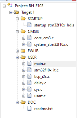
项目结构:
部分代码:
usart.c:
#include "sys.h"
#include "usart.h"


//STM32F103o?D?°?ày3ì
//?aoˉêy°?±?ày3ì
/********** mcudev.taobao.com 3??·  ********/


//
//è?1?ê1ó?ucos,?ò°üà¨????μ?í·???t?′?é.
#if SYSTEM_SUPPORT_UCOS
#include "includes.h"					//ucos ê1ó?
#endif
//
//STM32?a·¢°?
//′??ú13?ê??ˉ

//


//
//?óè?ò???′ú??,?§3?printfoˉêy,??2?Dèòa????use MicroLIB
#if 1
#pragma import(__use_no_semihosting)
//±ê×??aDèòaμ??§3?oˉêy
struct __FILE
{
	int handle;

};

FILE __stdout;
//?¨ò?_sys_exit()ò?±ü?aê1ó?°??÷?ú?£ê?
void _sys_exit(int x)
{
	x = x;
}
//???¨ò?fputcoˉêy
int fputc(int ch, FILE *f)
{
	while((USART1->SR&0X40)==0);//?-?··¢?í,?±μ?·¢?ííê±?
    USART1->DR = (u8) ch;
	return ch;
}
#endif

/*ê1ó?microLibμ?·?·¨*/
 /*
int fputc(int ch, FILE *f)
{
	USART_SendData(USART1, (uint8_t) ch);

	while (USART_GetFlagStatus(USART1, USART_FLAG_TC) == RESET) {}

    return ch;
}
int GetKey (void)  {

    while (!(USART1->SR & USART_FLAG_RXNE));

    return ((int)(USART1->DR & 0x1FF));
}
*/

#if EN_USART1_RX   //è?1?ê1?üá??óê?
//′??ú1?D??·t??3ìDò
//×¢òa,?áè?USARTx->SR?ü±ü?a?a??????μ?′í?ó
u8 USART_RX_BUF[USART_REC_LEN];     //?óê??o3?,×?′óUSART_REC_LEN??×??ú.
//?óê?×′ì?
//bit15£?	?óê?íê3é±ê??
//bit14£?	?óê?μ?0x0d
//bit13~0£?	?óê?μ?μ?óDD§×??úêy??
u16 USART_RX_STA=0;       //?óê?×′ì?±ê??

void uart_init(u32 bound){
    //GPIO???úéè??
  GPIO_InitTypeDef GPIO_InitStructure;
	USART_InitTypeDef USART_InitStructure;
	NVIC_InitTypeDef NVIC_InitStructure;

	RCC_APB2PeriphClockCmd(RCC_APB2Periph_USART1|RCC_APB2Periph_GPIOA, ENABLE);	//ê1?üUSART1£?GPIOAê±?ó
     //USART1_TX   PA.9
    GPIO_InitStructure.GPIO_Pin = GPIO_Pin_9; //PA.9
    GPIO_InitStructure.GPIO_Speed = GPIO_Speed_50MHz;
    GPIO_InitStructure.GPIO_Mode = GPIO_Mode_AF_PP;	//?′ó?í?íìê?3?
    GPIO_Init(GPIOA, &GPIO_InitStructure);

    //USART1_RX	  PA.10
    GPIO_InitStructure.GPIO_Pin = GPIO_Pin_10;
    GPIO_InitStructure.GPIO_Mode = GPIO_Mode_IN_FLOATING;//????ê?è?
    GPIO_Init(GPIOA, &GPIO_InitStructure);

   //Usart1 NVIC ????

    NVIC_InitStructure.NVIC_IRQChannel = USART1_IRQn;
	NVIC_InitStructure.NVIC_IRQChannelPreemptionPriority=3 ;//?à??ó??è??3
	NVIC_InitStructure.NVIC_IRQChannelSubPriority = 3;		//×óó??è??3
	NVIC_InitStructure.NVIC_IRQChannelCmd = ENABLE;			//IRQí¨μàê1?ü
	NVIC_Init(&NVIC_InitStructure);	//?ù?Y???¨μ?2?êy3?ê??ˉVIC??′??÷

   //USART 3?ê??ˉéè??

	USART_InitStructure.USART_BaudRate = bound;//ò?°?éè???a9600;
	USART_InitStructure.USART_WordLength = USART_WordLength_8b;//×?3¤?a8??êy?Y??ê?
	USART_InitStructure.USART_StopBits = USART_StopBits_1;//ò???í£?1??
	USART_InitStructure.USART_Parity = USART_Parity_No;//?T????D£?é??
	USART_InitStructure.USART_HardwareFlowControl = USART_HardwareFlowControl_None;//?Tó2?têy?Yá÷????
	USART_InitStructure.USART_Mode = USART_Mode_Rx | USART_Mode_Tx;	//ê?·¢?£ê?

    USART_Init(USART1, &USART_InitStructure); //3?ê??ˉ′??ú
    USART_ITConfig(USART1, USART_IT_RXNE, ENABLE);//?a???D??
    USART_Cmd(USART1, ENABLE);                    //ê1?ü′??ú

}


void USART1_IRQHandler(void)                	//′??ú1?D??·t??3ìDò
	{
	u8 Res;
#ifdef OS_TICKS_PER_SEC	 	//è?1?ê±?ó?ú??êy?¨ò?á?,?μ?÷òaê1ó?ucosIIá?.
	OSIntEnter();
#endif
	if(USART_GetITStatus(USART1, USART_IT_RXNE) != RESET)  //?óê??D??(?óê?μ?μ?êy?Y±?D?ê?0x0d 0x0a?á?2)
		{
		Res =USART_ReceiveData(USART1);//(USART1->DR);	//?áè??óê?μ?μ?êy?Y

		if((USART_RX_STA&0x8000)==0)//?óê??′íê3é
			{
			if(USART_RX_STA&0x4000)//?óê?μ?á?0x0d
				{
				if(Res!=0x0a)USART_RX_STA=0;//?óê?′í?ó,??D??aê?
				else USART_RX_STA|=0x8000;	//?óê?íê3éá?
				}
			else //?1??ê?μ?0X0D
				{
				if(Res==0x0d)USART_RX_STA|=0x4000;
				else
					{
					USART_RX_BUF[USART_RX_STA&0X3FFF]=Res ;
					USART_RX_STA++;
					if(USART_RX_STA>(USART_REC_LEN-1))USART_RX_STA=0;//?óê?êy?Y′í?ó,??D??aê??óê?
					}
				}
			}
     }
#ifdef OS_TICKS_PER_SEC	 	//è?1?ê±?ó?ú??êy?¨ò?á?,?μ?÷òaê1ó?ucosIIá?.
	OSIntExit();
#endif
}
#endif
完整源码:https://github.com/pilipalaaa/AHT20
编译烧录之后,进行串口调试:


总结
对于I2C通信的过程有了一个初步地了解,需要对不同接口切换高低电频以调整获取信息值。


 4033
4033


 被折叠的 条评论
为什么被折叠?
被折叠的 条评论
为什么被折叠?
 到【灌水乐园】发言


