


一、实验内容e
 二、实验要求
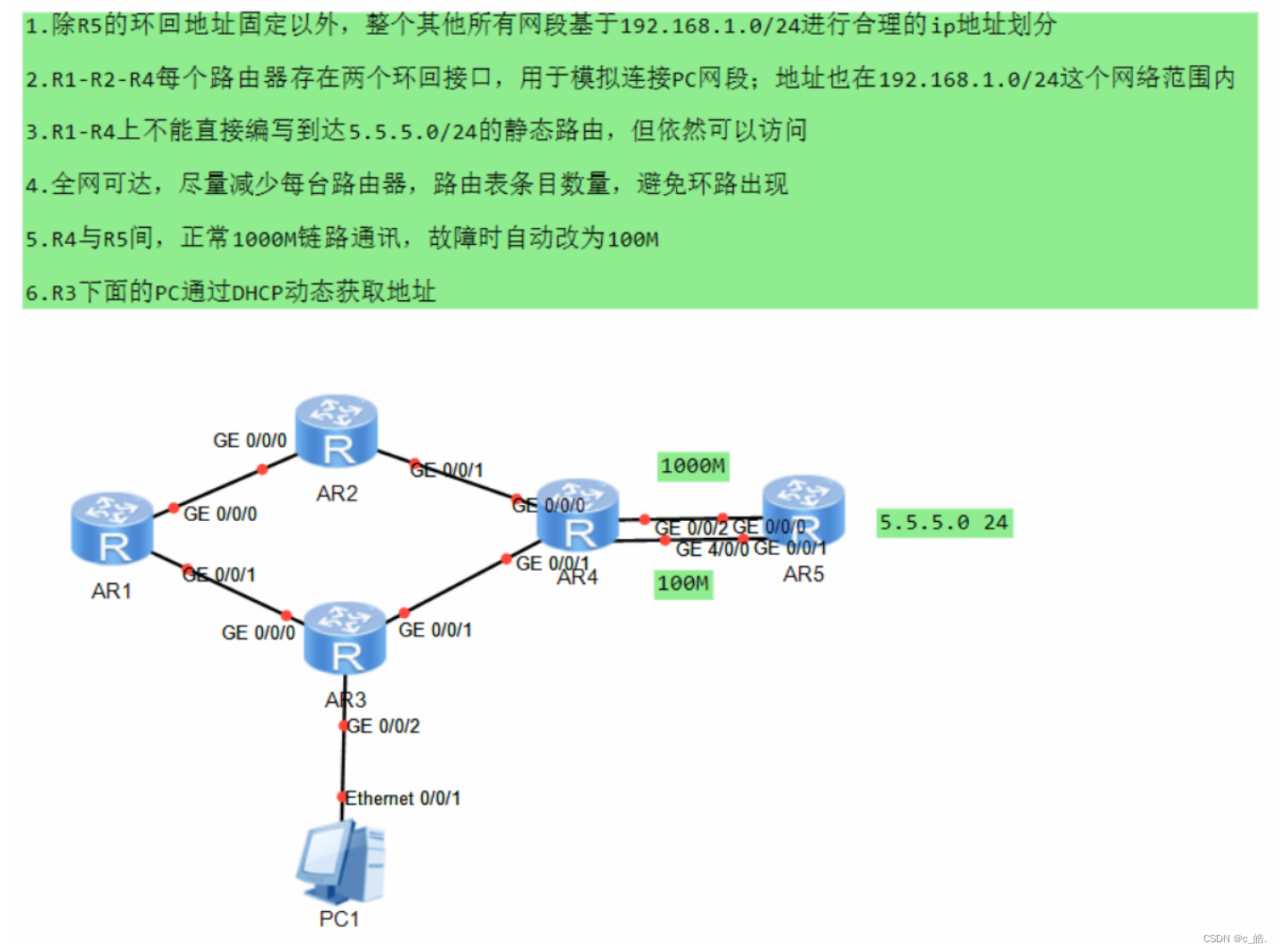
1.除R5的环回地址固定以外,整个其他所有网段基于192.168.1./24进行合理的ip地址划分
2.R1-R2-R4每个路由器存在两个环回接口,用于模拟连接PC网段: 地址也在192.168.1.0/24这个网络范围内
3.R1-R4上不能直接编写到达5.5.5./24的静态路由,但依然可以访问
4.全网可达,尽量减少每台路由器,路由表条目数量,避免环路出现
5.R4与R5间,正常1000M链路通讯,故障时自动改为100M
6.R3下面的Pc通过DHCP动态获取地址
三、实验步骤
1、IP地址划分
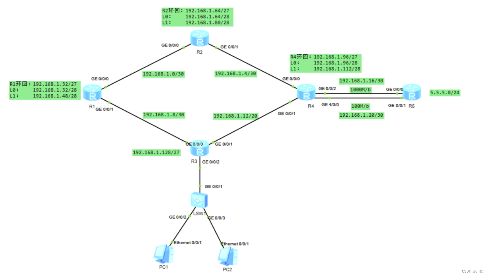
192.168.1.0/24
① 192.168.1.0000 0000/27……骨干链路
1、192.168.1.0000 0000/30……192.168.1.0/30 可用IP:192.168.1.1、192.168.1.2
2、192.168.1.0000 0100/30……192.168.1.4/40 可用IP:192.168.1.5、192.168.1.6
3、192.168.1.0000 1000/30……192.168.1.8/40 可用IP:192.168.1.9、192.168.1.10
4、192.168.1.0000 1100/30……192.168.1.12/40 可用IP:192.168.1.13、192.168.1.14
5、192.168.1.0001 0000/30……192.168.1.16/40 可用IP:192.168.1.17、192.168.1.18
6、192.168.1.0001 0100/30……192.168.1.20/40 可用IP:192.168.1.21、192.168.1.22
7、192.168.1.0001 1000/30
8、192.168.1.0001 1100/30
② 192.168.1.0010 0000/27……R1环回……192.168.1.32/27
1、192.168.1.0010 0000/28……192.168.1.32/28
2、192.168.1.0011 0000/28……192.168.1.48/28
③ 192.168.1.0100 0000/27……R2环回……192.168.1.64/27
1、192.168.1.0100 0000/28……192.168.1.64/28
2、192.168.1.0101 0000/28……192.168.1.80/28
④ 192.168.1.0110 0000/27……R3环回……192.168.1.96/27
1、192.168.1.0110 0000/28……192.168.1.96/28
2、192.168.1.0111 0000/28……192.168.1.112/28
⑤ 192.168.1.1000 0000/27……R4环回……192.168.1.128/27
1、192.168.1.1000 0000/28……192.168.1.128/28
2、192.168.1.1001 0000/28……192.168.1.154/28
⑥ 192.168.1.1010 0000/27
⑦ 192.168.1.1100 0000/27
⑧ 192.168.1.1110 0000/27
2、配置IP地址
R1配置:
[R1]int g0/0/0
[R1-GigabitEthernet0/0/0]ip address 192.168.1.1 30 //配置0/0/0接口
[R1-GigabitEthernet0/0/0]q
[R1]int g0/0/1
[R1-GigabitEthernet0/0/1]ip address 192.168.1.9 30 //配置0/0/1接口
[R1-GigabitEthernet0/0/1]q
[R1]interface LoopBack 0
[R1-LoopBack0]ip address 192.168.1.33 28 //配置R1的环回接口L0
[R1]interface LoopBack 1
[R1-LoopBack1]ip address 192.168.1.49 28 //配置R1的环回接口L1
R2配置:
[R2]int g0/0/0
[R2-GigabitEthernet0/0/0]ip address 192.168.1.2 30 //配置0/0/0接口
[R2]int g0/0/1
[R2-GigabitEthernet0/0/1]ip address 192.168.1.5 30 //配置0/0/1接口
[R2-GigabitEthernet0/0/1]q
[R2]interface LoopBack 0
[R2-LoopBack0]ip address 192.168.1.65 28 //配置R2的环回接口L0
[R2]interface LoopBack 1
[R2-LoopBack2]ip address 192.168.1.81 28 //配置R2的环回接口L1
R3配置:
[R3]int g0/0/0
[R3-GigabitEthernet0/0/0]ip address 192.168.1.10 30 //配置0/0/0接口
[R3-GigabitEthernet0/0/0]int g0/0/1
[R3-GigabitEthernet0/0/1]ip address 192.168.1.12 30 //配置0/0/1接口
[R3-GigabitEthernet0/0/1]int g0/0/2
[R3-GigabitEthernet0/0/2]ip add 192.168.1.129 27 //配置0/0/2接口
R4配置:
[R4]int g0/0/0
[R4-GigabitEthernet0/0/0]ip address 192.168.1.6 30 //配置0/0/0接口
[R4-GigabitEthernet0/0/0]int g0/0/1
[R4-GigabitEthernet0/0/1]ip address 192.168.1.14 30 //配置0/0/1接口
[R4-GigabitEthernet0/0/0]int g0/0/2
[R4-GigabitEthernet0/0/2]ip address 192.168.1.17 30 //配置0/0/2接口
[R4-GigabitEthernet0/0/2]int g 4/0/0
[R4-GigabitEthernet4/0/0]ip address 192.168.1.21 30 //配置4/0/0接口
[R4-GigabitEthernet0/0/1]q
[R4]interface LoopBack 0
[R4-LoopBack0]ip address 192.168.1.97 28 //配置R2的环回接口L0
[R4-LoopBack0]interface LoopBack 1
[R4-LoopBack1]ip address 192.168.1.113 28 //配置R2的环回接口L1
R5配置:
[R5]int g0/0/0
[R5-GigabitEthernet0/0/0]ip address 192.168.1.18 30 //配置0/0/0接口
[R5-GigabitEthernet0/0/0]int g0/0/1
[R5-GigabitEthernet0/0/1]ip address 192.168.1.22 30 //配置0/0/1接口
[R5-GigabitEthernet0/0/1]q
[R5]interface LoopBack 0
[R5-LoopBack0]ip address 5.5.5.5 24 //配置R5的环回地址
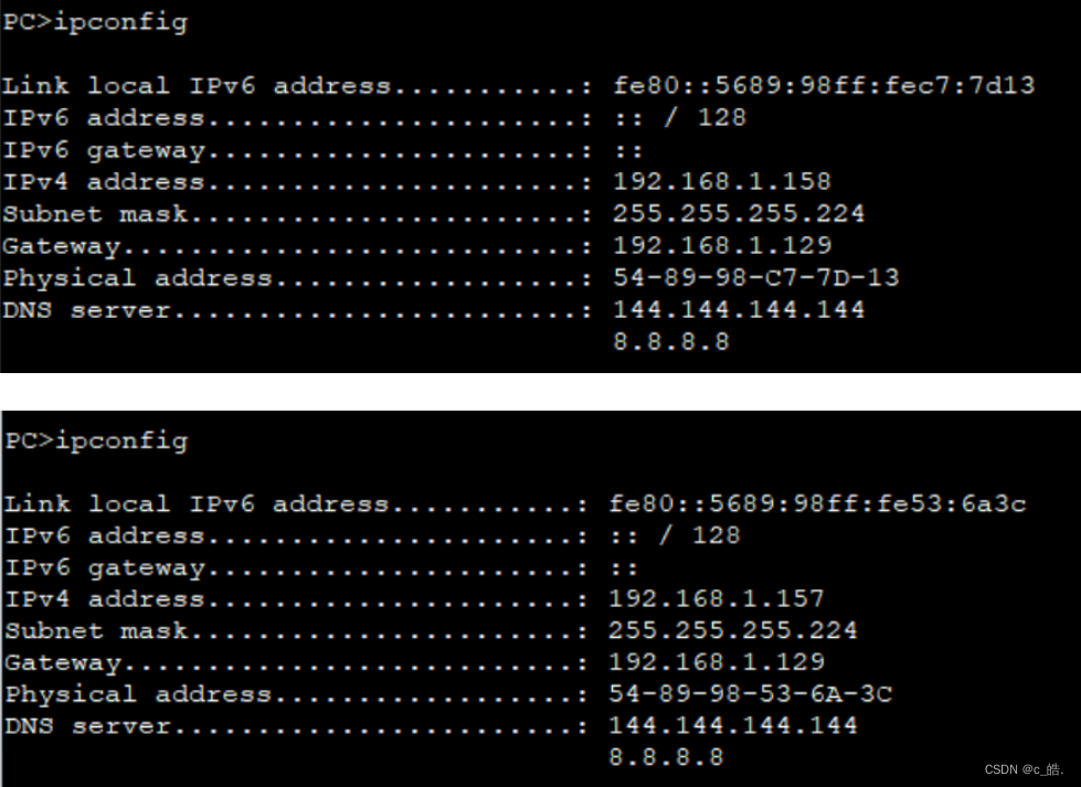
3、DHCP自动配置IP地址
[R3]dhcp enable
[R3]ip pool a
[R3-ip-pool-a]network 192.168.1.128 mask 27
[R3-ip-pool-a]gateway-list 192.168.1.129
[R3-ip-pool-a]dns-list 144.144.144.144 8.8.8.8
[R3-ip-pool-a]q
[R3]int g0/0/2
[R3-GigabitEthernet0/0/2]dhcp select global
[R3-GigabitEthernet0/0/2]q
4、 配置静态路由
以R1为例,其余同理
[R1]ip route-static 192.168.1.4 30 192.168.1.2
[R1]ip route-static 192.168.1.64 27 192.168.1.2
[R1]ip route-static 192.168.1.96 27 192.168.1.2
[R1]ip route-static 192.168.1.96 27 192.168.1.10
[R1]ip route-static 192.168.1.16 30 192.168.1.2
[R1]ip route-static 192.168.1.16 30 192.168.1.10
[R1]ip route-static 192.168.1.20 30 192.168.1.10
[R1]ip route-static 192.168.1.20 30 192.168.1.2
[R1]ip route-static 192.168.1.12 30 192.168.1.10
[R1]ip route-static 192.168.1.128 27 192.168.1.10
5、配置缺省路由
R1:
[R1]ip route-static 0.0.0.0 0 192.168.1.2
[R1]ip route-static 0.0.0.0 0 192.168.1.10
R2:
[R2]ip route-static 0.0.0.0 0 192.168.1.6
R3:
[R3]ip route-static 0.0.0.0 0 192.168.1.14
R4:
[R4]ip route-static 0.0.0.0 0 192.168.1.18
[R4]ip route-static 0.0.0.0 0 192.168.1.22
6、 加上空接口防环路由
R1:
[R1]ip route-static 192.168.1.32 27 NULL0
R2:
[R2]ip route-static 192.168.1.64 27 NULL0
R3:
[R3]ip route-static 192.168.1.128 27 NULL0
R4:
[R4]ip route-static 192.168.1.96 27 NULL0
7、配置浮动路由
R4调整优先级:
[R4]ip route-static 0.0.0.0 0 192.168.1.22 preference 61
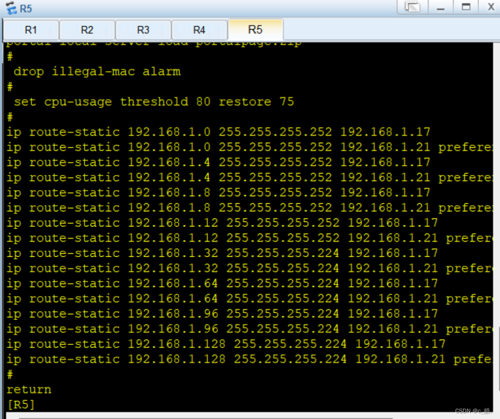
R5调整优先级:
ip route-static 192.168.1.128 27 192.168.1.21 preference 61
ip route-static 192.168.1.12 30 192.168.1.21 preference 61
ip route-static 192.168.1.96 27 192.168.1.21 preference 61
ip route-static 192.168.1.4 30 192.168.1.21 preference 61
ip route-static 192.168.1.32 27 192.168.1.21 preference 61
ip route-static 192.168.1.0 30 192.168.1.21 preference 61
ip route-static 192.168.1.64 27 192.168.1.21 preference 61
ip route-static 192.168.1.8 30 192.168.1.21 preference 61
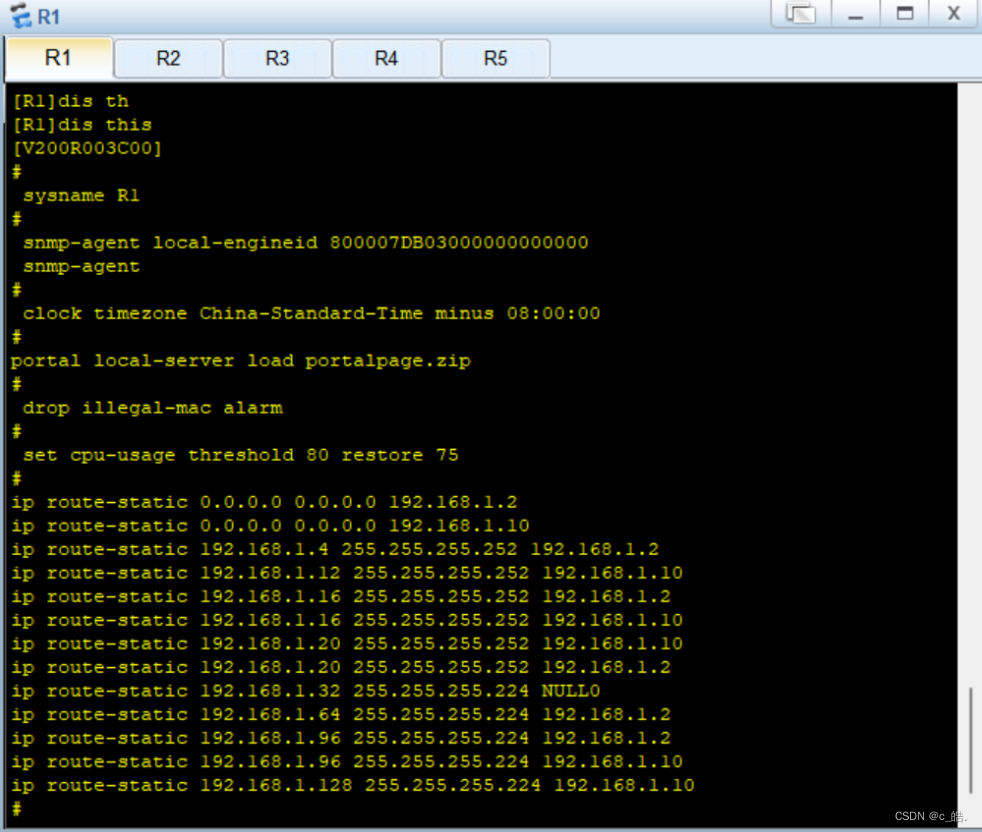
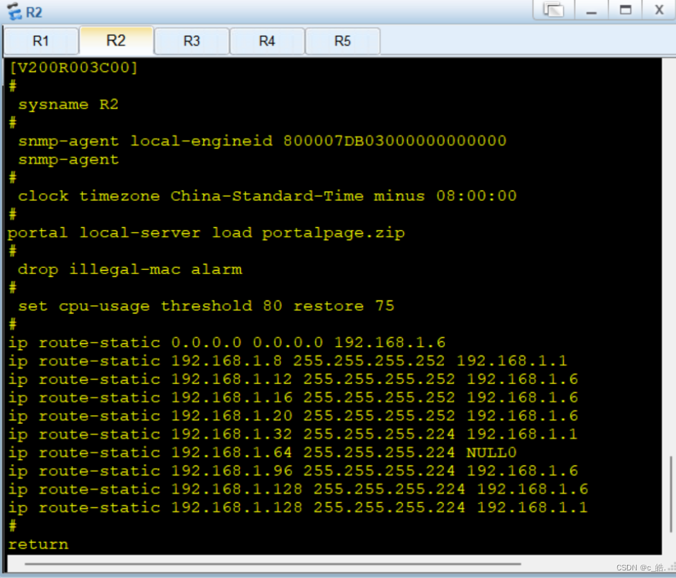
8、 路由器表如下
以R1、R2、R5为例:
 9、全网通测试
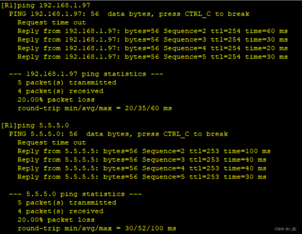 10、PC端动态获取IP结果
 注意:
注意:
1.普通网段进行常规配置即可,为了方便简洁对部分网段进行了子网汇总。
2.由于R1-R4上不能直接写到达5.5.5.0/24的静态路由,因此要为其配置缺省路由,使未匹配的数据包指向5.5.5.0/24。
3.浮动路由配置
利用ip route-static x.x.x.x ?? y.y.y.y preference [?]来改变静态路由的优先级
preference 值越大优先级越低


 716
716


 被折叠的 条评论
为什么被折叠?
被折叠的 条评论
为什么被折叠?
 到【灌水乐园】发言


