


第一步: 搭建拓扑,地址规划。

第二步,配置地址,静态路由,公网物理可达
[R1]int s4/0/0
[R1-Serial4/0/0]ip add 15.0.0.1 24
[R1-Serial4/0/0]int g0/0/0
[R1-GigabitEthernet0/0/0]ip add 192.168.1.254 24

[R2]int g0/0/0
[R2-GigabitEthernet0/0/0]ip add 192.168.2.254 24
[R2-GigabitEthernet0/0/0]int s4/0/0
[R2-Serial4/0/0]ip add 25.0.0.1 24

[R3]int g0/0/0
[R3-GigabitEthernet0/0/0]ip add 192.168.3.254 24
[R3-GigabitEthernet0/0/0]int s4/0/0
[R3-Serial4/0/0]ip add 35.0.0.1 24

[R4]int g0/0/0
[R4-GigabitEthernet0/0/0]ip add 45.0.0.1 24
[R4-GigabitEthernet0/0/0]int g0/0/1
[R4-GigabitEthernet0/0/1]ip add 192.168.4.254 24

[ISP]int s3/0/0
[ISP-Serial3/0/0]ip add 15.0.0.2 24
[ISP-Serial3/0/0]int s3/0/1
[ISP-Serial3/0/1]ip add 25.0.0.2 24
[ISP-Serial3/0/1]int s4/0/0
[ISP-Serial4/0/0]ip add 35.0.0.2 24
[ISP-Serial4/0/0]int g0/0/0
[ISP-GigabitEthernet0/0/0]ip add 45.0.0.2 24
[ISP-GigabitEthernet0/0/0]int l0
[ISP-LoopBack0]ip add 5.5.5.5 24
测试联通:
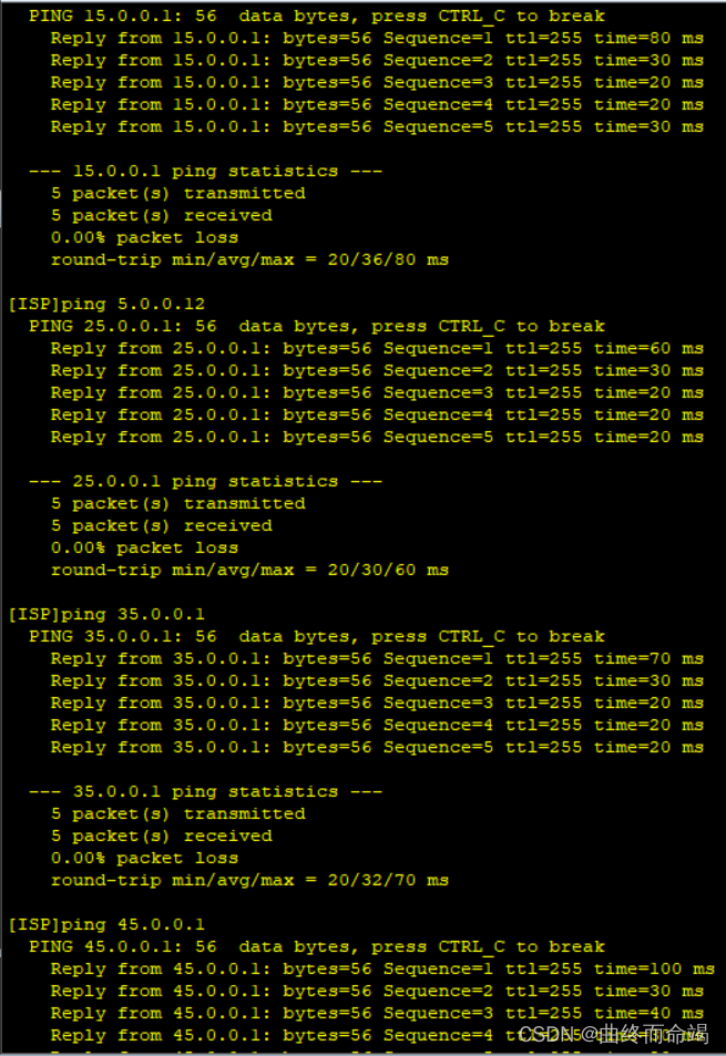
缺省指向ISP:
[R1]ip route-static 0.0.0.0 0 15.0.0.2

[R2]ip route-static 0.0.0.0 0 25.0.0.2

[R3]ip route-static 0.0.0.0 0 35.0.0.2

[R4]ip route-static 0.0.0.0 0 45.0.0.2
测试:
第三步:认证
R1和R5之间使用PPP的PAP认证,R5为主认证方
[ISP]aaa
[ISP-aaa]local-user huawei pass ciph 666666
[ISP-aaa]local-user huawei service-type ppp
[ISP-aaa]q
[ISP]int s3/0/0
[ISP-Serial3/0/0]ppp authentication-mode pap

[R1]int s4/0/0
[R1-Serial4/0/0]ppp pap local-user huawei password cipher 666666
R2和R5之间使用PPP的CHAP认证,R5为主认证方
[ISP]aaa
[ISP-aaa]local-user ccip pass ciph 777777
[ISP-aaa]local-user ccip service-type ppp
[ISP-aaa]q
[ISP]int s3/0/1
[ISP-Serial3/0/1]ppp authentication-mode chap

[R2]int s4/0/0
[R2-Serial4/0/0]ppp chap user ccip
[R2-Serial4/0/0]ppp chap password cipher 777777
PAP和CHAP认证需要接口重启,重新进行连接
R3和R5之间使用HDLC封装
[R3]int s4/0/0
[R3-Serial4/0/0]link-protocol hdlc

[ISP-Serial3/0/1]int s4/0/0
[ISP-Serial4/0/0]link-protocol hdlc
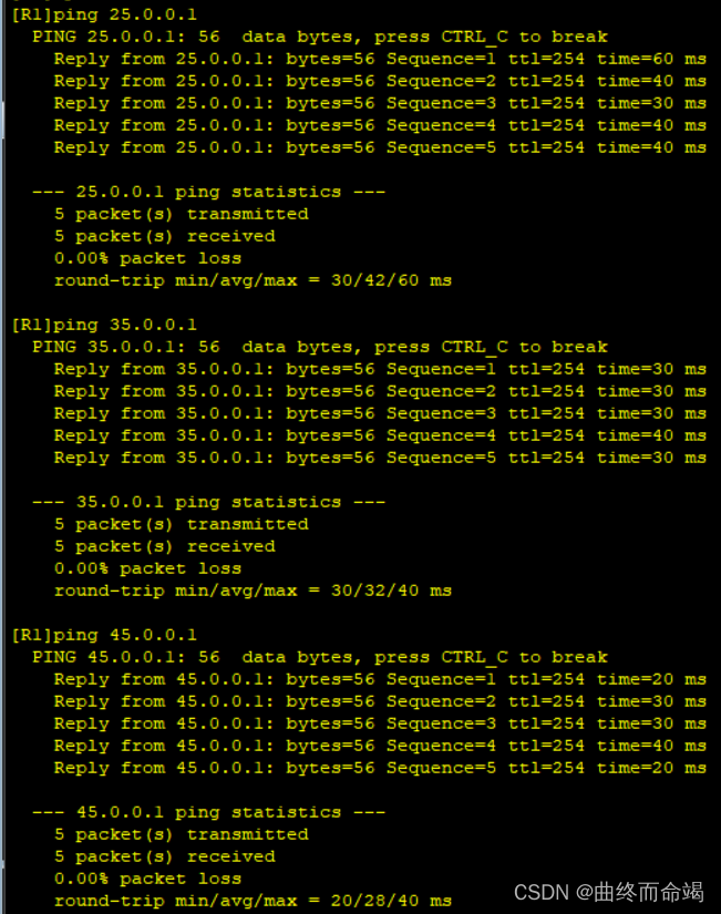
测试联通:

第四步,GRE环境搭建
R1/R2/R3构建一个MGRE环境,R1为HUB。
[R1]int t0/0/0
[R1-Tunnel0/0/0]ip add 192.168.5.1 24
[R1-Tunnel0/0/0]tunnel-protocol gre p2mp
[R1-Tunnel0/0/0]source 15.0.0.1

[R2]int t0/0/0
[R2-Tunnel0/0/0]ip add 192.168.5.2 24
[R2-Tunnel0/0/0]tunnel-protocol gre p2mp
[R2-Tunnel0/0/0]source s4/0/0
[R2-Tunnel0/0/0]nhrp entry 192.168.5.1 15.0.0.1 register

[R3]int t0/0/0
[R3-Tunnel0/0/0]ip add 192.168.5.3 24
[R3-Tunnel0/0/0]tunnel-protocol gre p2mp
[R3-Tunnel0/0/0]source s4/0/0
[R3-Tunnel0/0/0]nhrp entry 192.168.5.1 15.0.0.1 re
R1/R4之间构建一个GRE环境
[R1]int t0/0/1
[R1-Tunnel0/0/1]ip add 192.168.6.1 24
[R1-Tunnel0/0/1]tunnel-protocol gre
[R1-Tunnel0/0/1]source 15.0.0.1
[R1-Tunnel0/0/1]destination 45.0.0.1

[R4]int t0/0/0
[R4-Tunnel0/0/0]ip add 192.168.6.2 24
[R4-Tunnel0/0/0]tunnel-protocol gre
[R4-Tunnel0/0/0]source 45.0.0.1
[R4-Tunnel0/0/0]destination 15.0.0.1
第五步:动态路由协议RIP
[R1]rip 1
[R1-rip-1]v 2
[R1-rip-1]undo su
[R1-rip-1]undo summary
[R1-rip-1]network 192.168.1.0
[R1-rip-1]network 192.168.5.0
[R1-rip-1]network 192.168.6.0

[R2]rip 1
[R2-rip-1]v 2
[R2-rip-1]undo sum
[R2-rip-1]network 192.168.2.0
[R2-rip-1]network 192.168.5.0

[R3]rip 1
[R3-rip-1]v 2
[R3-rip-1]undo sum
[R3-rip-1]network 192.168.3.0
[R3-rip-1]network 192.168.5.0

[R4]rip 1
[R4-rip-1]v 2
[R4-rip-1]undo sum
[R4-rip-1]network 192.168.4.0
[R4-rip-1]network 192.168.6.0
查看路由表:


很明显,只有中心学到了其他人的路由:
[R1]int s4/0/0
[R1-Serial4/0/0]rip summary-address 192.168.0.0 255.255.252.0
[R1-Serial4/0/0]int t0/0/0
[R1-Tunnel0/0/0]nhrp entry multicast dynamic
[R1-Tunnel0/0/0]nhrp redirect

[R2]int t0/0/0
[R2-Tunnel0/0/0]nhrp shortcut

[R3]int t0/0/0
[R3-Tunnel0/0/0]nhrp shortcut

第六步:NAT
[R1]acl 2000
[R1-acl-basic-2000]rule permit source 192.168.1.0 0.0.0.255
[R1-acl-basic-2000]int s4/0/0
[R1-Serial4/0/0]nat outbound 2000

[R2]acl 2000
[R2-acl-basic-2000]rule permit source 192.168.2.0 0.0.0.255
[R2-acl-basic-2000]int s4/0/0
[R2-Serial4/0/0]nat outbound 2000

[R3]acl 2000
[R3-acl-basic-2000]rule permit source 192.168.3.0 0.0.0.255
[R3-acl-basic-2000]int s4/0/0
[R3-Serial4/0/0]nat outbound 2000

[R4]acl 2000
[R4-acl-basic-2000]rule permit source 192.168.4.0 0.0.0.255
[R4-acl-basic-2000]int g0/0/0
[R4-GigabitEthernet0/0/0]nat outbound 2000
第七步:配置主机,全网可达测试


全网可达测试: 


 306
306


 被折叠的 条评论
为什么被折叠?
被折叠的 条评论
为什么被折叠?
 到【灌水乐园】发言


