


基于STM32的智能鱼缸控制系统设计
摘要:
随着物联网技术的飞速发展,智能家居产品日益丰富,智能鱼缸作为其中的一种,不仅能够提供观赏价值,还能通过智能化管理提升养鱼体验。本文设计了一种基于STM32单片机的智能鱼缸控制系统,该系统集成了0.96寸OLED显示模块、浊度传感器、DS18B20温度传感器、DS1302实时时钟模块、蓝牙通信模块以及光照检测模块,实现了对鱼缸水质的实时监测、水温的智能调控、远程操作控制、定时喂鱼以及光照强度的显示与传输等功能。通过该系统,用户可以方便地了解鱼缸内环境状况,并根据需要进行远程干预,极大地提高了养鱼的便捷性和科学性。
关键词:STM32;智能鱼缸;水质监测;温度控制;蓝牙通信;光照检测
Abstract:
With the rapid development of the Internet of Things technology, smart home products are becoming increasingly diverse. As one of them, smart aquariums not only provide ornamental value but also enhance the fishkeeping experience through intelligent management. This paper designs a smart aquarium control system based on the STM32 microcontroller, which integrates a 0.96-inch OLED display module, turbidity sensor, DS18B20 temperature sensor, DS1302 real-time clock module, Bluetooth communication module, and light intensity detection module. The system realizes real-time monitoring of aquarium water quality, intelligent temperature control, remote operation and control, timed feeding, and display and transmission of light intensity. With this system, users can easily understand the environmental conditions inside the aquarium and intervene remotely as needed, greatly improving the convenience and scientific nature of fishkeeping.
Keywords: STM32; Smart Aquarium; Water Quality Monitoring; Temperature Control; Bluetooth Communication; Light Intensity Detection
第一章 引言
1.1 研究背景与意义
随着人们生活水平的提高,越来越多的人开始追求精神生活的丰富,养鱼作为一种传统的休闲方式,受到了越来越多人的喜爱。然而,传统鱼缸的管理往往依赖于人工观察与操作,不仅耗时费力,还难以保证鱼缸环境的稳定与适宜。因此,开发一种能够自动监测并调节鱼缸环境的智能鱼缸控制系统显得尤为重要。
智能鱼缸控制系统通过集成多种传感器与执行器,能够实时监测鱼缸内的水质、水温、光照等关键参数,并根据预设条件自动执行换水、加热、喂鱼等操作,从而实现对鱼缸环境的智能化管理。此外,通过蓝牙等无线通信模块,用户还可以远程查看鱼缸状态并进行操作,极大地提高了养鱼的便捷性和乐趣。
1.2 国内外研究现状
目前,国内外已有不少关于智能鱼缸控制系统的研究与应用。国外方面,一些高端鱼缸品牌已经推出了具备智能管理功能的鱼缸产品,如德国的Juwel、美国的Tetra等品牌,这些产品通常集成了水质监测、温度控制、自动喂食等功能,但价格较高,普及率有限。国内方面,随着物联网技术的快速发展,越来越多的企业和科研机构开始涉足智能鱼缸控制系统的研发,推出了一系列性价比更高的智能鱼缸产品。然而,这些产品大多存在功能单一、智能化程度不足等问题,难以满足用户多样化的需求。
1.3 论文结构
本文共分为六章,各章内容安排如下:
第一章:引言,介绍研究背景与意义、国内外研究现状及论文结构。
第二章:系统总体设计,阐述系统的主要功能、硬件组成及软件架构。
第三章:硬件设计,详细介绍各硬件模块的选择、电路设计及连接方法。
第四章:软件设计,包括STM32程序设计、传感器数据采集与处理、蓝牙通信协议设计等。
第五章:系统测试与性能分析,对系统进行功能测试、性能测试及用户体验评估。
第六章:结论与展望,总结研究成果,提出改进建议及未来研究方向。
第二章 系统总体设计
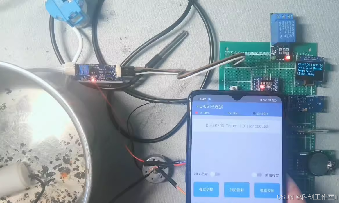
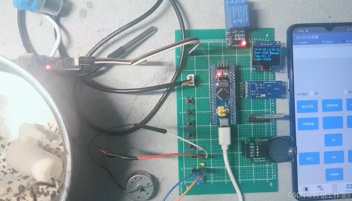
2.1 系统主要功能
本系统旨在实现以下主要功能:
-
水质监测与自动换水:通过浊度传感器实时监测鱼缸水质状态,当水质低于设定值时,自动启动水泵进行换水操作。
-
水温监测与智能加热:利用DS18B20温度传感器监测鱼缸水温,并根据用户设定的阈值自动开启或关闭加热装置,保持水温在适宜范围内。
-
远程操作与控制:通过蓝牙模块实现与手机APP的通信,用户可远程查看鱼缸状态(包括水温、浊度、光照强度等),并切换自动/手动模式,在手动模式下支持开启或关闭加热、换水、喂鱼等操作。
-
实时时钟与定时喂鱼:采用DS1302实时时钟模块,实现时间显示与定时功能,用户可设置喂鱼时间,系统到时自动执行喂鱼操作(采用电机模拟)。
-
光照检测与显示:通过光照传感器实时监测鱼缸内光照强度,并在OLED屏幕上显示,同时通过蓝牙发送至手机端。
2.2 硬件组成
系统硬件主要由STM32单片机、0.96寸OLED显示模块、浊度传感器、DS18B20温度传感器、DS1302实时时钟模块、蓝牙通信模块、光照传感器、水泵、加热装置(继电器模拟)、喂鱼电机等部分组成。
2.3 软件架构
系统软件架构主要包括STM32固件开发环境(如Keil或IAR)、传感器数据采集与处理程序、蓝牙通信程序、OLED显示程序、实时时钟与定时喂鱼程序等。各模块之间通过STM32单片机的内部总线进行通信与数据交换,实现系统的整体功能。
第三章 硬件设计
3.1 STM32单片机选型与电路设计
本系统选用STM32F103系列单片机作为控制核心,该系列单片机具有丰富的外设资源、强大的数据处理能力及低功耗特性,能够满足系统的需求。电路设计方面,主要包括STM32单片机的最小系统电路(包括电源电路、复位电路、时钟电路等)、各传感器与执行器的接口电路等。
3.2 OLED显示模块设计
选用0.96寸OLED显示屏作为系统的显示模块,该模块具有体积小、功耗低、显示效果好等优点。通过I2C或SPI接口与STM32单片机连接,实现数据的显示与刷新。在软件设计上,需要编写OLED驱动程序,包括初始化程序、字符显示程序、图形显示程序等。
3.3 浊度传感器设计
浊度传感器用于实时监测鱼缸水质状态。本系统选用光散射式浊度传感器,通过测量光线穿过水样后的散射程度来反映水质的浊度。传感器输出模拟信号,通过STM32单片机的ADC模块进行采集与处理。在软件设计上,需要编写ADC采集程序及浊度计算程序。
3.4 DS18B20温度传感器设计
DS18B20是一款单总线数字温度传感器,具有测量精度高、抗干扰能力强等优点。通过单总线接口与STM32单片机连接,实现温度的采集与传输。在软件设计上,需要编写DS18B20驱动程序,包括初始化程序、温度读取程序等。
3.5 DS1302实时时钟模块设计
DS1302是一款低功耗、高性能的实时时钟芯片,具有年、月、日、时、分、秒等时间信息存储功能。通过SPI接口与STM32单片机连接,实现时间的读取与设置。在软件设计上,需要编写DS1302驱动程序,包括初始化程序、时间读取与设置程序等。
3.6 蓝牙通信模块设计
选用蓝牙模块(如HC-05或HC-06)作为系统的无线通信模块,实现与手机APP的通信。蓝牙模块通过UART接口与STM32单片机连接,实现数据的发送与接收。在软件设计上,需要编写蓝牙通信程序,包括初始化程序、数据发送与接收程序等。同时,需要开发手机APP,实现与蓝牙模块的通信及数据的显示与控制。
3.7 光照传感器与执行器设计
光照传感器用于实时监测鱼缸内光照强度。本系统选用光敏电阻作为光照传感器,通过测量光敏电阻的阻值变化来反映光照强度的变化。传感器输出模拟信号,通过STM32单片机的ADC模块进行采集与处理。在软件设计上,需要编写ADC采集程序及光照强度计算程序。执行器方面,包括水泵、加热装置(继电器模拟)、喂鱼电机等,通过GPIO口控制其开关状态。
第四章 软件设计
4.1 STM32程序设计
STM32程序设计是系统实现的核心部分,包括系统初始化、各模块驱动程序编写、数据处理与逻辑控制等。在程序设计中,需要充分考虑系统的实时性、稳定性和可扩展性。采用模块化设计思想,将各功能模块封装为独立的函数或模块,便于代码的调试与维护。
4.2 传感器数据采集与处理
传感器数据采集与处理是系统实现的基础。通过STM32单片机的ADC模块采集浊度传感器和光照传感器的模拟信号,并进行滤波、放大等预处理;通过单总线接口读取DS18B20温度传感器的温度数据;通过SPI接口读取DS1302实时时钟模块的时间数据。在数据处理方面,需要对采集到的数据进行滤波、校准等处理,以提高数据的准确性和可靠性。
4.3 蓝牙通信协议设计
蓝牙通信协议设计是实现远程操作与控制的关键。本系统采用自定义的蓝牙通信协议,包括数据帧格式、校验码、命令码等。在协议设计中,需要充分考虑数据的完整性、准确性和安全性。同时,需要编写手机APP,实现与蓝牙模块的通信及数据的显示与控制。手机APP采用Android或iOS平台开发,具有友好的
用户界面和丰富的功能。
4.4 OLED显示程序设计
OLED显示程序设计负责将鱼缸的各项参数(如水温、浊度、光照强度、时间等)实时显示在屏幕上。程序设计时,需要考虑到信息的清晰度和可读性,合理安排显示内容和布局。同时,为了提高显示效果的流畅性,需要优化屏幕刷新速率和数据处理速度。
4.5 实时时钟与定时喂鱼程序设计
实时时钟程序设计负责读取和设置DS1302模块的时间信息,确保系统时间的准确性。定时喂鱼程序设计则根据用户设定的喂鱼时间,自动触发喂鱼操作。在程序设计中,需要考虑到时间的精确性和喂鱼操作的可靠性,确保在设定的时间准确执行喂鱼任务。
第五章 系统测试与性能分析
5.1 系统功能测试
系统功能测试是验证系统是否满足设计要求的重要环节。测试内容包括水质监测与自动换水功能、水温监测与智能加热功能、远程操作与控制功能、实时时钟与定时喂鱼功能以及光照检测与显示功能等。测试过程中,需要记录各项功能的执行情况和数据结果,分析是否存在异常或不符合预期的情况。
5.2 系统性能测试
系统性能测试主要评估系统的稳定性、实时性和准确性等关键性能指标。稳定性测试通过长时间运行系统,观察是否出现崩溃、卡顿等异常情况;实时性测试通过模拟实时操作,评估系统响应时间和数据处理速度;准确性测试则通过对比传感器采集的数据与实际值,评估系统的测量精度和误差范围。
5.3 用户体验评估
用户体验评估是评估系统易用性和用户满意度的重要环节。通过邀请一定数量的用户进行试用,并收集他们的反馈意见,分析系统在用户界面、操作流程、功能设置等方面的优缺点,提出改进建议。
第六章 结论与展望
6.1 结论
本文设计了一种基于STM32单片机的智能鱼缸控制系统,通过集成多种传感器与执行器,实现了对鱼缸环境的智能化管理。系统具有水质监测与自动换水、水温监测与智能加热、远程操作与控制、实时时钟与定时喂鱼以及光照检测与显示等功能。经过测试与评估,系统表现出良好的稳定性、实时性和准确性,能够满足用户多样化的需求。
6.2 改进建议
尽管本系统已经实现了基本的智能化管理功能,但在实际应用中仍存在一些不足之处。例如,系统的扩展性有待提升,以便支持更多种类的传感器和执行器;用户界面的友好性和易用性可以进一步优化,提高用户的操作体验;同时,系统的功耗和成本也需要进一步降低,以提高其市场竞争力。
6.3 未来研究方向
未来的研究可以围绕以下几个方面展开:一是探索更加先进的传感器技术和数据处理算法,提高系统的测量精度和智能化水平;二是研究更加高效、节能的电源管理方案,降低系统的功耗;三是开发更加丰富的用户交互功能和远程控制手段,提升用户的养鱼体验和乐趣;四是探索将智能鱼缸控制系统与其他智能家居设备进行联动和集成,构建更加完善的智能家居生态系统。
综上所述,本文设计的基于STM32的智能鱼缸控制系统为养鱼爱好者提供了一种便捷、科学的养鱼方式,具有重要的实际应用价值和推广意义。未来,随着物联网技术的不断发展和智能家居市场的不断扩大,智能鱼缸控制系统将迎来更加广阔的发展前景和应用空间。
/**
******************************************************************************
* @file stm32f10x_usart.c
* @author MCD Application Team
* @version V3.5.0
* @date 11-March-2011
* @brief This file provides all the USART firmware functions.
******************************************************************************
* @attention
*
* THE PRESENT FIRMWARE WHICH IS FOR GUIDANCE ONLY AIMS AT PROVIDING CUSTOMERS
* WITH CODING INFORMATION REGARDING THEIR PRODUCTS IN ORDER FOR THEM TO SAVE
* TIME. AS A RESULT, STMICROELECTRONICS SHALL NOT BE HELD LIABLE FOR ANY
* DIRECT, INDIRECT OR CONSEQUENTIAL DAMAGES WITH RESPECT TO ANY CLAIMS ARISING
* FROM THE CONTENT OF SUCH FIRMWARE AND/OR THE USE MADE BY CUSTOMERS OF THE
* CODING INFORMATION CONTAINED HEREIN IN CONNECTION WITH THEIR PRODUCTS.
*
* <h2><center>© COPYRIGHT 2011 STMicroelectronics</center></h2>
******************************************************************************
*/
/* Includes ------------------------------------------------------------------*/
#include "stm32f10x_usart.h"
#include "stm32f10x_rcc.h"
/** @addtogroup STM32F10x_StdPeriph_Driver
* @{
*/
/** @defgroup USART
* @brief USART driver modules
* @{
*/
/** @defgroup USART_Private_TypesDefinitions
* @{
*/
/**
* @}
*/
/** @defgroup USART_Private_Defines
* @{
*/
#define CR1_UE_Set ((uint16_t)0x2000) /*!< USART Enable Mask */
#define CR1_UE_Reset ((uint16_t)0xDFFF) /*!< USART Disable Mask */
#define CR1_WAKE_Mask ((uint16_t)0xF7FF) /*!< USART WakeUp Method Mask */
#define CR1_RWU_Set ((uint16_t)0x0002) /*!< USART mute mode Enable Mask */
#define CR1_RWU_Reset ((uint16_t)0xFFFD) /*!< USART mute mode Enable Mask */
#define CR1_SBK_Set ((uint16_t)0x0001) /*!< USART Break Character send Mask */
#define CR1_CLEAR_Mask ((uint16_t)0xE9F3) /*!< USART CR1 Mask */
#define CR2_Address_Mask ((uint16_t)0xFFF0) /*!< USART address Mask */
#define CR2_LINEN_Set ((uint16_t)0x4000) /*!< USART LIN Enable Mask */
#define CR2_LINEN_Reset ((uint16_t)0xBFFF) /*!< USART LIN Disable Mask */
#define CR2_LBDL_Mask ((uint16_t)0xFFDF) /*!< USART LIN Break detection Mask */
#define CR2_STOP_CLEAR_Mask ((uint16_t)0xCFFF) /*!< USART CR2 STOP Bits Mask */
#define CR2_CLOCK_CLEAR_Mask ((uint16_t)0xF0FF) /*!< USART CR2 Clock Mask */
#define CR3_SCEN_Set ((uint16_t)0x0020) /*!< USART SC Enable Mask */
#define CR3_SCEN_Reset ((uint16_t)0xFFDF) /*!< USART SC Disable Mask */
#define CR3_NACK_Set ((uint16_t)0x0010) /*!< USART SC NACK Enable Mask */
#define CR3_NACK_Reset ((uint16_t)0xFFEF) /*!< USART SC NACK Disable Mask */
#define CR3_HDSEL_Set ((uint16_t)0x0008) /*!< USART Half-Duplex Enable Mask */
#define CR3_HDSEL_Reset ((uint16_t)0xFFF7) /*!< USART Half-Duplex Disable Mask */
#define CR3_IRLP_Mask ((uint16_t)0xFFFB) /*!< USART IrDA LowPower mode Mask */
#define CR3_CLEAR_Mask ((uint16_t)0xFCFF) /*!< USART CR3 Mask */
#define CR3_IREN_Set ((uint16_t)0x0002) /*!< USART IrDA Enable Mask */
#define CR3_IREN_Reset ((uint16_t)0xFFFD) /*!< USART IrDA Disable Mask */
#define GTPR_LSB_Mask ((uint16_t)0x00FF) /*!< Guard Time Register LSB Mask */
#define GTPR_MSB_Mask ((uint16_t)0xFF00) /*!< Guard Time Register MSB Mask */
#define IT_Mask ((uint16_t)0x001F) /*!< USART Interrupt Mask */
/* USART OverSampling-8 Mask */
#define CR1_OVER8_Set ((u16)0x8000) /* USART OVER8 mode Enable Mask */
#define CR1_OVER8_Reset ((u16)0x7FFF) /* USART OVER8 mode Disable Mask */
/* USART One Bit Sampling Mask */
#define CR3_ONEBITE_Set ((u16)0x0800) /* USART ONEBITE mode Enable Mask */
#define CR3_ONEBITE_Reset ((u16)0xF7FF) /* USART ONEBITE mode Disable Mask */
/**
* @}
*/
/** @defgroup USART_Private_Macros
* @{
*/
/**
* @}
*/
/** @defgroup USART_Private_Variables
* @{
*/
/**
* @}
*/
/** @defgroup USART_Private_FunctionPrototypes
* @{
*/
/**
* @}
*/
/** @defgroup USART_Private_Functions
* @{
*/
/**
* @brief Deinitializes the USARTx peripheral registers to their default reset values.
* @param USARTx: Select the USART or the UART peripheral.
* This parameter can be one of the following values:
* USART1, USART2, USART3, UART4 or UART5.
* @retval None
*/
void USART_DeInit(USART_TypeDef* USARTx)
{
/* Check the parameters */
assert_param(IS_USART_ALL_PERIPH(USARTx));
if (USARTx == USART1)
{
RCC_APB2PeriphResetCmd(RCC_APB2Periph_USART1, ENABLE);
RCC_APB2PeriphResetCmd(RCC_APB2Periph_USART1, DISABLE);
}
else if (USARTx == USART2)
{
RCC_APB1PeriphResetCmd(RCC_APB1Periph_USART2, ENABLE);
RCC_APB1PeriphResetCmd(RCC_APB1Periph_USART2, DISABLE);
}
else if (USARTx == USART3)
{
RCC_APB1PeriphResetCmd(RCC_APB1Periph_USART3, ENABLE);
RCC_APB1PeriphResetCmd(RCC_APB1Periph_USART3, DISABLE);
}
else if (USARTx == UART4)
{
RCC_APB1PeriphResetCmd(RCC_APB1Periph_UART4, ENABLE);
RCC_APB1PeriphResetCmd(RCC_APB1Periph_UART4, DISABLE);
}
else
{
if (USARTx == UART5)
{
RCC_APB1PeriphResetCmd(RCC_APB1Periph_UART5, ENABLE);
RCC_APB1PeriphResetCmd(RCC_APB1Periph_UART5, DISABLE);
}
}
}
/**
* @brief Initializes the USARTx peripheral according to the specified
* parameters in the USART_InitStruct .
* @param USARTx: Select the USART or the UART peripheral.
* This parameter can be one of the following values:
* USART1, USART2, USART3, UART4 or UART5.
* @param USART_InitStruct: pointer to a USART_InitTypeDef structure
* that contains the configuration information for the specified USART
* peripheral.
* @retval None
*/
void USART_Init(USART_TypeDef* USARTx, USART_InitTypeDef* USART_InitStruct)
{
uint32_t tmpreg = 0x00, apbclock = 0x00;
uint32_t integerdivider = 0x00;
uint32_t fractionaldivider = 0x00;
uint32_t usartxbase = 0;
RCC_ClocksTypeDef RCC_ClocksStatus;
/* Check the parameters */
assert_param(IS_USART_ALL_PERIPH(USARTx));
assert_param(IS_USART_BAUDRATE(USART_InitStruct->USART_BaudRate));
assert_param(IS_USART_WORD_LENGTH(USART_InitStruct->USART_WordLength));
assert_param(IS_USART_STOPBITS(USART_InitStruct->USART_StopBits));
assert_param(IS_USART_PARITY(USART_InitStruct->USART_Parity));
assert_param(IS_USART_MODE(USART_InitStruct->USART_Mode));
assert_param(IS_USART_HARDWARE_FLOW_CONTROL(USART_InitStruct->USART_HardwareFlowControl));
/* The hardware flow control is available only for USART1, USART2 and USART3 */
if (USART_InitStruct->USART_HardwareFlowControl != USART_HardwareFlowControl_None)
{
assert_param(IS_USART_123_PERIPH(USARTx));
}
usartxbase = (uint32_t)USARTx;
/*---------------------------- USART CR2 Configuration -----------------------*/
tmpreg = USARTx->CR2;
/* Clear STOP[13:12] bits */
tmpreg &= CR2_STOP_CLEAR_Mask;
/* Configure the USART Stop Bits, Clock, CPOL, CPHA and LastBit ------------*/
/* Set STOP[13:12] bits according to USART_StopBits value */
tmpreg |= (uint32_t)USART_InitStruct->USART_StopBits;
/* Write to USART CR2 */
USARTx->CR2 = (uint16_t)tmpreg;
/*---------------------------- USART CR1 Configuration -----------------------*/
tmpreg = USARTx->CR1;
/* Clear M, PCE, PS, TE and RE bits */
tmpreg &= CR1_CLEAR_Mask;
/* Configure the USART Word Length, Parity and mode ----------------------- */
/* Set the M bits according to USART_WordLength value */
/* Set PCE and PS bits according to USART_Parity value */
/* Set TE and RE bits according to USART_Mode value */
tmpreg |= (uint32_t)USART_InitStruct->USART_WordLength | USART_InitStruct->USART_Parity |
USART_InitStruct->USART_Mode;
/* Write to USART CR1 */
USARTx->CR1 = (uint16_t)tmpreg;
/*---------------------------- USART CR3 Configuration -----------------------*/
tmpreg = USARTx->CR3;
/* Clear CTSE and RTSE bits */
tmpreg &= CR3_CLEAR_Mask;
/* Configure the USART HFC -------------------------------------------------*/
/* Set CTSE and RTSE bits according to USART_HardwareFlowControl value */
tmpreg |= USART_InitStruct->USART_HardwareFlowControl;
/* Write to USART CR3 */
USARTx->CR3 = (uint16_t)tmpreg;
/*---------------------------- USART BRR Configuration -----------------------*/
/* Configure the USART Baud Rate -------------------------------------------*/
RCC_GetClocksFreq(&RCC_ClocksStatus);
if (usartxbase == USART1_BASE)
{
apbclock = RCC_ClocksStatus.PCLK2_Frequency;
}
else
{
apbclock = RCC_ClocksStatus.PCLK1_Frequency;
}
/* Determine the integer part */
if ((USARTx->CR1 & CR1_OVER8_Set) != 0)
{
/* Integer part computing in case Oversampling mode is 8 Samples */
integerdivider = ((25 * apbclock) / (2 * (USART_InitStruct->USART_BaudRate)));
}
else /* if ((USARTx->CR1 & CR1_OVER8_Set) == 0) */
{
/* Integer part computing in case Oversampling mode is 16 Samples */
integerdivider = ((25 * apbclock) / (4 * (USART_InitStruct->USART_BaudRate)));
}
tmpreg = (integerdivider / 100) << 4;
/* Determine the fractional part */
fractionaldivider = integerdivider - (100 * (tmpreg >> 4));
/* Implement the fractional part in the register */
if ((USARTx->CR1 & CR1_OVER8_Set) != 0)
{
tmpreg |= ((((fractionaldivider * 8) + 50) / 100)) & ((uint8_t)0x07);
}
else /* if ((USARTx->CR1 & CR1_OVER8_Set) == 0) */
{
tmpreg |= ((((fractionaldivider * 16) + 50) / 100)) & ((uint8_t)0x0F);
}
/* Write to USART BRR */
USARTx->BRR = (uint16_t)tmpreg;
}
/**
* @brief Fills each USART_InitStruct member with its default value.
* @param USART_InitStruct: pointer to a USART_InitTypeDef structure
* which will be initialized.
* @retval None
*/
void USART_StructInit(USART_InitTypeDef* USART_InitStruct)
{
/* USART_InitStruct members default value */
USART_InitStruct->USART_BaudRate = 9600;
USART_InitStruct->USART_WordLength = USART_WordLength_8b;
USART_InitStruct->USART_StopBits = USART_StopBits_1;
USART_InitStruct->USART_Parity = USART_Parity_No ;
USART_InitStruct->USART_Mode = USART_Mode_Rx | USART_Mode_Tx;
USART_InitStruct->USART_HardwareFlowControl = USART_HardwareFlowControl_None;
}
/**
* @brief Initializes the USARTx peripheral Clock according to the
* specified parameters in the USART_ClockInitStruct .
* @param USARTx: where x can be 1, 2, 3 to select the USART peripheral.
* @param USART_ClockInitStruct: pointer to a USART_ClockInitTypeDef
* structure that contains the configuration information for the specified
* USART peripheral.
* @note The Smart Card and Synchronous modes are not available for UART4 and UART5.
* @retval None
*/
void USART_ClockInit(USART_TypeDef* USARTx, USART_ClockInitTypeDef* USART_ClockInitStruct)
{
uint32_t tmpreg = 0x00;
/* Check the parameters */
assert_param(IS_USART_123_PERIPH(USARTx));
assert_param(IS_USART_CLOCK(USART_ClockInitStruct->USART_Clock));
assert_param(IS_USART_CPOL(USART_ClockInitStruct->USART_CPOL));
assert_param(IS_USART_CPHA(USART_ClockInitStruct->USART_CPHA));
assert_param(IS_USART_LASTBIT(USART_ClockInitStruct->USART_LastBit));
/*---------------------------- USART CR2 Configuration -----------------------*/
tmpreg = USARTx->CR2;
/* Clear CLKEN, CPOL, CPHA and LBCL bits */
tmpreg &= CR2_CLOCK_CLEAR_Mask;
/* Configure the USART Clock, CPOL, CPHA and LastBit ------------*/
/* Set CLKEN bit according to USART_Clock value */
/* Set CPOL bit according to USART_CPOL value */
/* Set CPHA bit according to USART_CPHA value */
/* Set LBCL bit according to USART_LastBit value */
tmpreg |= (uint32_t)USART_ClockInitStruct->USART_Clock | USART_ClockInitStruct->USART_CPOL |
USART_ClockInitStruct->USART_CPHA | USART_ClockInitStruct->USART_LastBit;
/* Write to USART CR2 */
USARTx->CR2 = (uint16_t)tmpreg;
}
/**
* @brief Fills each USART_ClockInitStruct member with its default value.
* @param USART_ClockInitStruct: pointer to a USART_ClockInitTypeDef
* structure which will be initialized.
* @retval None
*/
void USART_ClockStructInit(USART_ClockInitTypeDef* USART_ClockInitStruct)
{
/* USART_ClockInitStruct members default value */
USART_ClockInitStruct->USART_Clock = USART_Clock_Disable;
USART_ClockInitStruct->USART_CPOL = USART_CPOL_Low;
USART_ClockInitStruct->USART_CPHA = USART_CPHA_1Edge;
USART_ClockInitStruct->USART_LastBit = USART_LastBit_Disable;
}
/**
* @brief Enables or disables the specified USART peripheral.
* @param USARTx: Select the USART or the UART peripheral.
* This parameter can be one of the following values:
* USART1, USART2, USART3, UART4 or UART5.
* @param NewState: new state of the USARTx peripheral.
* This parameter can be: ENABLE or DISABLE.
* @retval None
*/
void USART_Cmd(USART_TypeDef* USARTx, FunctionalState NewState)
{
/* Check the parameters */
assert_param(IS_USART_ALL_PERIPH(USARTx));
assert_param(IS_FUNCTIONAL_STATE(NewState));
if (NewState != DISABLE)
{
/* Enable the selected USART by setting the UE bit in the CR1 register */
USARTx->CR1 |= CR1_UE_Set;
}
else
{
/* Disable the selected USART by clearing the UE bit in the CR1 register */
USARTx->CR1 &= CR1_UE_Reset;
}
}
/**
* @brief Enables or disables the specified USART interrupts.
* @param USARTx: Select the USART or the UART peripheral.
* This parameter can be one of the following values:
* USART1, USART2, USART3, UART4 or UART5.
* @param USART_IT: specifies the USART interrupt sources to be enabled or disabled.
* This parameter can be one of the following values:
* @arg USART_IT_CTS: CTS change interrupt (not available for UART4 and UART5)
* @arg USART_IT_LBD: LIN Break detection interrupt
* @arg USART_IT_TXE: Transmit Data Register empty interrupt
* @arg USART_IT_TC: Transmission complete interrupt
* @arg USART_IT_RXNE: Receive Data register not empty interrupt
* @arg USART_IT_IDLE: Idle line detection interrupt
* @arg USART_IT_PE: Parity Error interrupt
* @arg USART_IT_ERR: Error interrupt(Frame error, noise error, overrun error)
* @param NewState: new state of the specified USARTx interrupts.
* This parameter can be: ENABLE or DISABLE.
* @retval None
*/
void USART_ITConfig(USART_TypeDef* USARTx, uint16_t USART_IT, FunctionalState NewState)
{
uint32_t usartreg = 0x00, itpos = 0x00, itmask = 0x00;
uint32_t usartxbase = 0x00;
/* Check the parameters */
assert_param(IS_USART_ALL_PERIPH(USARTx));
assert_param(IS_USART_CONFIG_IT(USART_IT));
assert_param(IS_FUNCTIONAL_STATE(NewState));
/* The CTS interrupt is not available for UART4 and UART5 */
if (USART_IT == USART_IT_CTS)
{
assert_param(IS_USART_123_PERIPH(USARTx));
}
usartxbase = (uint32_t)USARTx;
/* Get the USART register index */
usartreg = (((uint8_t)USART_IT) >> 0x05);
/* Get the interrupt position */
itpos = USART_IT & IT_Mask;
itmask = (((uint32_t)0x01) << itpos);
if (usartreg == 0x01) /* The IT is in CR1 register */
{
usartxbase += 0x0C;
}
else if (usartreg == 0x02) /* The IT is in CR2 register */
{
usartxbase += 0x10;
}
else /* The IT is in CR3 register */
{
usartxbase += 0x14;
}
if (NewState != DISABLE)
{
*(__IO uint32_t*)usartxbase |= itmask;
}
else
{
*(__IO uint32_t*)usartxbase &= ~itmask;
}
}
/**
* @brief Enables or disables the USART抯 DMA interface.
* @param USARTx: Select the USART or the UART peripheral.
* This parameter can be one of the following values:
* USART1, USART2, USART3, UART4 or UART5.
* @param USART_DMAReq: specifies the DMA request.
* This parameter can be any combination of the following values:
* @arg USART_DMAReq_Tx: USART DMA transmit request
* @arg USART_DMAReq_Rx: USART DMA receive request
* @param NewState: new state of the DMA Request sources.
* This parameter can be: ENABLE or DISABLE.
* @note The DMA mode is not available for UART5 except in the STM32
* High density value line devices(STM32F10X_HD_VL).
* @retval None
*/
void USART_DMACmd(USART_TypeDef* USARTx, uint16_t USART_DMAReq, FunctionalState NewState)
{
/* Check the parameters */
assert_param(IS_USART_ALL_PERIPH(USARTx));
assert_param(IS_USART_DMAREQ(USART_DMAReq));
assert_param(IS_FUNCTIONAL_STATE(NewState));
if (NewState != DISABLE)
{
/* Enable the DMA transfer for selected requests by setting the DMAT and/or
DMAR bits in the USART CR3 register */
USARTx->CR3 |= USART_DMAReq;
}
else
{
/* Disable the DMA transfer for selected requests by clearing the DMAT and/or
DMAR bits in the USART CR3 register */
USARTx->CR3 &= (uint16_t)~USART_DMAReq;
}
}
/**
* @brief Sets the address of the USART node.
* @param USARTx: Select the USART or the UART peripheral.
* This parameter can be one of the following values:
* USART1, USART2, USART3, UART4 or UART5.
* @param USART_Address: Indicates the address of the USART node.
* @retval None
*/
void USART_SetAddress(USART_TypeDef* USARTx, uint8_t USART_Address)
{
/* Check the parameters */
assert_param(IS_USART_ALL_PERIPH(USARTx));
assert_param(IS_USART_ADDRESS(USART_Address));
/* Clear the USART address */
USARTx->CR2 &= CR2_Address_Mask;
/* Set the USART address node */
USARTx->CR2 |= USART_Address;
}
/**
* @brief Selects the USART WakeUp method.
* @param USARTx: Select the USART or the UART peripheral.
* This parameter can be one of the following values:
* USART1, USART2, USART3, UART4 or UART5.
* @param USART_WakeUp: specifies the USART wakeup method.
* This parameter can be one of the following values:
* @arg USART_WakeUp_IdleLine: WakeUp by an idle line detection
* @arg USART_WakeUp_AddressMark: WakeUp by an address mark
* @retval None
*/
void USART_WakeUpConfig(USART_TypeDef* USARTx, uint16_t USART_WakeUp)
{
/* Check the parameters */
assert_param(IS_USART_ALL_PERIPH(USARTx));
assert_param(IS_USART_WAKEUP(USART_WakeUp));
USARTx->CR1 &= CR1_WAKE_Mask;
USARTx->CR1 |= USART_WakeUp;
}
/**
* @brief Determines if the USART is in mute mode or not.
* @param USARTx: Select the USART or the UART peripheral.
* This parameter can be one of the following values:
* USART1, USART2, USART3, UART4 or UART5.
* @param NewState: new state of the USART mute mode.
* This parameter can be: ENABLE or DISABLE.
* @retval None
*/
void USART_ReceiverWakeUpCmd(USART_TypeDef* USARTx, FunctionalState NewState)
{
/* Check the parameters */
assert_param(IS_USART_ALL_PERIPH(USARTx));
assert_param(IS_FUNCTIONAL_STATE(NewState));
if (NewState != DISABLE)
{
/* Enable the USART mute mode by setting the RWU bit in the CR1 register */
USARTx->CR1 |= CR1_RWU_Set;
}
else
{
/* Disable the USART mute mode by clearing the RWU bit in the CR1 register */
USARTx->CR1 &= CR1_RWU_Reset;
}
}
/**
* @brief Sets the USART LIN Break detection length.
* @param USARTx: Select the USART or the UART peripheral.
* This parameter can be one of the following values:
* USART1, USART2, USART3, UART4 or UART5.
* @param USART_LINBreakDetectLength: specifies the LIN break detection length.
* This parameter can be one of the following values:
* @arg USART_LINBreakDetectLength_10b: 10-bit break detection
* @arg USART_LINBreakDetectLength_11b: 11-bit break detection
* @retval None
*/
void USART_LINBreakDetectLengthConfig(USART_TypeDef* USARTx, uint16_t USART_LINBreakDetectLength)
{
/* Check the parameters */
assert_param(IS_USART_ALL_PERIPH(USARTx));
assert_param(IS_USART_LIN_BREAK_DETECT_LENGTH(USART_LINBreakDetectLength));
USARTx->CR2 &= CR2_LBDL_Mask;
USARTx->CR2 |= USART_LINBreakDetectLength;
}
/**
* @brief Enables or disables the USART抯 LIN mode.
* @param USARTx: Select the USART or the UART peripheral.
* This parameter can be one of the following values:
* USART1, USART2, USART3, UART4 or UART5.
* @param NewState: new state of the USART LIN mode.
* This parameter can be: ENABLE or DISABLE.
* @retval None
*/
void USART_LINCmd(USART_TypeDef* USARTx, FunctionalState NewState)
{
/* Check the parameters */
assert_param(IS_USART_ALL_PERIPH(USARTx));
assert_param(IS_FUNCTIONAL_STATE(NewState));
if (NewState != DISABLE)
{
/* Enable the LIN mode by setting the LINEN bit in the CR2 register */
USARTx->CR2 |= CR2_LINEN_Set;
}
else
{
/* Disable the LIN mode by clearing the LINEN bit in the CR2 register */
USARTx->CR2 &= CR2_LINEN_Reset;
}
}
/**
* @brief Transmits single data through the USARTx peripheral.
* @param USARTx: Select the USART or the UART peripheral.
* This parameter can be one of the following values:
* USART1, USART2, USART3, UART4 or UART5.
* @param Data: the data to transmit.
* @retval None
*/
void USART_SendData(USART_TypeDef* USARTx, uint16_t Data)
{
/* Check the parameters */
assert_param(IS_USART_ALL_PERIPH(USARTx));
assert_param(IS_USART_DATA(Data));
/* Transmit Data */
USARTx->DR = (Data & (uint16_t)0x01FF);
}
/**
* @brief Returns the most recent received data by the USARTx peripheral.
* @param USARTx: Select the USART or the UART peripheral.
* This parameter can be one of the following values:
* USART1, USART2, USART3, UART4 or UART5.
* @retval The received data.
*/
uint16_t USART_ReceiveData(USART_TypeDef* USARTx)
{
/* Check the parameters */
assert_param(IS_USART_ALL_PERIPH(USARTx));
/* Receive Data */
return (uint16_t)(USARTx->DR & (uint16_t)0x01FF);
}
/**
* @brief Transmits break characters.
* @param USARTx: Select the USART or the UART peripheral.
* This parameter can be one of the following values:
* USART1, USART2, USART3, UART4 or UART5.
* @retval None
*/
void USART_SendBreak(USART_TypeDef* USARTx)
{
/* Check the parameters */
assert_param(IS_USART_ALL_PERIPH(USARTx));
/* Send break characters */
USARTx->CR1 |= CR1_SBK_Set;
}
/**
* @brief Sets the specified USART guard time.
* @param USARTx: where x can be 1, 2 or 3 to select the USART peripheral.
* @param USART_GuardTime: specifies the guard time.
* @note The guard time bits are not available for UART4 and UART5.
* @retval None
*/
void USART_SetGuardTime(USART_TypeDef* USARTx, uint8_t USART_GuardTime)
{
/* Check the parameters */
assert_param(IS_USART_123_PERIPH(USARTx));
/* Clear the USART Guard time */
USARTx->GTPR &= GTPR_LSB_Mask;
/* Set the USART guard time */
USARTx->GTPR |= (uint16_t)((uint16_t)USART_GuardTime << 0x08);
}
/**
* @brief Sets the system clock prescaler.
* @param USARTx: Select the USART or the UART peripheral.
* This parameter can be one of the following values:
* USART1, USART2, USART3, UART4 or UART5.
* @param USART_Prescaler: specifies the prescaler clock.
* @note The function is used for IrDA mode with UART4 and UART5.
* @retval None
*/
void USART_SetPrescaler(USART_TypeDef* USARTx, uint8_t USART_Prescaler)
{
/* Check the parameters */
assert_param(IS_USART_ALL_PERIPH(USARTx));
/* Clear the USART prescaler */
USARTx->GTPR &= GTPR_MSB_Mask;
/* Set the USART prescaler */
USARTx->GTPR |= USART_Prescaler;
}
/**
* @brief Enables or disables the USART抯 Smart Card mode.
* @param USARTx: where x can be 1, 2 or 3 to select the USART peripheral.
* @param NewState: new state of the Smart Card mode.
* This parameter can be: ENABLE or DISABLE.
* @note The Smart Card mode is not available for UART4 and UART5.
* @retval None
*/
void USART_SmartCardCmd(USART_TypeDef* USARTx, FunctionalState NewState)
{
/* Check the parameters */
assert_param(IS_USART_123_PERIPH(USARTx));
assert_param(IS_FUNCTIONAL_STATE(NewState));
if (NewState != DISABLE)
{
/* Enable the SC mode by setting the SCEN bit in the CR3 register */
USARTx->CR3 |= CR3_SCEN_Set;
}
else
{
/* Disable the SC mode by clearing the SCEN bit in the CR3 register */
USARTx->CR3 &= CR3_SCEN_Reset;
}
}
/**
* @brief Enables or disables NACK transmission.
* @param USARTx: where x can be 1, 2 or 3 to select the USART peripheral.
* @param NewState: new state of the NACK transmission.
* This parameter can be: ENABLE or DISABLE.
* @note The Smart Card mode is not available for UART4 and UART5.
* @retval None
*/
void USART_SmartCardNACKCmd(USART_TypeDef* USARTx, FunctionalState NewState)
{
/* Check the parameters */
assert_param(IS_USART_123_PERIPH(USARTx));
assert_param(IS_FUNCTIONAL_STATE(NewState));
if (NewState != DISABLE)
{
/* Enable the NACK transmission by setting the NACK bit in the CR3 register */
USARTx->CR3 |= CR3_NACK_Set;
}
else
{
/* Disable the NACK transmission by clearing the NACK bit in the CR3 register */
USARTx->CR3 &= CR3_NACK_Reset;
}
}
/**
* @brief Enables or disables the USART抯 Half Duplex communication.
* @param USARTx: Select the USART or the UART peripheral.
* This parameter can be one of the following values:
* USART1, USART2, USART3, UART4 or UART5.
* @param NewState: new state of the USART Communication.
* This parameter can be: ENABLE or DISABLE.
* @retval None
*/
void USART_HalfDuplexCmd(USART_TypeDef* USARTx, FunctionalState NewState)
{
/* Check the parameters */
assert_param(IS_USART_ALL_PERIPH(USARTx));
assert_param(IS_FUNCTIONAL_STATE(NewState));
if (NewState != DISABLE)
{
/* Enable the Half-Duplex mode by setting the HDSEL bit in the CR3 register */
USARTx->CR3 |= CR3_HDSEL_Set;
}
else
{
/* Disable the Half-Duplex mode by clearing the HDSEL bit in the CR3 register */
USARTx->CR3 &= CR3_HDSEL_Reset;
}
}
/**
* @brief Enables or disables the USART's 8x oversampling mode.
* @param USARTx: Select the USART or the UART peripheral.
* This parameter can be one of the following values:
* USART1, USART2, USART3, UART4 or UART5.
* @param NewState: new state of the USART one bit sampling method.
* This parameter can be: ENABLE or DISABLE.
* @note
* This function has to be called before calling USART_Init()
* function in order to have correct baudrate Divider value.
* @retval None
*/
void USART_OverSampling8Cmd(USART_TypeDef* USARTx, FunctionalState NewState)
{
/* Check the parameters */
assert_param(IS_USART_ALL_PERIPH(USARTx));
assert_param(IS_FUNCTIONAL_STATE(NewState));
if (NewState != DISABLE)
{
/* Enable the 8x Oversampling mode by setting the OVER8 bit in the CR1 register */
USARTx->CR1 |= CR1_OVER8_Set;
}
else
{
/* Disable the 8x Oversampling mode by clearing the OVER8 bit in the CR1 register */
USARTx->CR1 &= CR1_OVER8_Reset;
}
}
/**
* @brief Enables or disables the USART's one bit sampling method.
* @param USARTx: Select the USART or the UART peripheral.
* This parameter can be one of the following values:
* USART1, USART2, USART3, UART4 or UART5.
* @param NewState: new state of the USART one bit sampling method.
* This parameter can be: ENABLE or DISABLE.
* @retval None
*/
void USART_OneBitMethodCmd(USART_TypeDef* USARTx, FunctionalState NewState)
{
/* Check the parameters */
assert_param(IS_USART_ALL_PERIPH(USARTx));
assert_param(IS_FUNCTIONAL_STATE(NewState));
if (NewState != DISABLE)
{
/* Enable the one bit method by setting the ONEBITE bit in the CR3 register */
USARTx->CR3 |= CR3_ONEBITE_Set;
}
else
{
/* Disable tthe one bit method by clearing the ONEBITE bit in the CR3 register */
USARTx->CR3 &= CR3_ONEBITE_Reset;
}
}
/**
* @brief Configures the USART's IrDA interface.
* @param USARTx: Select the USART or the UART peripheral.
* This parameter can be one of the following values:
* USART1, USART2, USART3, UART4 or UART5.
* @param USART_IrDAMode: specifies the IrDA mode.
* This parameter can be one of the following values:
* @arg USART_IrDAMode_LowPower
* @arg USART_IrDAMode_Normal
* @retval None
*/
void USART_IrDAConfig(USART_TypeDef* USARTx, uint16_t USART_IrDAMode)
{
/* Check the parameters */
assert_param(IS_USART_ALL_PERIPH(USARTx));
assert_param(IS_USART_IRDA_MODE(USART_IrDAMode));
USARTx->CR3 &= CR3_IRLP_Mask;
USARTx->CR3 |= USART_IrDAMode;
}
/**
* @brief Enables or disables the USART's IrDA interface.
* @param USARTx: Select the USART or the UART peripheral.
* This parameter can be one of the following values:
* USART1, USART2, USART3, UART4 or UART5.
* @param NewState: new state of the IrDA mode.
* This parameter can be: ENABLE or DISABLE.
* @retval None
*/
void USART_IrDACmd(USART_TypeDef* USARTx, FunctionalState NewState)
{
/* Check the parameters */
assert_param(IS_USART_ALL_PERIPH(USARTx));
assert_param(IS_FUNCTIONAL_STATE(NewState));
if (NewState != DISABLE)
{
/* Enable the IrDA mode by setting the IREN bit in the CR3 register */
USARTx->CR3 |= CR3_IREN_Set;
}
else
{
/* Disable the IrDA mode by clearing the IREN bit in the CR3 register */
USARTx->CR3 &= CR3_IREN_Reset;
}
}
/**
* @brief Checks whether the specified USART flag is set or not.
* @param USARTx: Select the USART or the UART peripheral.
* This parameter can be one of the following values:
* USART1, USART2, USART3, UART4 or UART5.
* @param USART_FLAG: specifies the flag to check.
* This parameter can be one of the following values:
* @arg USART_FLAG_CTS: CTS Change flag (not available for UART4 and UART5)
* @arg USART_FLAG_LBD: LIN Break detection flag
* @arg USART_FLAG_TXE: Transmit data register empty flag
* @arg USART_FLAG_TC: Transmission Complete flag
* @arg USART_FLAG_RXNE: Receive data register not empty flag
* @arg USART_FLAG_IDLE: Idle Line detection flag
* @arg USART_FLAG_ORE: OverRun Error flag
* @arg USART_FLAG_NE: Noise Error flag
* @arg USART_FLAG_FE: Framing Error flag
* @arg USART_FLAG_PE: Parity Error flag
* @retval The new state of USART_FLAG (SET or RESET).
*/
FlagStatus USART_GetFlagStatus(USART_TypeDef* USARTx, uint16_t USART_FLAG)
{
FlagStatus bitstatus = RESET;
/* Check the parameters */
assert_param(IS_USART_ALL_PERIPH(USARTx));
assert_param(IS_USART_FLAG(USART_FLAG));
/* The CTS flag is not available for UART4 and UART5 */
if (USART_FLAG == USART_FLAG_CTS)
{
assert_param(IS_USART_123_PERIPH(USARTx));
}
if ((USARTx->SR & USART_FLAG) != (uint16_t)RESET)
{
bitstatus = SET;
}
else
{
bitstatus = RESET;
}
return bitstatus;
}
/**
* @brief Clears the USARTx's pending flags.
* @param USARTx: Select the USART or the UART peripheral.
* This parameter can be one of the following values:
* USART1, USART2, USART3, UART4 or UART5.
* @param USART_FLAG: specifies the flag to clear.
* This parameter can be any combination of the following values:
* @arg USART_FLAG_CTS: CTS Change flag (not available for UART4 and UART5).
* @arg USART_FLAG_LBD: LIN Break detection flag.
* @arg USART_FLAG_TC: Transmission Complete flag.
* @arg USART_FLAG_RXNE: Receive data register not empty flag.
*
* @note
* - PE (Parity error), FE (Framing error), NE (Noise error), ORE (OverRun
* error) and IDLE (Idle line detected) flags are cleared by software
* sequence: a read operation to USART_SR register (USART_GetFlagStatus())
* followed by a read operation to USART_DR register (USART_ReceiveData()).
* - RXNE flag can be also cleared by a read to the USART_DR register
* (USART_ReceiveData()).
* - TC flag can be also cleared by software sequence: a read operation to
* USART_SR register (USART_GetFlagStatus()) followed by a write operation
* to USART_DR register (USART_SendData()).
* - TXE flag is cleared only by a write to the USART_DR register
* (USART_SendData()).
* @retval None
*/
void USART_ClearFlag(USART_TypeDef* USARTx, uint16_t USART_FLAG)
{
/* Check the parameters */
assert_param(IS_USART_ALL_PERIPH(USARTx));
assert_param(IS_USART_CLEAR_FLAG(USART_FLAG));
/* The CTS flag is not available for UART4 and UART5 */
if ((USART_FLAG & USART_FLAG_CTS) == USART_FLAG_CTS)
{
assert_param(IS_USART_123_PERIPH(USARTx));
}
USARTx->SR = (uint16_t)~USART_FLAG;
}
/**
* @brief Checks whether the specified USART interrupt has occurred or not.
* @param USARTx: Select the USART or the UART peripheral.
* This parameter can be one of the following values:
* USART1, USART2, USART3, UART4 or UART5.
* @param USART_IT: specifies the USART interrupt source to check.
* This parameter can be one of the following values:
* @arg USART_IT_CTS: CTS change interrupt (not available for UART4 and UART5)
* @arg USART_IT_LBD: LIN Break detection interrupt
* @arg USART_IT_TXE: Tansmit Data Register empty interrupt
* @arg USART_IT_TC: Transmission complete interrupt
* @arg USART_IT_RXNE: Receive Data register not empty interrupt
* @arg USART_IT_IDLE: Idle line detection interrupt
* @arg USART_IT_ORE: OverRun Error interrupt
* @arg USART_IT_NE: Noise Error interrupt
* @arg USART_IT_FE: Framing Error interrupt
* @arg USART_IT_PE: Parity Error interrupt
* @retval The new state of USART_IT (SET or RESET).
*/
ITStatus USART_GetITStatus(USART_TypeDef* USARTx, uint16_t USART_IT)
{
uint32_t bitpos = 0x00, itmask = 0x00, usartreg = 0x00;
ITStatus bitstatus = RESET;
/* Check the parameters */
assert_param(IS_USART_ALL_PERIPH(USARTx));
assert_param(IS_USART_GET_IT(USART_IT));
/* The CTS interrupt is not available for UART4 and UART5 */
if (USART_IT == USART_IT_CTS)
{
assert_param(IS_USART_123_PERIPH(USARTx));
}
/* Get the USART register index */
usartreg = (((uint8_t)USART_IT) >> 0x05);
/* Get the interrupt position */
itmask = USART_IT & IT_Mask;
itmask = (uint32_t)0x01 << itmask;
if (usartreg == 0x01) /* The IT is in CR1 register */
{
itmask &= USARTx->CR1;
}
else if (usartreg == 0x02) /* The IT is in CR2 register */
{
itmask &= USARTx->CR2;
}
else /* The IT is in CR3 register */
{
itmask &= USARTx->CR3;
}
bitpos = USART_IT >> 0x08;
bitpos = (uint32_t)0x01 << bitpos;
bitpos &= USARTx->SR;
if ((itmask != (uint16_t)RESET)&&(bitpos != (uint16_t)RESET))
{
bitstatus = SET;
}
else
{
bitstatus = RESET;
}
return bitstatus;
}
/**
* @brief Clears the USARTx's interrupt pending bits.
* @param USARTx: Select the USART or the UART peripheral.
* This parameter can be one of the following values:
* USART1, USART2, USART3, UART4 or UART5.
* @param USART_IT: specifies the interrupt pending bit to clear.
* This parameter can be one of the following values:
* @arg USART_IT_CTS: CTS change interrupt (not available for UART4 and UART5)
* @arg USART_IT_LBD: LIN Break detection interrupt
* @arg USART_IT_TC: Transmission complete interrupt.
* @arg USART_IT_RXNE: Receive Data register not empty interrupt.
*
* @note
* - PE (Parity error), FE (Framing error), NE (Noise error), ORE (OverRun
* error) and IDLE (Idle line detected) pending bits are cleared by
* software sequence: a read operation to USART_SR register
* (USART_GetITStatus()) followed by a read operation to USART_DR register
* (USART_ReceiveData()).
* - RXNE pending bit can be also cleared by a read to the USART_DR register
* (USART_ReceiveData()).
* - TC pending bit can be also cleared by software sequence: a read
* operation to USART_SR register (USART_GetITStatus()) followed by a write
* operation to USART_DR register (USART_SendData()).
* - TXE pending bit is cleared only by a write to the USART_DR register
* (USART_SendData()).
* @retval None
*/
void USART_ClearITPendingBit(USART_TypeDef* USARTx, uint16_t USART_IT)
{
uint16_t bitpos = 0x00, itmask = 0x00;
/* Check the parameters */
assert_param(IS_USART_ALL_PERIPH(USARTx));
assert_param(IS_USART_CLEAR_IT(USART_IT));
/* The CTS interrupt is not available for UART4 and UART5 */
if (USART_IT == USART_IT_CTS)
{
assert_param(IS_USART_123_PERIPH(USARTx));
}
bitpos = USART_IT >> 0x08;
itmask = ((uint16_t)0x01 << (uint16_t)bitpos);
USARTx->SR = (uint16_t)~itmask;
}
/**
* @}
*/
/**
* @}
*/
/**
* @}
*/
/******************* (C) COPYRIGHT 2011 STMicroelectronics *****END OF FILE****/


 5433
5433

 被折叠的 条评论
为什么被折叠?
被折叠的 条评论
为什么被折叠?
 到【灌水乐园】发言


