


ARM處理器是一顆在手機上常用的處理器,其特色為相當省電,本書中的CPU0也是從ARM處理器簡化而來的。圖一顯示了ARM的處理器架構,這個架構與 CPU0 的架構相當類似。但在ALU與暫存器上有少許不同點。
ARM是精簡指令集 (Reduced Instruction Set Computer : RISC) 的處理器,RISC 的特色是使用管線 (Pipeline) 的方式增進速度,但是在不屬於指令載入期間,進行記憶體存取會破壞管線的可重疊性。因此,在RISC處理器通常會禁止運算指令直接存取記憶體,只允許載入儲存指令存取記憶體。在這點上,CPU0 的指令集也可說是一種精簡指令集。因為在 CPU0 中也只有載入儲存指令可以存取記憶體。

圖一、ARM 處理器的架構
圖一的 ALU 右上方,還有一個滾筒移位器 (Barrel Shifter),該移位器可在指令進入 ALU 前先作移位的動作,這使得 ARM 不需要特別的移位指令,每個運算指令都可以附加移位功能。例如,ADD R1, R2, R3 LSL #3 指令,就在加法運算之前先進行移位,這樣就節省了一個指令,增快了程式的執行速度。
ARM 的暫存器
ARM 的可存取暫存器為 R0-R15,其中 R13為堆疊指標 SP (Stack Pointer),R14 為連結暫存器 LR (Link Register),R15 為程式計數器 PC (Program Counter)。
ARM的狀態暫存器有 CPSR (Current Processor Status Register) 與 SPSR (Saved Processor Status Register)。其中 SPSR 乃是在中斷時用來自動儲存CPSR的暫存器。
在 ARM 處理器當中,共有七種模式,包含 1. 使用者模式 (User Mode) 2. 系統模式 (System Mode)、3. 快速中斷模式 (Fast Interrupt Request:FIQ)、4. 特權呼叫模式(Superviser Call:SVC)、5. 中止模式(Abort:ABT)、6. 中斷請求模式 (Interrupt Request:IRQ)、7. 未定義模式(Undefine:Undef) 等。
不同的模式會有獨立的堆疊暫存器 SP (R13) 與連結暫存器 LR (R14),這使得 ARM 的模式切換更快,因為不需要以額外的指令儲存這些暫存器。圖二顯示了 ARM 當中的所有暫存器,在每個模式當中,R0-R15 及 CPSR 都是可以存取的,但在後五種模式中,會使用獨立的 R13, R14、以及 SPSR,取代使用者模式的暫存器。
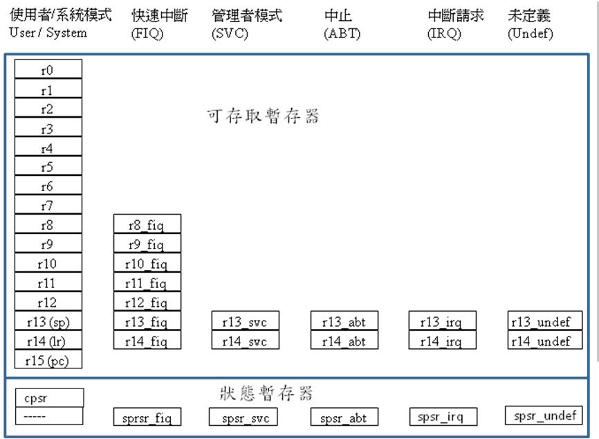
圖二、ARM 各種模式下的暫存器
當快速中斷發生時,ARM 處理器會自動將狀態暫存器 CPSR 放入 SPSR_fiq,並將R15(PC) 放入 R14_fiq(LR) 中,這有點像副程式呼叫時的作法。另外,由於快速中斷模式中,R8_fiq-R14_fiq 被用來取代 R8-R14,這使得 R8_fiq-R14_fiq這七個暫存器可以直接被寫入,而不需要特別保存,有利於縮短快速中斷的時間。圖三顯示了 ARM 的快速中斷機制之原理。

圖三、ARM 的快速中斷機制
ARM 的狀態暫存器 (CPSR, SPSR)
狀態暫存器 CPSR 與 SPSR的結構如圖四所示,除了用來儲存條件旗標之外,還有中斷控制位元 I、F,可用來允許或禁止中斷,狀態位元 T 用來記錄處理器是位於正常 (ARM:指令為32位元) 或精簡 (Thumb:指令為16位元) 狀態,處理器模式 Mode 是用來記錄處理器的模式,像是 (User / System / FIQ / SVC / ABT / IRQ / Undef) 等。

圖四、ARM 的狀態暫存器結構
ARM 的指令格式
ARM的指令格式如圖五所示,其中,位於31-28 位元的 Cond 欄位,是指令前置條件欄,因此每個 ARM 指令都是條件式執行的,這使得 ARM 不需要有像 CPU0 一樣多的條件跳躍指令 (像是 JEQ、JNE、JGT、JGE、JLT、JLE 等)。因此,ARM 的跳躍類指令只有 B、BL、BX 等三個,其中 BL 是會儲存程式計數器 PC到 LR 當中的跳躍,通常用來進行副程式的呼叫,而 BX 則是會儲存狀態暫存器的跳躍。

圖五、ARM 指令的一般格式
ARM的指令集
表格一顯示了ARM處理器的指令表,包含運算、記憶體、分支與其他等四類,另外,若有協同處理器時,會有第五類指令可用。由於本書篇幅的關係,在此不對指令進行詳細介紹,有興趣的讀者請進一步參考 ARM 的相關書籍 。
表格一、ARM 的指令集
| 指令 | 說明 | 意義 |
| 運算指令 | ||
| MOV {cond}{S} Rd,operand2 | 資料傳送 | Rd<=operand2 |
| MVN{cond}{S} Rd,operand2 | 負資料傳送 | Rd<=(~operand2) |
| ADD{cond}{S} Rd,Rn,operand2 | 加法運算 | Rd<=Rn+operand2 |
| SUB{cond}{S} Rd,Rn,operand2 | 減法運算 | Rd<=Rn-operand2 |
| RSB{cond}{S} Rd,Rn,operand2 | 逆向減法 | Rd<=operand2-Rn |
| ADC{cond}{S} Rd,Rn,operand2 | 帶進位加法 | Rd<=Rn+operand2+Carry |
| SBC{cond}{S} Rd,Rn,operand2 | 帶進位減法 | Rd<=Rn-operand2-(NOT)Carry |
| RSC{cond}{S} Rc,Rn,operand2 | 帶進位逆向減法 | Rd<=operand2-Rn-(NOT)Carry |
| AND{cond}{S} Rd,Rn,operand2 | 邏輯“與”操作 | Rd<=Rn&operand2 |
| ORR{cond}{S} Rd,Rn,operand2 | 邏輯“或”操作 | Rd<=Rn|operand2 |
| EOR{cond}{S} Rd,Rn,operand2 | 邏輯“互斥或” | Rd<=Rn^operand2 |
| BIC{cond}{S} Rd,Rn,operand2 | 位元清除 | Rd<=Rn&(~operand2) |
| CMP{cond} Rn,operand2 | 比較指令 | 標誌 N、Z、C、V<=Rn-operand2 |
| CMN{cond} Rn,operand2 | 負數比較指令 | 標誌 N、Z、C、V<=Rn+operand2 |
| TST{cond} Rn,operand2 | 位元測試指令 | 標誌 N、Z、C、V<=Rn&operand2 |
| TEQ{cond} Rn,operand2 | 相等測試指令 | 標誌 N、Z、C、V<=Rn^operand2 |
| 記憶體相關指令 | ||
| LDR{cond} Rd,addressing | 載入 Word | Rd<=[addressing] |
| LDR{cond}B Rd,addressing | 載入 Byte | Rd<=[addressing] |
| LDR{cond}T Rd,addressing | 載入Word (以使用者模式) | Rd<=[addressing] |
| LDR{cond}BT Rd,addressing | 載入Byte (以使用者模式) | Rd<=[addressing] |
| LDR{cond}H Rd,addressing | 載入半字組 | Rd<=[addressing] |
| LDR{cond}SB Rd,addressing | 載入 byte (有正負號) | Rd<=[addressing] |
| LDR{cond}SH Rd,addressing | 載入半字組 (有正負號) | Rd<=[addressing] |
| STR{cond} Rd,addressing | 儲存Word | [addressing]<=Rd |
| STRB{cond} Rd,addressing | 儲存Byte | [addressing]<=Rd |
| STR{cond}T Rd,addressing | 儲存Word (以使用者模式) | [addressing]<=Rd |
| STR{cond}BT Rd,addressing | 儲存byte (以使用者模式) | [addressing]<=Rd |
| STR{cond}H Rd,addressing | 儲存半字組 | [addressing]<=Rd |
| LDM{cond}{mode} Rn{!},reglist | 多暫存器載入 | reglist<=[Rn…],Rn 寫回 |
| STM{cond}{mode} Rn{!},reglist | 多暫存器儲存 | [Rn…]<=reglist, Rn 寫回 |
| SWP{cond} Rd,Rm,Rn | 暫存器和記憶體字資料交換指令 | Rd<=[Rn],[Rn]<=Rm (Rn≠Rd或Rm) |
| SWP{cond}B Rd,Rm,Rn | 暫存器和記憶體位元組資料交換指令 | Rd<=[Rn],[Rn]<=Rm (Rn≠Rd或Rm) |
| 分支指令 | ||
| B{cond} label | 分支指令 | PC<=label |
| BL{cond} label | 帶連接的分支 | LR<=PC-4,PClabel |
| BX{cond} label | 帶狀態的分支 | PC<=label, 切換處理器狀態 |
| 其他指令 | ||
| SWI{cond} immed_24 | 軟中斷指令 | 產生軟中斷,處理器進入管理模式 |
| MRS{cond} Rd,psr | 讀狀態暫存器指令 | Rd<=psr,psr為 CPSR 或 SPSR |
| MSR{cond} psr_fields,Rd/#immend_8r | 寫狀態暫存器指令 | psr_fields<=Rd/#immed_8r,p 為 CPSR 或 SPSR |
| 協同處理器指令 | ||
| CDP{cond} coproc,opcode1,CRd,CRn,CRm(,opcode2) | 協同處理器資料操作指令 | 取決於協同處理器 |
| LDC{cond}{L} coproc,CRd,<地址> | 協同處理器資料讀取指令 | 取決於協同處理器 |
| STC{cond}{L} coproc,CRd,<地址> | 協同處理器資料寫入指令 | 取決於協同處理器 |
| MCR{cond} coproc,opcodel,Rd,CRn,CRm{,opcode2} | ARM暫存器到協同處理器暫存器的資料傳送指令 | 取決於協同處理器 |
| MRC{cond} coproc,opcodel,Rd,CRn,CRm{,opcode2} | 協同處理器暫存器到ARM暫存器的資料傳送指令 | 取決於協同處理器 |
Come from wiki:
The Status register
While the ARM has always been a 32 bit processor, the original design had the Program Counter and Processor Status Register both sharing R15. For this reason, older processors are often referred to as "being 26 bit". This refers to the width of the Program Counter.
A Program Counter of 26 bits allows addressing only within a 64MiB range, so this really only pertains to older RISC OS computers (which typically offered 4MiB or sometimes 8MiB onboard). Contemporary ARM processors offer a full 32 bit Program Counter allowing access to up to 4Gb of directly addressable memory, along with separate status registers.
Contents[hide] |
Contemporary processors
There is a Current Processor Status Register (CPSR) which is the same across all processor modes. Then there is the Saved Processor Status Register (SPSR) which is specific to each mode, with the exception of User mode and System mode (the two least privileged modes) which do not have a SPSR.
Bit allocation
The allocation of the bits within the CPSR (and SPSR) is:
| 31 | 30 | 29 | 28 | 27 | 24 | 19 … 16 | 9 | 8 | 7 | 6 | 5 | 4 … 0 | |||
| N | Z | C | V | Q | — | J | — | GE[3:0] | — | E | A | I | F | T | M[4:0] |
The Condition flags are as follows:
- Negative: is set to bit 31 of the result, so N is 1 if the signed value is negative, and cleared if the result is positive or zero.
- Zero: is set if the result is zero; this is usual to denote an equal result from a comparison. If the result is non-zero, this flag is cleared.
- Carry: Is more complex:
- With the instructions ADC, ADD, and CMN, this flag is set if the result would produce an unsigned overflow.
- With the instructions CMP, SBC, and SUB, this flag is set if the result would produce an unsigned underflow (a borrow).
- For other instructions that use shifting, this flag is set to the value of the last bit shifted out by the shifter.
- Other instructions usually leave this flag alone.
- oVerflow: for addition and subtraction, this flag is set if a signed overflow occurred. Otherwise, it is generally left alone. Note that some API conventions may specifically set oVerflow to flag an error condition.
The Interrupt flags are as follows:
- I: when set, disables IRQ interrupts
- F: when set, disables FIQ interrupts
- A: [ARMv6 and later] when set, disables imprecise aborts (this is an abort on a memory write that has been held in a write buffer in the processor and not written to memory until later, perhaps after another abort or interrupt is in progress.
The Instruction set flags are as follows:
- Thumb
- Jazelle
These are set in the following pattern:
| J | T | Instruction set |
|---|---|---|
| 0 | 0 | ARM (standard) |
| 0 | 1 | Thumb |
| 1 | 0 | Jazelle |
| 1 | 1 | Reserved |
The T bit exists on Thumb capable processors (ARMv4 and later, according to capabilities), the J bit exists on Jazelle capable processors (ARMv5 and later, according to capabilities). Both J and T bits exist in the ARMv6 processors.
The other bits are as follows:
- Q: this flag is set in E variants of of ARMv5 and above to indicate underflow and/or saturation is used in instructions intended to assist DSP operations.
- GE[3:0]: these flags, in ARMv6, control the Greater than or Equal behaviour in SIMD instructions. For halfword instructions, if bits 3:2 are set, the upper halfword is used; and if bits 1:0 are set, the lower halfword is set. Similarly, for byte opeations, if bit 3 is set, the top byte is used; if bit 0 is set, the bottom byte is used; and bits/bytes 2 and 1 in the same fashion.
- E: is a flag in ARMv6 that controls the 'endianness' for data handling. Instruction fetches are unchanged, little-endian and word aligned (halfword for Thumb).
In little-endian formats, the first byte at a word-aligned address is the least significant byte. Thus, the hex value 0xDEADBEEF would appear as EF, BE, AD, DE; while big-endian formats would have the first byte as the most significant, leading to the memory holding DE, AD, BE, EF.
Actually setting up endian support requires co-operation between the status register and flags in the CP15 processor configuration, and is therefore beyond the scope of this document.
Processor mode bits are as follows:
| M[4:0] | Mode | Register Set |
|---|---|---|
| %10000 | User | R0-R14, CPSR, PC |
| %10001 | FIQ | R0-R7, R8_fix-R14_fiq, CPSR, SPSR_fiq, PC |
| %10010 | IRQ | R0-R12, R13_irq, R14_irq, CPSR, SPSR_irq, PC |
| %10011 | SVC (supervisor) | R0-R12, R13_svc R14_svc CPSR, SPSR_irq, PC |
| %10111 | Abort | R0-R12, R13_abt R14_abt CPSR, SPSR_abt PC |
| %11011 | Undefined | R0-R12, R13_und R14_und, CPSR, SPSR_und PC |
| %11111 | System (ARMv4+) | R0-R14, CPSR, PC |
Older processors, namely the ARM6, ARM7, and StrongARM (plus related devices, such as the ARM7500FE) offered legacy support for the 26 bit mode, as was used by RISC OS at the time.
The processor mode choices thus were as above, but also included the following:

It is also possible, in this configuration, to select 26 bit modes by using the older PC+PSR method.
The Processor Modes and their use/behaviour are defined separately.
Manipulating the PSR
To copy a register into the PSR:
  MSR     CPSR, R0                ; Copy R0 into CPSR
  MSR     SPSR, R0                ; Copy R0 into SPSR
  MSR     CPSR_flg, R0            ; Copy flag bits of R0 into CPSR
  MSR     CPSR_flg, #1<<28        ; Copy flag bits (immediate) into CPSR
To copy the PSR into a register:
 MRS     R0, CPSR                ; Copy CPSR into R0
 MRS     R0, SPSR                ; Copy SPSR into R0
You have two PSRs - the CPSR which is the Current Program Status Register and SPSR which is the Saved Program Status Register (the previous processor mode's PSR). Each privileged mode has its own PSR, so the total available selection of PSR is:
- CPSR_all - current
- CPSR_flg - current, flags only
- SPSR - saved, current
- SPSR_svc - saved, SVC(32) mode
- SPSR_irq - saved, IRQ(32) mode
- SPSR_abt - saved, ABT(32) mode
- SPSR_und - saved, UND(32) mode
- SPSR_fiq - saved, FIQ(32) mode
You can only alter the SPSR of the mode you are currently in, thus if you are in SVC mode, you cannot MRS to update SPSR_fiq. The way to do this, should it be necessary, is to temporarily enter the mode relating to the SPSR you wish to update it, and do it that way. Using the _flg suffix allows you to alter the flag bits without affecting the control bits.
In User(32) mode, the control bits of CPSR are protected, you can only alter the condition flags. In other modes, the entire CPSR is available. You should not specify R15 as a source or destination register. And finally, you must not attempt to access the SPSR in User(32) mode as it doesn't exist!
To set the V flag without affecting the control bits:
MSR CPSR_flg, #&10000000
Alternatively, here is a clever way to set the V flag on any ARM processor:
  CMP     R0, #1<<31
  CMNVC   R0, #1<<31
To change mode:
 MRS     R0, CPSR_all            ; Copy the PSR
 BIC     R0, R0, #&1F            ; Clear the mode bits
 ORR     R0, R0, #new_mode       ; Set bits for new mode
 MSR     CPSR_all, R0            ; write PSR back, changing mode
- Important: Your assembler may complain that "CPSR_all" is not recognised, or that you need some weird syntax such as "CPSR_nvf"; please refer to the documentation supplied with your assembler to figure out exactly what its MSR/MRS syntax is...
Transitioning to 32 bit mode
For old time RISC OS coders, here's a quick résumé of things to avoid when writing 32 bit code:
- Never use
MOVS PC, Rxx - Never use
LDMFD R13!, {Rxx-Rxx, PC}^ - Specify your routines as corrupting processor flags, and make no attempt to preserve them, let the caller do that
- Don't assume anything else preserves the processor flags - do it yourself before calling functions that could corrupt flags
Things are a little more complicated with APCS, but since the new C compiler can make code that runs on older machines as well as the newer ones (Iyonix, BeagleBoard, etc); why not convert your projects to be 26/32 neutral? This seems like the easiest way; though all that is really required in assembler is:
  [ {CONFIG=26}
    ; 26bit return
    MOVS    PC, R14     ; or LDMFD xxxx^
  |
    ; 32bit return
    MOV     PC, R14     ; or LDMFD xxxx
  ]
objasm will then sort out which code to use depending on whether it is assembling for 26 bit or 32 bit...
Legacy processors (26 bit)
26 bit mode is a mostly obsolete method that is used in the original RISC OS machines and all versions of RISC OS from RISC OS 2 to RISC OS 4 (Select/Adjust) inclusive.
Specifically, the ARM2, ARM250, and ARM3 support only this mode of operation. The ARM6(10), ARM7(10), ARM7500(FE), and StrongARM support dual 26/32 operation for use with original versions of RISC OS.
- The 'open' version of RISC OS is 32 bit compliant. https://www.riscosopen.org/content/
R15: PC+PSR
In the original mode, the Status Register and Program Counter were combined in a single register, as follows:
As the Program Counter was only expected to address 64MiB, it only needed to be 26 bits wide, the upper six bits being the four flags (NZCV) and the IRQ/FIQ disable bits. Furthermore, as every address is word aligned, the bottom two bits of the address would always be zero, so they could be used for a different purpose in the PC+PSR arrangement. Specifically, these bits held the current Processor Mode as follows:

When R15 is used as the first operand in an instruction, only the Program Counter part of it is available. Thus, the following instruction will copy PC out to a register and add 256 to it:
ADD R0, R15, #256
When R15 is used as the second operand, all 32 bits are accessible: the Program Counter, the flags, and the status. The following code segment will identify the current processor mode:
   MOV     R0, #3          ; Load a bit mask (%11) into R0
   AND     R0, R0, PC      ; AND R15 into R0, to get the mode status
   CMP     R0, #3          ; Compare mode with '3' (SVC)
   BEQ     svc             ; If SVC mode, branch to 'svc'
   CMP     R0, #2          ; Compare mode with '2' (IRQ)
   BEQ     irq             ; If IRQ mode, branch to 'irq'
   CMP     R0, #1          ; Compare mode with '1' (FIQ)
   BEQ     fiq             ; If FIQ mode, branch to 'fiq'
   CMP     R0, #0          ; Compare mode with '0' (USR)
   BEQ     usr             ; If USR mode, branch to 'usr'
   ; This is just an example, for it might be better to
   ; fall-through for the final case instead of branching.
You might ask why it wouldn't be possible to do AND R0, PC, #3 to save an instruction. This won't work as when PC is the first operand, only the PC part is visible. It must be the final operand in order to have the mode and flags visible.
Changing processor status
In order to change the processor mode, or indeed any of the flags, we need to EOR the desired flag with the status flags. There is pseudocode for changing the changing the state of the oVerflow flag:
new_state = old_state EOR (1 << 28)
But we cannot do a simple EORS operation as writing back to R15 would affect the pipeline and cause the following two instructions to be skipped.
But don't worry. The instruction TEQ does a pretend EOR (the results are not stored anywhere, we don't need them). Combine this with the P suffix, which writes bits 0, 1, and 26 to 31 of the result directly to bits 0, 1, and 26 to 31 of R15 giving you an easy way to change the flags:
TEQP R15, bit_mask
You can only change a flag if you are in a processor mode which allows you to set that flag, namely you cannot sit in USR mode and instruct the processor to enter SVC mode.
  MOV     R6, PC          ; Store original state of PC in R6
  ORR     R7, R6, #3      ; Set SVC mode
  TEQP    R7, #0          ; Write mode flags (in R7) to PC
And to return to the original mode:
TEQP R6, #0 ; Write previous mode flags (in R6) back to PC
After changing the mode, you should perform a null operation to allow the registers to settle. The standard NOP is MOV R0, R0.


 4844
4844

 被折叠的 条评论
为什么被折叠?
被折叠的 条评论
为什么被折叠?
 到【灌水乐园】发言


