


7.1 A 4- to 20 -mA control signal is loaded by a resistor and must produce a 20- to 40-V motor drive signal. Find an equation relating the input current to the output voltage.
Soluting:
7.5 Modify Problem 7.4 by using a DIAC with a breakover voltage, in place of the
resistor, to trigger a TRIAC. The source is now a bipolar
square wave of the same period as Figure 7.49 .

a. Find the range of R to provide a 5 % to 95 % on time.
Now the system has the form:

The values of with
5 % on-time:
95 % on-time:
b. Plot the voltages across the capacitor, load, and TRIAC.

c. What is the average power delivered to the load?
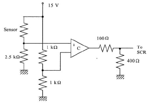
7.7 Figure 7.50 shows a system to regulate dc motor speed by temperature. A thermistor is used to vary the capacitor charging rate, and thus when in the cycle the SCR is turned on. The thermistor resistance versus temperature is given in Figure 4.5 .


a. Determine the values for the resistor and capacitor to provide 10 % on time at and 90 % on time at
.
The SCR will fire when =1.5V
,
So .
b. Determine the required power ratings of the zener diode and resistor.
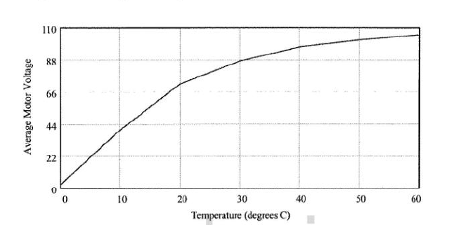
c. Construct a plot of the average motor voltage versus temperature.
Through Figure 4.5, we can obtain the resistance at the corresponding temperature and obtain the temperature voltage curve.
7.11 A stepping motor has per step. Find the rpm produced by a pulse rate of 2000 pps on the input.
The motor steps once for each pulse, so,
There are per revolution, so,
There are 60 seconds per minute, so,
7.15 The SCR in Figure 7.26 requires a 4-V trigger. Design a system by which the gears are shifted when a CdS photocell resistance drops below .

We can use a comparator to solve this problem . This comparator is assumed to have a 5 volt high output so this is divided to obtain the required 4 volt SCR trigger. A simple divider provides the 7.5 volt comparator trigger voltage. As the light intensity increases the photocell resistance will drop, which increases . When the cell reaches
,
will rise to 7.5 volts and the comparator will go high.
7.20 The level of water in a tank is to be controlled at , and the output flow rate is nominally
through a control valve, as shown in Figure 7.51 . Under nominal conditions, determine the required valve size in inches and centimeters.

We will use the relation,
The pressure is simply the gauge pressure at the outlet,
From Table 7.1 this requires a 2 inch or 5 \mathrm{~cm} valve,
7.21 If the valve actuator of Problem 7.20 has a rangeability of 30 and a maximum stem travel of and is to be half-open under the nominal conditions, find the minimum flow, maximum flow, and stem opening for
flow.
When the stem is half open,
, so
The maximum flow is found as,
For ,


 655
655


 被折叠的 条评论
为什么被折叠?
被折叠的 条评论
为什么被折叠?
 到【灌水乐园】发言


