


 本文详细介绍了通信的基本概念,包括串行通信、并行通信、异步通信和同步通信的原理。串行通信通过一条数据线依次传输数据,适合远距离通信;并行通信则同时传输多位数据,传输速度快但不适合长距离。异步通信允许发送和接收设备使用各自的时钟,字符间有间隔,适合简单系统;同步通信则要求设备完全同步,传输效率高。此外,还讲解了单工、半双工和全双工通信的区别。以F28335处理器为例,展示了SCI接口的配置、发送和接收函数,以及如何与RS-232接口配合使用。
1.通信的基本概念
通信的方式可以分为多种,按照数据传送方式可分为串行通信和并行通信。按照通信的数据同步方式,可分为异同通信和同步通信。按照数据的传输方向又可分为单工、半双工和全双工通信。下面我们就来简单介绍这几种通信方式。
1.1 串行通信与并行通信
(1)串行通信
串行通信是指使用一条数据线,将数据一位一位地依次传输,每一位数据占据一个固定的时间长度。其只需要少数几条线就可以在系统间交换信息,特别适用于计算机与计算机、计算机与外设之间的远距离通信。
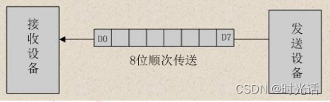
串行通信的特点:传输线少,长距离传送时成本低,且可以利用电话网等现成的设备,但数据的传送控制比并行通信复杂。
(2)并行通信
并行通信通常是将数据字节的各位用多条数据线同时进行传送,通常是8位、16位、32位等数据一起传输。
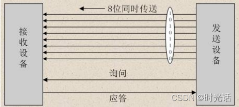
并行通信的特点:控制简单、传输速度快;由于传输线较多,长距离传送时成本高且接收方的各位同时接收存在困难,抗干扰能力差 。
1.2 异步通信与同步通信
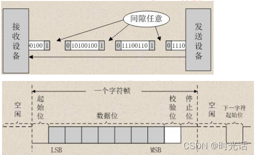
(1)异步通信
异步通信是指通信的发送与接收设备使用各自的时钟控制数据的发送和接收过程。为使双方的收发协调,要求发送和接收设备的时钟尽可能一致。
异步通信是以字符(构成的帧)为单位进行传输,字符与字符之间的间隙(时间间隔)是任意的,但每个字符中的各位是以固定的时间传送的,即字符之间不一定有“位间隔”的整数倍的关系,但同一字符内的各位之间的距离均为“位间隔”的整数倍。
异步通信的特点:不要求收发双方时钟的严格一致,实现容易,设备开销较小,但每个字符要附加2~3位用于起止位,各帧之间还有间隔,因此传输效率不高 。
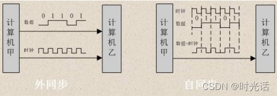
(2)同步通信
同步通信时要建立发送方时钟对接收方时钟的直接控制,使双方达到完全同步。此时,传输数据的位之间的距离均为“位间隔”的整数倍,同时传送的字符间不留间隙,即保持位同步关系,也保持字符同步关系。发送方对接收方的同步可以通过两种方法实现。
1.3 单工、半双工与全双工通信
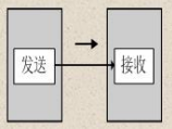
(1)单工通信
单工是指数据传输仅能沿一个方向,不能实现反向传输。
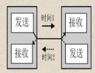
(2)半双工通信
半双工是指数据传输可以沿两个方向,但需要分时进行。
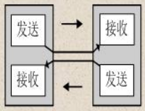
(3)全双工通信
全双工是指数据可以同时进行双向传输。
1.4 通信速率
衡量通信性能的一个非常重要的参数就是通信速率,通常以比特率(Bitrate)来表示。比特率是每秒钟传输二进制代码的位数,单位是:位/秒(bps)。如每秒钟传送240个字符,而每个字符格式包含10位(1个起始位、1个停止位、8个数据位),这时的比特率为:
10位×240个/秒 = 2400 bps
2.F28335的SCI介绍
2.1 串口通信简介
串口通信(Serial Communication),是指外设和计算机间,通过数据信号线、地线等,按位进行传输数据的一种通信方式,属于串行通信方式。串口是一种接口标准,它规定了接口的电气标准,没有规定接口插件电缆以及使用的协议。
(1)接口标准
串口通信的接口标准有很多,有RS-232C、RS-232、RS-422A、RS-485等。常用的就是RS-232和RS-485。RS-232其实是RS-232C的改进,原理是一样的。这里我们就以RS-232C接口进行讲解,RS-485在后面章节中会介绍。
RS-232C是EIA(美国电子工业协会)1969年修订RS-232C标准。RS-232C定义了数据终端设备(DTE)与数据通信设备(DCE)之间的物理接口标准。
RS-232C接口规定使用25针连接器,简称DB25,连接器的尺寸及每个插针的排列位置都有明确的定义 。
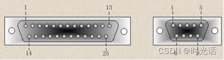
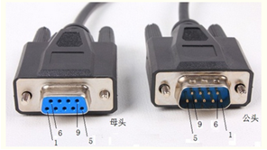
公头和母头的管脚定义顺序是不一样,这一点需要特别注意。常用管脚的功能如下:
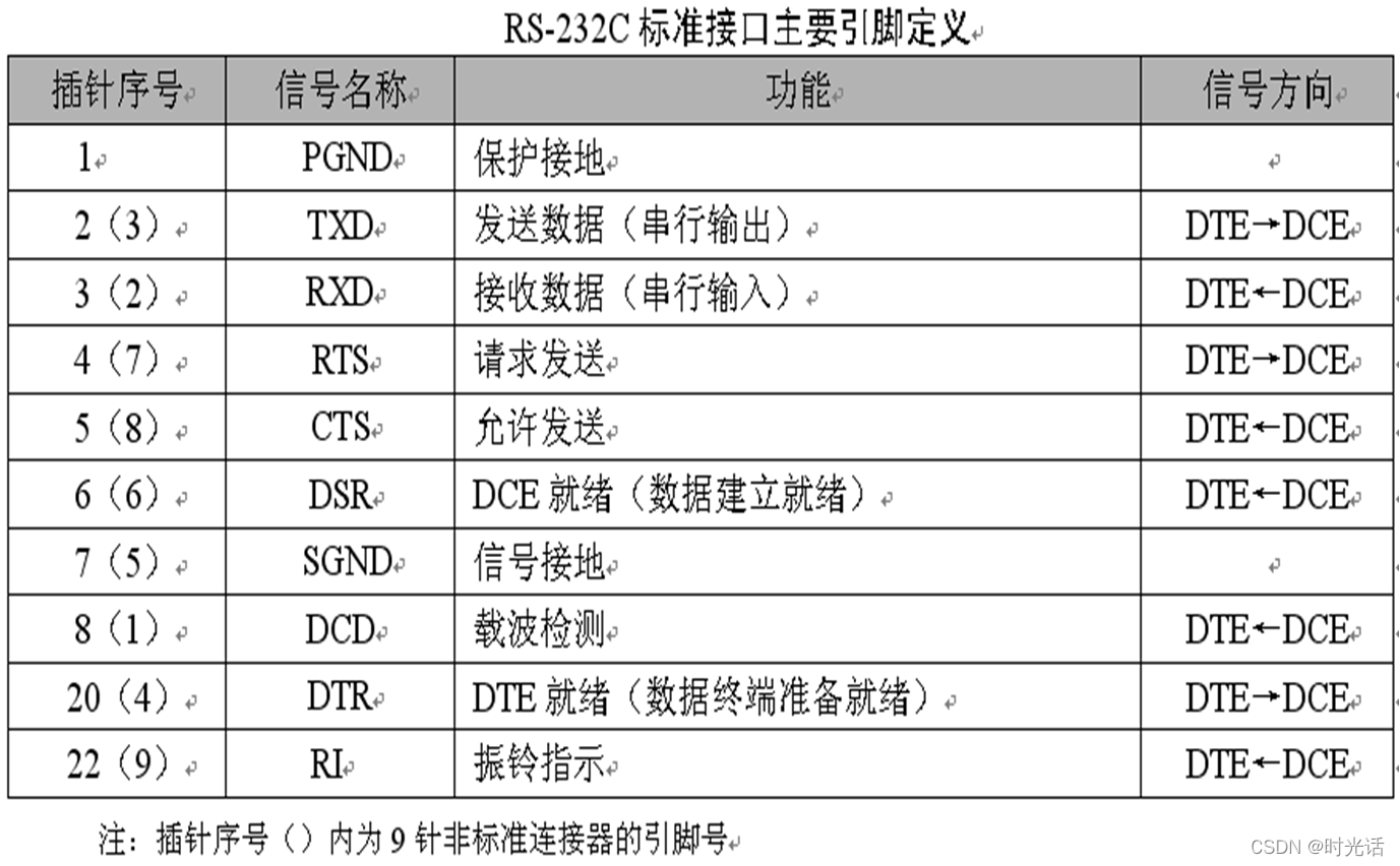
RS-232C对逻辑电平也做了规定,如下
在TXD和RXD数据线上:
1.逻辑1为-3~-15V的电压
2.逻辑0为3~15V的电压
在RTS、CTS、DSR、DTR和DCD等控制线上:
1.信号有效(ON状态)为3~15V的电压
2.信号无效(OFF状态)为-3~-15V的电压
由此可见,RS-232C是用正负电压来表示逻辑状态,与晶体管-晶体管逻辑集成电路(TTL)以高低电平表示逻辑状态的规定正好相反。
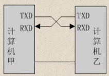
串口通信中还需要注意的是,串口数据收发线要交叉连接,计算机的TXD要对应单片机的RXD,计算机的RXD要对应单片机的TXD,并且共GND,如下图:
(2)通信协议
RS232的通信协议比较简单,通常遵循96-N-8-1格式。
2.2 SCI 简介
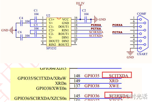
SCI(Serial Communication Interface)串行通信接口,接收和发送有各自独立的信号线,但不是同一个时钟,所以是进行串行异步通信接口,一般可以看作是 UART(通用异步收发器),经常和 RS232 接口连接。通常 DSP 引脚输入/输出使用 TTL 电平,而 TTL 电平的 1 和 0 的特征电压分别是 2.4V 和 0.4V,适用于板内数据传输。TTL 电平与 RS232 电平之间要互相转换,常使用 MAX232 进行转换。
F28335 处理器共有 3 个 SCI 接口,相对 TI 的 C240X 系列 DSP 的 SCI 接口,功能上有很大的改进,在原有功能基础上增加了通信速率自动检测和 FIFO 缓冲等新功能,为了减小串口通信时 CPU 的开销,F28335 的串口支持 16 级接收和发送 FIFO。
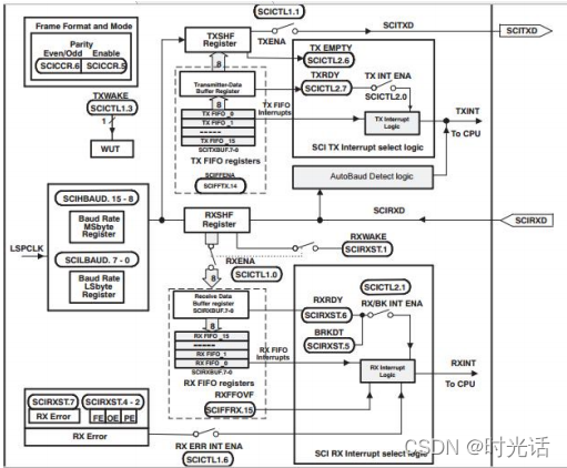
2.3 SCI 结构框图
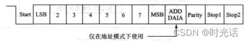
(1)SCI 数据格式
SCI 的发送和接收都采用不归零码格式,具体包括:
①1 位起始位
②1~8 位数据。
③1 个奇偶校验位(可选择)。
④1 位或 2 位停止位。
⑤区分数据和地址的附加位(仅在地址位模式存在)
数据的基本单元称为字符,它有 1~8 位长。每个字符包括 1 位启动位、1 或2 位停止位、可选择的奇偶校验位和地址位。在 SCI 通信中,带有格式信息的数字字符称为帧,如下图所示:
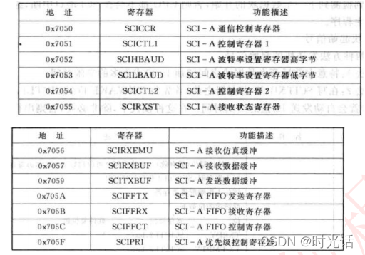
2.4 SCI 相关寄存器
3.SCI配置步骤
SCI 相关库函数在 DSP2833x_Sci.c和 DSP2833x_Sci.h 文件中
(1)使能 SCI 外设时钟及初始化对应 GPIO
EALLOW;
SysCtrlRegs.PCLKCR0.bit.SCIAENCLK = 1; // SCI-A
EDIS;

InitSciGpio();
(2)SCI 工作方式及参数设置,包括数据格式、波特率、使能发送、接收功能等。
//Initalize the SCI FIFO
SciaRegs.SCIFFTX.all=0xE040;
SciaRegs.SCIFFRX.all=0x204f;
SciaRegs.SCIFFCT.all=0x0;

// Note: Clocks were turned on to the SCIA peripheral
// in the InitSysCtrl() function
SciaRegs.SCICCR.all =0x0007; // 1 stop bit, No loopback

// No parity,8 char bits,
// async mode, idle-line protocol
SciaRegs.SCICTL1.all =0x0003; // enable TX, RX, internal SCICLK,

// Disable RX ERR, SLEEP, TXWAKE
SciaRegs.SCICTL2.all =0x0003;
SciaRegs.SCICTL2.bit.TXINTENA =1;
SciaRegs.SCICTL2.bit.RXBKINTENA =1;
SciaRegs.SCIHBAUD =scihbaud; // baud set @LSPCLK = 37.5MHz.
SciaRegs.SCILBAUD =scilbaud;

// SciaRegs.SCICCR.bit.LOOPBKENA =1; // Enable loop back
SciaRegs.SCICTL1.all =0x0023; // Relinquish SCI from Reset
scibaud=37500000/(8*baud)-1;
scihbaud=scibaud>>8;
scilbaud=scibaud&0xff;
(3)SCI 发送字节函数
void UARTa_SendByte(int a)
{
   while (SciaRegs.SCIFFTX.bit.TXFFST != 0);
   SciaRegs.SCITXBUF=a;
}

void UARTa_SendString(char * msg)
{
    int i=0;

    while(msg[i] != '\0')
    {
        UARTa_SendByte(msg[i]);
        i++;
    }
}
(4)SCI 接收字节函数
// Wait for inc character
while(SciaRegs.SCIFFRX.bit.RXFFST !=1);// wait for XRDY =1 for empty state
// Get character
ReceivedChar = SciaRegs.SCIRXBUF.all;
4.硬件设计
本实验使用到硬件资源如下:
(1)D1 指示灯
(2)SCIA
(3)RS232 模块
5.软件设计
本章所要实现的功能是:通过 SCIA 实现与 PC 机对话,F28335 的 SCIA 收到 PC 机发来的数据后原封不动的返回给 PC 机显示,定时器 0 控制 D1 指示灯闪烁,提示系统运行状态。程序框架如下:
(1)初始化 SCIA 相关参数,开启串口发送和接收功能
(2)编写串口发送函数
(3)编写主函数
(1)SCI_loopback
void InitSciaGpio()
{
   EALLOW;

/* Enable internal pull-up for the selected pins */
// Pull-ups can be enabled or disabled disabled by the user.
// This will enable the pullups for the specified pins.

	GpioCtrlRegs.GPBPUD.bit.GPIO36 = 0;    // Enable pull-up for GPIO36 (SCIRXDA)
	GpioCtrlRegs.GPBPUD.bit.GPIO35 = 0;	   // Enable pull-up for GPIO35 (SCITXDA)

/* Set qualification for selected pins to asynch only */
// Inputs are synchronized to SYSCLKOUT by default.
// This will select asynch (no qualification) for the selected pins.

	GpioCtrlRegs.GPBQSEL1.bit.GPIO36 = 3;  // Asynch input GPIO28 (SCIRXDA)

/* Configure SCI-A pins using GPIO regs*/
// This specifies which of the possible GPIO pins will be SCI functional pins.

	GpioCtrlRegs.GPBMUX1.bit.GPIO36 = 1;   // Configure GPIO36 for SCIRXDA operation
	GpioCtrlRegs.GPBMUX1.bit.GPIO35 = 1;   // Configure GPIO35 for SCITXDA operation

    EDIS;
}

void UARTa_Init(Uint32 baud)
{
	EALLOW;
	SysCtrlRegs.PCLKCR0.bit.SCIAENCLK = 1;   // SCI-A
	EDIS;

	InitSciaGpio();

	//Initalize the SCI FIFO
	SciaRegs.SCIFFTX.all=0xE040;
	SciaRegs.SCIFFRX.all=0x204f;
	SciaRegs.SCIFFCT.all=0x0;

	// Note: Clocks were turned on to the SCIA peripheral
	// in the InitSysCtrl() function
	SciaRegs.SCICCR.all =0x0007;   // 1 stop bit,  No loopback
								   // No parity,8 char bits,
								   // async mode, idle-line protocol
	SciaRegs.SCICTL1.all =0x0003;  // enable TX, RX, internal SCICLK,
								   // Disable RX ERR, SLEEP, TXWAKE
	SciaRegs.SCICTL2.all =0x0003;
	SciaRegs.SCICTL2.bit.TXINTENA =1;
	SciaRegs.SCICTL2.bit.RXBKINTENA =1;
	SciaRegs.SCIHBAUD    =0x0000;
	SciaRegs.SCILBAUD    =0x000F;
	SciaRegs.SCICCR.bit.LOOPBKENA =1; // Enable loop back
	SciaRegs.SCICTL1.all =0x0023;     // Relinquish SCI from Reset
}

// Transmit a character from the SCI'
void UARTa_SendByte(int a)
{
    SciaRegs.SCITXBUF=a;
    while(SciaRegs.SCIFFRX.bit.RXFFST !=1); // wait for XRDY =1 for empty state
}

void main()
{
	int i=0;
	Uint16 SendChar=0;
	Uint16 ReceivedChar=0;

	InitSysCtrl();
	InitPieCtrl();
	IER = 0x0000;
	IFR = 0x0000;
	InitPieVectTable();

	LED_Init();
	TIM0_Init(150,200000);//200ms
	UARTa_Init(9600);

	while(1)
	{
		UARTa_SendByte(SendChar);
		// Check received character
		ReceivedChar = SciaRegs.SCIRXBUF.all;
		if(ReceivedChar != SendChar)LED2_TOGGLE;
		DELAY_US(100*1000);

		// Move to the next character and repeat the test
		SendChar++;
		// Limit the character to 8-bits
		SendChar &= 0x00FF;
	}
}
(2)SCI_echoback
void UARTa_Init(Uint32 baud)
{
	unsigned char scihbaud=0;
	unsigned char scilbaud=0;
	Uint16 scibaud=0;

	scibaud=37500000/(8*baud)-1;
	scihbaud=scibaud>>8;
	scilbaud=scibaud&0xff;

	EALLOW;
	SysCtrlRegs.PCLKCR0.bit.SCIAENCLK = 1;   // SCI-A
	EDIS;

	InitSciaGpio();

	//Initalize the SCI FIFO
	SciaRegs.SCIFFTX.all=0xE040;
	SciaRegs.SCIFFRX.all=0x204f;
	SciaRegs.SCIFFCT.all=0x0;

	// Note: Clocks were turned on to the SCIA peripheral
	// in the InitSysCtrl() function
	SciaRegs.SCICCR.all =0x0007;   // 1 stop bit,  No loopback
								   // No parity,8 char bits,
								   // async mode, idle-line protocol
	SciaRegs.SCICTL1.all =0x0003;  // enable TX, RX, internal SCICLK,
								   // Disable RX ERR, SLEEP, TXWAKE
	SciaRegs.SCICTL2.all =0x0003;
	SciaRegs.SCICTL2.bit.TXINTENA =1;
	SciaRegs.SCICTL2.bit.RXBKINTENA =1;
	SciaRegs.SCIHBAUD    =scihbaud;  // 9600 baud @LSPCLK = 37.5MHz.
	SciaRegs.SCILBAUD    =scilbaud;
//	SciaRegs.SCICCR.bit.LOOPBKENA =1; // Enable loop back
	SciaRegs.SCICTL1.all =0x0023;     // Relinquish SCI from Reset

}

// Transmit a character from the SCI'
void UARTa_SendByte(int a)
{
	while (SciaRegs.SCIFFTX.bit.TXFFST != 0);
	SciaRegs.SCITXBUF=a;
}

void UARTa_SendString(char * msg)
{
	int i=0;

	while(msg[i] != '\0')
	{
		UARTa_SendByte(msg[i]);
		i++;
	}
}

void main()
{
	int i=0;
	char *msg;
	Uint16 ReceivedChar=0;

	InitSysCtrl();
	InitPieCtrl();
	IER = 0x0000;
	IFR = 0x0000;
	InitPieVectTable();

	LED_Init();
	TIM0_Init(150,200000);//200ms
	UARTa_Init(4800);

	msg = "Hello World!\r\n";
	UARTa_SendString(msg);
	msg = "You will enter a character, and the DSP will echo it back!\r\n";
	UARTa_SendString(msg);

	while(1)
	{
		msg = "\r\nEnter a character: ";
		UARTa_SendString(msg);

		// Wait for inc character
		while(SciaRegs.SCIFFRX.bit.RXFFST !=1);// wait for XRDY =1 for empty state
		// Get character
		ReceivedChar = SciaRegs.SCIRXBUF.all;

		// Echo character back
		msg = "  You sent: ";
		UARTa_SendString(msg);
		UARTa_SendByte(ReceivedChar);

		DELAY_US(1000);
	}
}
(3)SCI_autobaud
void UARTa_Init(Uint32 baud)
{
	unsigned char scihbaud=0;
	unsigned char scilbaud=0;
	Uint16 scibaud=0;

	scibaud=37500000/(8*baud)-1;
	scihbaud=scibaud>>8;
	scilbaud=scibaud&0xff;

	EALLOW;
	SysCtrlRegs.PCLKCR0.bit.SCIAENCLK = 1;   // SCI-A
	EDIS;

	InitSciaGpio();

	//Initalize the SCI FIFO
	SciaRegs.SCIFFTX.all=0xE040;
	SciaRegs.SCIFFRX.all=0x204f;
	SciaRegs.SCIFFCT.all=0x0;

	// Note: Clocks were turned on to the SCIA peripheral
	// in the InitSysCtrl() function
	SciaRegs.SCICCR.all =0x0007;   // 1 stop bit,  No loopback
								   // No parity,8 char bits,
								   // async mode, idle-line protocol
	SciaRegs.SCICTL1.all =0x0003;  // enable TX, RX, internal SCICLK,
								   // Disable RX ERR, SLEEP, TXWAKE
	SciaRegs.SCICTL2.all =0x0003;
	SciaRegs.SCICTL2.bit.TXINTENA =1;
	SciaRegs.SCICTL2.bit.RXBKINTENA =1;
	SciaRegs.SCIHBAUD    =scihbaud;  // 9600 baud @LSPCLK = 37.5MHz.
	SciaRegs.SCILBAUD    =scilbaud;
//	SciaRegs.SCICCR.bit.LOOPBKENA =1; // Enable loop back
	SciaRegs.SCICTL1.all =0x0023;     // Relinquish SCI from Reset
}

// Transmit a character from the SCI'
void UARTa_SendByte(int a)
{
	while (SciaRegs.SCIFFTX.bit.TXFFST != 0);
	SciaRegs.SCITXBUF=a;
}

void UARTa_SendString(char * msg)
{
	int i=0;

	while(msg[i] != '\0')
	{
		UARTa_SendByte(msg[i]);
		i++;
	}
}

void InitSciaGpio()
{
   EALLOW;

/* Enable internal pull-up for the selected pins */
// Pull-ups can be enabled or disabled disabled by the user.
// This will enable the pullups for the specified pins.

	GpioCtrlRegs.GPBPUD.bit.GPIO36 = 0;    // Enable pull-up for GPIO36 (SCIRXDA)
	GpioCtrlRegs.GPBPUD.bit.GPIO35 = 0;	   // Enable pull-up for GPIO35 (SCITXDA)

/* Set qualification for selected pins to asynch only */
// Inputs are synchronized to SYSCLKOUT by default.
// This will select asynch (no qualification) for the selected pins.

	GpioCtrlRegs.GPBQSEL1.bit.GPIO36 = 3;  // Asynch input GPIO28 (SCIRXDA)

/* Configure SCI-A pins using GPIO regs*/
// This specifies which of the possible GPIO pins will be SCI functional pins.

	GpioCtrlRegs.GPBMUX1.bit.GPIO36 = 1;   // Configure GPIO36 for SCIRXDA operation
	GpioCtrlRegs.GPBMUX1.bit.GPIO35 = 1;   // Configure GPIO35 for SCITXDA operation

    EDIS;
}

void InitScibGpio()
{
   EALLOW;

/* Enable internal pull-up for the selected pins */
// Pull-ups can be enabled or disabled disabled by the user.
// This will enable the pullups for the specified pins.
// Comment out other unwanted lines.

//  GpioCtrlRegs.GPAPUD.bit.GPIO9 = 0;     // Enable pull-up for GPIO9  (SCITXDB)
//  GpioCtrlRegs.GPAPUD.bit.GPIO14 = 0;    // Enable pull-up for GPIO14 (SCITXDB)
	GpioCtrlRegs.GPAPUD.bit.GPIO18 = 0;	   // Enable pull-up for GPIO18 (SCITXDB)
//  GpioCtrlRegs.GPAPUD.bit.GPIO22 = 0;    // Enable pull-up for GPIO22 (SCITXDB)


//  GpioCtrlRegs.GPAPUD.bit.GPIO11 = 0;    // Enable pull-up for GPIO11 (SCIRXDB)
//  GpioCtrlRegs.GPAPUD.bit.GPIO15 = 0;    // Enable pull-up for GPIO15 (SCIRXDB)
    GpioCtrlRegs.GPAPUD.bit.GPIO19 = 0;	   // Enable pull-up for GPIO19 (SCIRXDB)
//  GpioCtrlRegs.GPAPUD.bit.GPIO23 = 0;    // Enable pull-up for GPIO23 (SCIRXDB)

/* Set qualification for selected pins to asynch only */
// This will select asynch (no qualification) for the selected pins.
// Comment out other unwanted lines.

//  GpioCtrlRegs.GPAQSEL1.bit.GPIO11 = 3;  // Asynch input GPIO11 (SCIRXDB)
//  GpioCtrlRegs.GPAQSEL1.bit.GPIO15 = 3;  // Asynch input GPIO15 (SCIRXDB)
	GpioCtrlRegs.GPAQSEL2.bit.GPIO19 = 3;  // Asynch input GPIO19 (SCIRXDB)
//  GpioCtrlRegs.GPAQSEL2.bit.GPIO23 = 3;  // Asynch input GPIO23 (SCIRXDB)

/* Configure SCI-B pins using GPIO regs*/
// This specifies which of the possible GPIO pins will be SCI functional pins.
// Comment out other unwanted lines.

//  GpioCtrlRegs.GPAMUX1.bit.GPIO9 = 2;    // Configure GPIO9 for SCITXDB operation
//  GpioCtrlRegs.GPAMUX1.bit.GPIO14 = 2;   // Configure GPIO14 for SCITXDB operation
	GpioCtrlRegs.GPAMUX2.bit.GPIO18 = 2;   // Configure GPIO18 for SCITXDB operation
//  GpioCtrlRegs.GPAMUX2.bit.GPIO22 = 3;   // Configure GPIO22 for SCITXDB operation

//  GpioCtrlRegs.GPAMUX1.bit.GPIO11 = 2;   // Configure GPIO11 for SCIRXDB operation
//  GpioCtrlRegs.GPAMUX1.bit.GPIO15 = 2;   // Configure GPIO15 for SCIRXDB operation
    GpioCtrlRegs.GPAMUX2.bit.GPIO19 = 2;   // Configure GPIO19 for SCIRXDB operation
//  GpioCtrlRegs.GPAMUX2.bit.GPIO23 = 3;   // Configure GPIO23 for SCIRXDB operation

    EDIS;
}

//用于波特率自动识别测试
#ifdef UART_AUTOBAUN_TEST

#define BAUDSTEP 100            // Amount BRR will be incremented between each
                                // autobaud lock

Uint16 ReceivedCount;
Uint16 ErrorCount;
Uint16 SendChar;
Uint16 ReceivedAChar;   // scia received character
Uint16 ReceivedBChar;   // scib received character
Uint16 BRRVal;
Uint16 Buff[10] = {0x55, 0xAA, 0xF0, 0x0F, 0x00, 0xFF, 0xF5, 0x5F, 0xA5, 0x5A};

void error(char n)
{
	ErrorCount++;
	asm("     ESTOP0");  	       // Uncomment to stop the test here
	for (;;);
}

// SCIA  8-bit word, baud rate 0x000F, default, 1 STOP bit, no parity
void scia_init()
{
    // Note: Clocks were turned on to the SCIA peripheral
    // in the InitSysCtrl() function

    // Reset FIFO's
    SciaRegs.SCIFFTX.all=0x8000;

    SciaRegs.SCICCR.all =0x0007;   // 1 stop bit,  No loopback
                                   // No parity,8 char bits,
                                   // async mode, idle-line protocol
    SciaRegs.SCICTL1.all =0x0003;  // enable TX, RX, internal SCICLK,
                                   // Disable RX ERR, SLEEP, TXWAKE
    SciaRegs.SCICTL2.all =0x0003;
    SciaRegs.SCICTL2.bit.RXBKINTENA =1;
    SciaRegs.SCICTL1.all =0x0023;     // Relinquish SCI from Reset
}

// SCIB  8-bit word, baud rate 0x000F, default, 1 STOP bit, no parity
void scib_init()
{
    // Reset FIFO's
    ScibRegs.SCIFFTX.all=0x8000;

    // 1 stop bit, No parity, 8-bit character
    // No loopback
    ScibRegs.SCICCR.all = 0x0007;

    // Enable TX, RX, Use internal SCICLK
    ScibRegs.SCICTL1.all = 0x0003;

    // Disable RxErr, Sleep, TX Wake,
    // Diable Rx Interrupt, Tx Interrupt
    ScibRegs.SCICTL2.all = 0x0000;

    // Relinquish SCI-A from reset
    ScibRegs.SCICTL1.all = 0x0023;
}

// Transmit a character from the SCI-A'
void scia_xmit(int a)
{
    SciaRegs.SCITXBUF=a;
}

// Transmit a character from the SCI-B'
void scib_xmit(int a)
{
    ScibRegs.SCITXBUF=a;
}

//------------------------------------------------
// Perform autobaud lock with the host.
// Note that if autobaud never occurs
// the program will hang in this routine as there
// is no timeout mechanism included.
//------------------------------------------------

void scia_AutobaudLock()
{
    SciaRegs.SCICTL1.bit.SWRESET = 0;
    SciaRegs.SCICTL1.bit.SWRESET = 1;

    // Must prime baud register with >= 1
    SciaRegs.SCIHBAUD = 0;
    SciaRegs.SCILBAUD = 1;

    // Prepare for autobaud detection
    // Make sure the ABD bit is clear by writing a 1 to ABDCLR
    // Set the CDC bit to enable autobaud detection
    SciaRegs.SCIFFCT.bit.ABDCLR = 1;
    SciaRegs.SCIFFCT.bit.CDC = 1;

    // Wait until we correctly read an
    // 'A' or 'a' and lock
	//
	// As long as Autobaud calibration is enabled (CDC = 1),
	// SCI-B (host) will continue transmitting 'A'. This will
	// continue until interrupted by the SCI-A RX ISR, where
	// SCI-A RXBUF receives 'A', autobaud-locks (ABDCLR=1
	// CDC=0),and returns an 'A' back to the host. Then control
	// is returned to this loop and the loop is exited.
	//
	// NOTE: ABD will become set sometime between
	//       scib_xmit and the DELAY_US loop, and
	//       the SCI-A RX ISR will be triggered.
    //       Upon returning and reaching the if-statement,
	//       ABD will have been cleared again by the ISR.

    while(SciaRegs.SCIFFCT.bit.CDC== 1)
    {
       // Note the lower the baud rate the longer
       // this delay has to be to allow the other end
       // to echo back a character (about 4 characters long)
       // Make this really long since we are going through all
       // the baud rates.
    	DELAY_US(280000L);

    	if(SciaRegs.SCIFFCT.bit.CDC == 1)
    		scib_xmit('A');  // host transmits 'A'

    }

    return;
}

/* --------------------------------------------------- */
/* ISR for PIE INT9.1                                  */
/* Connected to RXAINT  SCI-A                          */
/* ----------------------------------------------------*/
interrupt void rxaint_isr(void)     // SCI-A
{
	// Insert ISR Code here

	PieCtrlRegs.PIEACK.bit.ACK9 = 1;

	// If autobaud detected, we must clear CDC
	if(SciaRegs.SCIFFCT.bit.ABD == 1)
	{
		SciaRegs.SCIFFCT.bit.ABDCLR = 1;
		SciaRegs.SCIFFCT.bit.CDC = 0;
		// Check received character - should be 'A'
		ReceivedAChar = 0;
		ReceivedAChar = SciaRegs.SCIRXBUF.all;
		if(ReceivedAChar != 'A')
		{
			error(2);
		}
      else scia_xmit(ReceivedAChar);
	}

   // This was not autobaud detect
   else
   {
      // Check received character against sendchar
      ReceivedAChar = 0;
      ReceivedAChar = SciaRegs.SCIRXBUF.all;
      if(ReceivedAChar != SendChar)
      {
         error(3);
      }
      else scia_xmit(ReceivedAChar);
   }

   SciaRegs.SCIFFRX.bit.RXFFINTCLR = 1;	// clear Receive interrupt flag
   ReceivedCount++;
}

void UART_AutoBaud_Test(void)
{
	Uint16 i=0;

	EALLOW;
	SysCtrlRegs.PCLKCR0.bit.SCIAENCLK = 1;   // SCI-A
	SysCtrlRegs.PCLKCR0.bit.SCIBENCLK = 1;   // SCI-B
	EDIS;

	InitSciaGpio();
	InitScibGpio();

	// Interrupts that are used in this example are re-mapped to
	// ISR functions found within this file.
	EALLOW;	    // This is needed to write to EALLOW protected registers
	PieVectTable.SCIRXINTA = &rxaint_isr;
	EDIS;       // This is needed to disable write to EALLOW protected register

	scia_init();       // Initalize SCIA
	scib_init();       // Initalize SCIB

	// Enable interrupts
	PieCtrlRegs.PIEIER9.all = 0x0001; // Enable all SCIA RXINT interrupt
	IER |= M_INT9;			         // enable PIEIER9, and INT9
	EINT;

	// Start with BRR = 1, work through each baud rate setting
	// incrementing BRR by BAUDSTEP
	for (BRRVal = 0x0000; BRRVal < (Uint32)0xFFFF; BRRVal+=BAUDSTEP)
	{

		// SCIB has a known baud rate.  SCIA will autobaud to match
		ScibRegs.SCIHBAUD = (BRRVal >> 8);
		ScibRegs.SCILBAUD = (BRRVal);

		// Initiate an autobaud lock with scia.  Check
		// returned character against baud lock character 'A'
		scia_AutobaudLock();
		while(ScibRegs.SCIRXST.bit.RXRDY != 1) { }
		ReceivedBChar = 0;
		ReceivedBChar =  ScibRegs.SCIRXBUF.bit.RXDT;
		if(ReceivedBChar != 'A')
		{
			error(0);
		}

		// Send/echoback characters
		// 55 AA F0 0F 00 FF F5 5F A5 5A
		for(i= 0; i<=9; i++)
		{
		  SendChar = Buff[i];
		  scib_xmit(SendChar);			    // Initiate interrupts and xmit data in isr
		  // Wait to get the character back and check
		  // against the sent character.
		  while(ScibRegs.SCIRXST.bit.RXRDY != 1)
		  {
			  asm("   NOP");
		  }
		  ReceivedBChar = 0;
		  ReceivedBChar =  ScibRegs.SCIRXBUF.bit.RXDT;
		  if(ReceivedBChar != SendChar) error(1);
		}

	} // Repeat for next BRR setting

	// Stop here, no more
	while(1)
	{
		asm("    NOP");
	}

}

#endif

void main()
{
	int i=0;

	InitSysCtrl();
	InitPieCtrl();
	IER = 0x0000;
	IFR = 0x0000;
	InitPieVectTable();

	LED_Init();
	TIM0_Init(150,200000);//200ms
	UARTa_Init(4800);

	UART_AutoBaud_Test();

	while(1)
	{

	}
}
(4)RS485
#define RS485_DIR_SETH		(GpioDataRegs.GPBSET.bit.GPIO61=1)
#define RS485_DIR_SETL		(GpioDataRegs.GPBCLEAR.bit.GPIO61=1)
//#define RS485_DIR_SETH		(GpioDataRegs.GPBSET.bit.GPIO34=1)
//#define RS485_DIR_SETL		(GpioDataRegs.GPBCLEAR.bit.GPIO34=1)

void InitScicGpio()
{
   EALLOW;

/* Enable internal pull-up for the selected pins */
// Pull-ups can be enabled or disabled disabled by the user.
// This will enable the pullups for the specified pins.

	GpioCtrlRegs.GPBPUD.bit.GPIO62 = 0;    // Enable pull-up for GPIO62 (SCIRXDC)
	GpioCtrlRegs.GPBPUD.bit.GPIO63 = 0;	   // Enable pull-up for GPIO63 (SCITXDC)

/* Set qualification for selected pins to asynch only */
// Inputs are synchronized to SYSCLKOUT by default.
// This will select asynch (no qualification) for the selected pins.

	GpioCtrlRegs.GPBQSEL2.bit.GPIO62 = 3;  // Asynch input GPIO62 (SCIRXDC)

/* Configure SCI-C pins using GPIO regs*/
// This specifies which of the possible GPIO pins will be SCI functional pins.

	GpioCtrlRegs.GPBMUX2.bit.GPIO62 = 1;   // Configure GPIO62 for SCIRXDC operation
	GpioCtrlRegs.GPBMUX2.bit.GPIO63 = 1;   // Configure GPIO63 for SCITXDC operation

    EDIS;
}

void RS485_Init(Uint32 baud)
{
	unsigned char scihbaud=0;
	unsigned char scilbaud=0;
	Uint16 scibaud=0;

	scibaud=37500000/(8*baud)-1;
	scihbaud=scibaud>>8;
	scilbaud=scibaud&0xff;

	EALLOW;
	SysCtrlRegs.PCLKCR0.bit.SCIBENCLK = 1;   // SCI-B
	EDIS;

	InitScicGpio();

	EALLOW;
	//RS485_EN�˿�����
	GpioCtrlRegs.GPBMUX2.bit.GPIO61=0;
	GpioCtrlRegs.GPBDIR.bit.GPIO61=1;
	GpioCtrlRegs.GPBPUD.bit.GPIO61=0;
	GpioDataRegs.GPBSET.bit.GPIO61=1;
	EDIS;

	// Note: Clocks were turned on to the SCIA peripheral
	// in the InitSysCtrl() function
	ScibRegs.SCICCR.all =0x0007;   // 1 stop bit,  No loopback
								   // No parity,8 char bits,
								   // async mode, idle-line protocol
	ScibRegs.SCICTL1.all =0x0003;  // enable TX, RX, internal SCICLK,
								   // Disable RX ERR, SLEEP, TXWAKE
	ScibRegs.SCICTL2.all =0x0003;
	ScibRegs.SCICTL2.bit.TXINTENA =1;
	ScibRegs.SCICTL2.bit.RXBKINTENA =1;
	ScibRegs.SCIHBAUD    =scihbaud;  // 9600 baud @LSPCLK = 37.5MHz.
	ScibRegs.SCILBAUD    =scilbaud;
	ScibRegs.SCICTL1.all =0x0023;     // Relinquish SCI from Reset
}

// Transmit a character from the SCI'
void RS485_SendByte(int a)
{
	while (ScibRegs.SCICTL2.bit.TXEMPTY == 0);
	ScibRegs.SCITXBUF=a;
}

void RS485_SendString(char * msg)
{
	int i=0;

	while(msg[i] != '\0')
	{
		RS485_SendByte(msg[i]);
		i++;
	}
}

void main()
{
	Uint16 ReceivedChar;
	char *msg;

	InitSysCtrl();
	InitPieCtrl();
	IER = 0x0000;
	IFR = 0x0000;
	InitPieVectTable();

	LED_Init();
	TIM0_Init(150,200000);//200ms
	RS485_Init(4800);
	RS485_DIR_SETH;
	DELAY_US(5);
	msg =  "\r\n*******welcome to prechin**********\0";
	RS485_SendString(msg);

	while(1)
	{
		msg = "\r\nEnter a character: \0";
		RS485_SendString(msg);
		DELAY_US(2);
		RS485_DIR_SETL;
		ScibRegs.SCICTL1.bit.SWRESET=0;
		DELAY_US(2);
		ScibRegs.SCICTL1.bit.SWRESET=1;
		// Wait for inc character
		while(ScibRegs.SCIRXST.bit.RXRDY !=1); // wait for XRDY =1 for empty state
		// Get character
		ReceivedChar = ScibRegs.SCIRXBUF.all;
		RS485_DIR_SETH;
		DELAY_US(5);
		// Echo character back
		msg = "you enter is:\0";
		RS485_SendString(msg);
		RS485_SendByte(ReceivedChar);
	}
}


 1816
1816

 被折叠的 条评论
为什么被折叠?
被折叠的 条评论
为什么被折叠?
 到【灌水乐园】发言


