


目录
1 jz2440_irq.dts
/*
 * SAMSUNG SMDK2416 board device tree source
 *
 * Copyright (c) 2013 Heiko Stuebner <heiko@sntech.de>
 *
 * This program is free software; you can redistribute it and/or modify
 * it under the terms of the GNU General Public License version 2 as
 * published by the Free Software Foundation.
 */

/dts-v1/;
#include "s3c2440.dtsi"
#include <dt-bindings/interrupt-controller/irq.h>
#include <dt-bindings/gpio/gpio.h>
#include <dt-bindings/dma/s3c2440_dma_ch.h>

/ {
    model = "JZ2440";
    compatible = "samsung,s3c2440", "samsung,smdk2440";

    aliases {
        i2c1 = &i2c_gpio_1;
    };

    memory {
            device_type = "memory";
        reg =  <0x30000000 0x4000000>;
    };

    chosen {
        /*bootargs = "noinitrd root=/dev/mtdblock3 init=/linuxrc console=ttySAC0,115200n8 earlyprintk";*/
        bootargs = "noinitrd root=/dev/mtdblock4 rw init=/linuxrc console=ttySAC0,115200";
    };

    srom-cs4@20000000 {
        compatible = "simple-bus";
        #address-cells = <1>;
        #size-cells = <1>;
        reg = <0x20000000 0x8000000>;
        ranges;

        ethernet@20000000 {
            compatible = "davicom,dm9000";
            reg = <0x20000000 0x2 0x20000004 0x2>;
            interrupt-parent = <&gpf>;
            interrupts = <7 IRQ_TYPE_EDGE_RISING>;
            local-mac-address = [00 00 de ad be ef];
            davicom,no-eeprom;
        };
    };

    i2c_gpio_1: i2c-gpio-1 {
        compatible = "i2c-gpio";
        #address-cells = <1>;
        #size-cells = <0>;
        gpios = <&gpe 15 GPIO_ACTIVE_HIGH>,  // SDA
            <&gpe 14 GPIO_ACTIVE_HIGH>;  // SCL
        i2c-gpio,delay-us = <5>; // 100KHz
        status = "disabled";

        eeprom@50 {
            compatible = "24c02";
            reg = <0x50>;
            pagesize = <32>;
            status = "okay";
        };
    };

    fb0: fb@4d000000{
        compatible = "jz2440,lcd";
        reg = <0x4D000000 0x60>;
        interrupts = <0 0 16 3>;
        clocks = <&clocks HCLK_LCD>;
        clock-names = "lcd";
        pinctrl-names = "default";
        pinctrl-0 = <&lcd_pinctrl &lcd_backlight>;
        status = "okay";

        lcdcon5 = <0xb09>;
        type = <0x60>;
        width = /bits/ 16 <480>;
        height = /bits/ 16 <272>;
        pixclock = <100000>;
        xres = /bits/ 16 <480>;
        yres = /bits/ 16 <272>;
        bpp = /bits/ 16 <16>;
        left_margin = /bits/ 16 <2>;
        right_margin =/bits/ 16  <2>;
        hsync_len = /bits/ 16 <41>;
        upper_margin = /bits/ 16 <2>;
        lower_margin = /bits/ 16 <2>;
        vsync_len = /bits/ 16 <10>;
    };

    jz2440ts@5800000 {
        compatible = "jz2440,ts";
        reg = <0x58000000 0x100>;
        reg-names = "adc_ts_physical";
        interrupts = <1 31 9 3>, <1 31 10 3>;
        interrupt-names = "int_ts", "int_adc_s";
        clocks = <&clocks PCLK_ADC>;
        clock-names = "adc";
    };

    dma: s3c2410-dma@4B000000 {
        compatible = "s3c2440-dma";
        reg = <0x4B000000 0x1000>;
        interrupts = <0 0 17 3>, <0 0 18 3>,
                <0 0 19 3>, <0 0 20 3>;
        #dma-cells = <1>;
    };

    s3c2440_iis@55000000 {
        compatible = "s3c24xx-iis";
        reg = <0x55000000 0x100>;
        clocks = <&clocks PCLK_I2S>;
        clock-names = "iis";
        pinctrl-names = "default";
        pinctrl-0 = <&s3c2440_iis_pinctrl>;
        dmas = <&dma DMACH_I2S_IN>, <&dma DMACH_I2S_OUT>;
        dma-names = "rx", "tx";
    };

    s3c24xx_uda134x {
        compatible = "s3c24xx_uda134x";
        clocks = <&clocks MPLL>, <&clocks PCLK_I2S>;
        clock-names = "mpll", "iis";
    };

    uda134x-codec {
        compatible = "uda134x-codec";
        pinctrl-names = "default";
        pinctrl-0 = <&uda1340_codec_pinctrl>;

        uda,clk_gpio  = <&gpb 4 GPIO_ACTIVE_LOW>;
        uda,data_gpio = <&gpb 3 GPIO_ACTIVE_LOW>;
        uda,mode_gpio = <&gpb 2 GPIO_ACTIVE_LOW>;

        uda,use_gpios;
        uda,data_hold;
        uda,data_setup;
        uda,clock_high;
        uda,mode_hold;
        uda,mode;
        uda,mode_setup;

        uda,model = <2>;  //UDA134X_UDA1341
    };

    buttons {
        compatible = "jz2440_button";
		eint-pins  = <&gpf 0 0>, <&gpf 2 0>, <&gpg 3 0>, <&gpg 11 0>;
        interrupts-extended = <&intc 0 0 0 3>,
                              <&intc 0 0 2 3>,
                              <&gpg 3 3>,
                              <&gpg 11 3>;
    };

};


&watchdog {
    status = "okay";
};

&rtc {
    status = "okay";
};

&uart0 {
    status = "okay";
};
/*
&i2c {
    status = "okay";
    samsung,i2c-max-bus-freq = <200000>;

    eeprom@50 {
        compatible = "24c02";
        reg = <0x50>;
        pagesize = <32>;
        status = "okay";
    };
};
*/
&nand0 {
    status = "okay";
    nand,tacls = <0xa>;
    nand,twrph0 = <0x19>;
    nand,twrph1 = <0xa>;

    #address-cells = <1>;
    #size-cells = <1>;

    partitions {
        /* MTD partition table */
        #address-cells = <1>;
        #size-cells = <1>;
        nr-chips = <1>;
        set-name = "jz2440-0";

        partition@0 {
            label = "bootloader";
            reg = <0x0000000 0x40000>;
            read-only;
        };

        partition@40000 {
            label = "device_tree";
            reg = <0x40000 0x20000>;
            read-only;
        };

        partition@60000 {
            label = "params";
            reg = <0x60000 0x20000>;
            read-only;
        };

        partition@80000 {
            label = "kernel";
            reg = <0x80000 0x400000>;
            read-only;
        };

        partition@480000 {
            label = "rootfs";
            reg = <0x480000 0>;
        };
    };
};

&usb_ohci {
    status = "okay";
};
2 怎么描述多个中断
使用设备树描述中断时,我们需要在设备节点中表明这个设备使用哪个硬件终端,在上面的设备树文件中我们可以看到buttons节点
    buttons {
        compatible = "jz2440_button";
		eint-pins  = <&gpf 0 0>, <&gpf 2 0>, <&gpg 3 0>, <&gpg 11 0>;
        interrupts-extended = <&intc 0 0 0 3>,
                              <&intc 0 0 2 3>,
                              <&gpg 3 3>,
                              <&gpg 11 3>;
    };
怎么理解上面的节点信息,我们先看一下硬件连接,
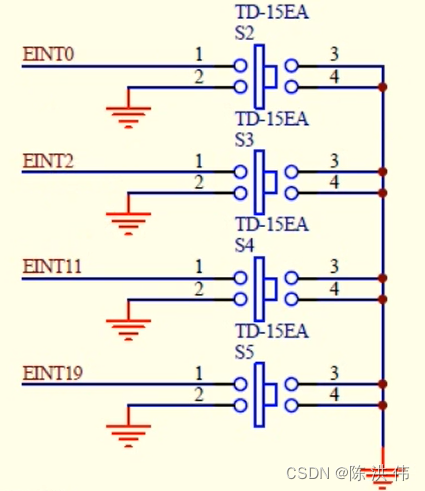
其中EINT11接到了GPG3,EINT19接到了接到了GPG11,
我们的内核里面抽象出了三个中断控制器gpf,gpg,interrupt-controller,那我们的四个按键对应的四个中断用到了哪几个中断控制器呢。之前我们说想要描述一个中断,我们可以在interrupt-parent指定他属于哪一个中断控制器,然后用interrupts属性执行他属于中断控制器中的哪一个,现在我们四个中断,其中EINT0 EINT2属于interrupt-controller,然后EINT11 EINT19属于GPG,那么我们就不用之前的方法去描述一个中断了,这时我们使用中断扩展属性
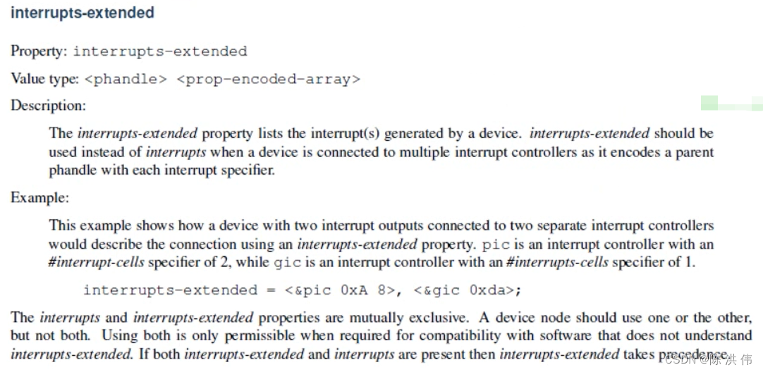
在这里面可以指定多个中断,比如<&pic oxA 8>是指这个中断是发给pic中断控制器的,然后0xA 8用来描述这个中断。
然后我们看一下我们的设备树文件中对于中断的描述
    buttons {
        compatible = "jz2440_button";
		eint-pins  = <&gpf 0 0>, <&gpf 2 0>, <&gpg 3 0>, <&gpg 11 0>;
        interrupts-extended = <&intc 0 0 0 3>,
                              <&intc 0 0 2 3>,
                              <&gpg 3 3>,
                              <&gpg 11 3>;
    };
其中<&intc 0 0 0 3>的intc用来表示中断控制器,0 0 0 3用来表示哪个中断,这四个数字的意义我们可以看一下内核里面自带的设备树的官方文档,\kernel\linux-4.19-rc3\Documentation\devicetree\bindings\interrupt-controller\samsung,s3c24xx-irq.txt
Samsung S3C24XX Interrupt Controllers

The S3C24XX SoCs contain a custom set of interrupt controllers providing a
varying number of interrupt sources. The set consists of a main- and sub-
controller and on newer SoCs even a second main controller.

Required properties:
- compatible: Compatible property value should be "samsung,s3c2410-irq"
  for machines before s3c2416 and "samsung,s3c2416-irq" for s3c2416 and later.

- reg: Physical base address of the controller and length of memory mapped
  region.

- interrupt-controller : Identifies the node as an interrupt controller

- #interrupt-cells : Specifies the number of cells needed to encode an
  interrupt source. The value shall be 4 and interrupt descriptor shall
  have the following format:
      <ctrl_num parent_irq ctrl_irq type>

  ctrl_num contains the controller to use:
      - 0 ... main controller
      - 1 ... sub controller
      - 2 ... second main controller on s3c2416 and s3c2450
  parent_irq contains the parent bit in the main controller and will be
             ignored in main controllers
  ctrl_irq contains the interrupt bit of the controller
  type contains the trigger type to use

Example:

	interrupt-controller@4a000000 {
		compatible = "samsung,s3c2410-irq";
		reg = <0x4a000000 0x100>;
		interrupt-controller;
		#interrupt-cells=<4>;
	};

	[...]

	serial@50000000 {
		compatible = "samsung,s3c2410-uart";
		reg = <0x50000000 0x4000>;
		interrupt-parent = <&subintc>;
		interrupts = <1 28 0 4>, <1 28 1 4>;
	};

	rtc@57000000 {
		compatible = "samsung,s3c2410-rtc";
		reg = <0x57000000 0x100>;
		interrupt-parent = <&intc>;
		interrupts = <0 30 0 3>, <0 8 0 3>;
	};
第一个值是用来分辨主控制器还是子控制器(我们之前说过硬件是有两个中断控制器的,但是软件上就一个,所以就用这个区分主控制器和子控制器),
第二个值:如果前面第一个值是子中断控制器,那么我们要制定子中断控制器是属于主中断控制器中的哪一个中断,这里我们的EINT0 EINT2都是直接连接到主中断控制器中的,所以这里第二个值我们都写了0.
第三个值就是描述这个中断的,就代表了是中断控制器中的哪一个中断。这里我们的EINT0的值是0表示是中断控制器中的第0个中断,EINT2的值是2表示是中断控制器中的第2个中断.
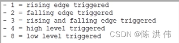
第四个值是中断类型。
上面是关于intc的四个数字的解释,下面看一下
<&gpg 3 3>,
<&gpg 11 3>;
&gpg是指中断控制器是gpg,在设备中会有一个节点来描述中断控制器gpg
然后关于后面的两个数字的含义也可以在内核的设备树文档中找到kernel\linux-4.19-rc3\Documentation\devicetree\bindings\pinctrl\samsung-pinctrl.txt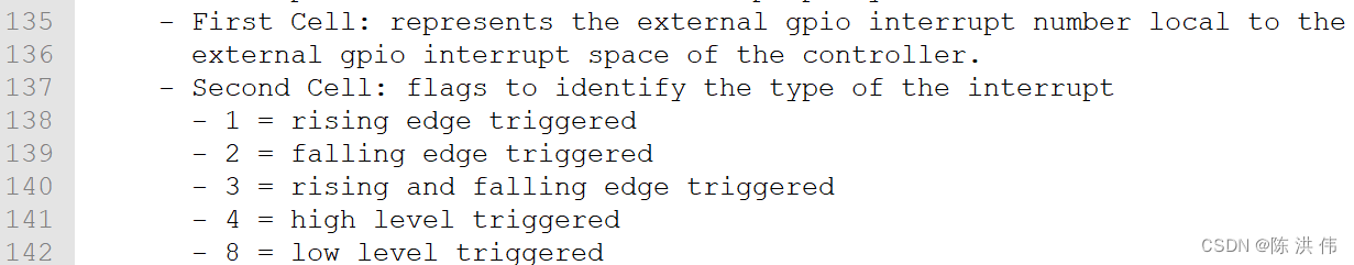
第一个数字表示连接到哪个管脚,第二个数字表示中断类型。
3 中断信息转换为中断号
我们的驱动程序需要使用中断号,那么设备树中的中断信息怎么转换为中断号,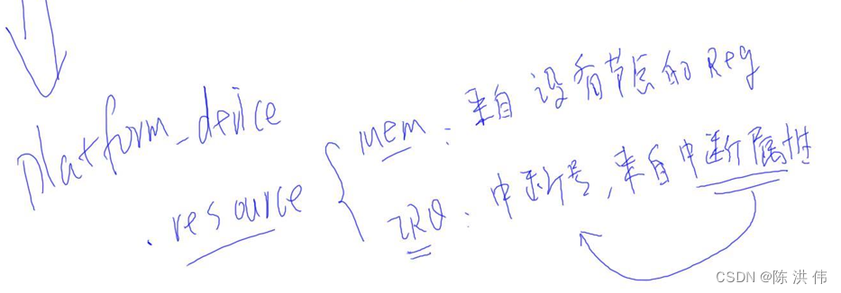
4 中断程序怎么使用中断号
我们的驱动程序从平台设备platform_device中把中断信息取出来。
static int buttons_probe(struct platform_device *pdev)
{
	struct device *dev = &pdev->dev;
	struct device_node *dp_node = dev->of_node;
	struct resource		*res;
	int i;

	for (i = 0; i < sizeof(pins_desc)/sizeof(pins_desc[0]); i++)
	{
		/* 根据platform_device的资源进行获得中断号,触发类型 */
		res = platform_get_resource(pdev, IORESOURCE_IRQ, i);
		if (res) {
			pins_desc[i].irq  = res->start;
			printk("get irq %d\n", pins_desc[i].irq);
		}
		else {
			printk("can not get irq res for eint0\n");
			return -1;
		}

		pins_desc[i].pin = of_get_named_gpio(dp_node, "eint-pins", i);
		printk("pins_desc[%d].pin = %d\n", i, pins_desc[i].pin);
	}

	return sixth_drv_init();
}
取出来的中断号保存在pins_desc中,
我们从设备树文件中还可以看到,我们的buttons还有一个eint-pins属性,
    buttons {
        compatible = "jz2440_button";
		eint-pins  = <&gpf 0 0>, <&gpf 2 0>, <&gpg 3 0>, <&gpg 11 0>;
        interrupts-extended = <&intc 0 0 0 3>,
                              <&intc 0 0 2 3>,
                              <&gpg 3 3>,
                              <&gpg 11 3>;
    };
这个是用来指定我们使用的是哪个引脚,我们使用of_get_named_gpio函数读取这个属性保存在pins_desc[i].pin中。
实验:
a.
把"002th_buttons_drv/jz2440_irq.dts" 放入内核 arch/arm/boot/dts目录,
在内核根目录下执行:
make dtbs   // 得到 arch/arm/boot/dts/jz2440_irq.dtb

使用上节视频的uImage或这个jz2440_irq.dtb启动内核;

b. 编译、测试驱动:
b.1 把 002th_buttons_drv 上传到ubuntu
b.2 编译驱动:
export  PATH=PATH=/usr/local/sbin:/usr/local/bin:/usr/sbin:/usr/bin:/sbin:/bin:/usr/games:/work/system/gcc-linaro-4.9.4-2017.01-x86_64_arm-linux-gnueabi/bin

cd 002th_buttons_drv
make   // 得到 buttons.ko

b.3 编译测试程序:
export PATH=/usr/local/sbin:/usr/local/bin:/usr/sbin:/usr/bin:/sbin:/bin:/usr/games:/usr/local/games:/usr/local/arm/4.3.2/bin

cd 002th_buttons_drv

arm-linux-gcc -o buttons_test  buttons_test.c

b.4 测试:
insmod buttons.ko
./buttons_test &
然后按键


 1829
1829


 被折叠的 条评论
为什么被折叠?
被折叠的 条评论
为什么被折叠?
 到【灌水乐园】发言


