


The Layout System布局系统
布局系统主要负责定位和缩放在QCustomPlot上的布局元素比如坐标轴矩形,图例和Plot标题。
Classes and mechanisms类和机制
布局系统基于抽象基类QCPLayoutElement.所有参与布局系统的对象都派生自此类,直接的或间接的。
布局元素的矩形
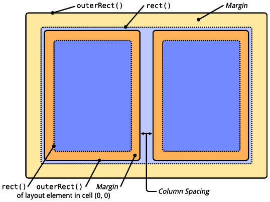
一个布局元素是一个矩形对象通过两个矩形被描述:内部矩形(QCPLayoutElement::rect)和外部矩形(QCPLayoutElement::setOuterRect)。内部矩形被自动计算通过(QCPLayoutElement::setMargins)来自外矩形的内部margin.内部的矩形是主要内容当margin区域被留下空白或者服务于显示外部图形。例如QCPAxisRect位于四个主要轴的内部矩形。因此graph在他里面并且坐标轴标签和刻度标签在margin区域。
如果多个布局元素被相互安排在旁边或者下面,它可能期望以它们内部矩形的特定的边对齐。因为它们有不同的自动margin,这通常并非如此。这个类QCPMarginGroup和QCPLayoutElement::setMarginGroup修补了这个通过允许同步多个margin。
margins
每一个布局元素都提供一个自动决定它margin的机制。它被实现用QCPLayoutElement::calculateAutoMargin带有一个QCP::MarginSide的函数并且返回一个整型值,代表指定边的真实的margin.自动计算的margin将被用在QCPLayoutElement::setMargins指定的边。默认它被设置为QCP::smAll意味着自动计算的margin被用于四个边。在这种情况下,最小的margin用QCPLayoutElement::setMinimumMargins设置。为了阻止自动margin机制设置更小的margin比期望的情况。如果自动计算的margin不被设置到指定的边,指定边的margin可以直接使用QCPlayoutElement::setMargins设置。
布局
如前所说,一个QCPLayoutElement可能有任意数量的子布局元素和从原则上说只有一个管理/安排这些子元素。这个类是QCPLayout的子类。QCPLayoutElement本身没有可视化。它定义了add,remove和管理子布局元素。QCPLayout不是一个可用的布局。它是具体布局的抽象基类像QCPLayoutGrid在网格线中安排它的子元素并且QCPLayoutInset允许将子元素自由地放置在它的内部矩形。
由于QCPLayout本身就是一个布局元素,通过这种方式可以创建复杂的继承,提供灵活的安排。
下面是一个简单的略图默认的QCPLayoutGrid可以通过QCustomPlot::plotLayout来访问。它展示了在网格布局内部如何放置两个布局元素相邻的(0,0)和(0,1)
顶层Plot布局
每一个QCustomPlot有一个顶层布局器类型是QCPLayoutGrid。它可以通过QCustomPlot::plotLayout来访问并且包含了所有的布局元素.默认这个顶级布局器包含了一个cell可以容纳主要的坐标轴矩形。
Examples
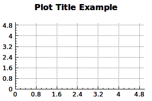
添加一个plot标题是一个典型并且见得的雷子对于了解布局系统的基本工作。
QCPPlotTitle*title = new QCPPlotTitle(customPlot);
title->setText("Plot Title Example");
title->setFont(QFont("sans",12,QFont::Bold));
customPlot->plotLayout()->insertRow(0);
布局系统主要负责定位和缩放在QCustomPlot上的布局元素比如坐标轴矩形,图例和Plot标题。
Classes and mechanisms类和机制
布局系统基于抽象基类QCPLayoutElement.所有参与布局系统的对象都派生自此类,直接的或间接的。
布局元素的矩形
一个布局元素是一个矩形对象通过两个矩形被描述:内部矩形(QCPLayoutElement::rect)和外部矩形(QCPLayoutElement::setOuterRect)。内部矩形被自动计算通过(QCPLayoutElement::setMargins)来自外矩形的内部margin.内部的矩形是主要内容当margin区域被留下空白或者服务于显示外部图形。例如QCPAxisRect位于四个主要轴的内部矩形。因此graph在他里面并且坐标轴标签和刻度标签在margin区域。
如果多个布局元素被相互安排在旁边或者下面,它可能期望以它们内部矩形的特定的边对齐。因为它们有不同的自动margin,这通常并非如此。这个类QCPMarginGroup和QCPLayoutElement::setMarginGroup修补了这个通过允许同步多个margin。
margins
每一个布局元素都提供一个自动决定它margin的机制。它被实现用QCPLayoutElement::calculateAutoMargin带有一个QCP::MarginSide的函数并且返回一个整型值,代表指定边的真实的margin.自动计算的margin将被用在QCPLayoutElement::setMargins指定的边。默认它被设置为QCP::smAll意味着自动计算的margin被用于四个边。在这种情况下,最小的margin用QCPLayoutElement::setMinimumMargins设置。为了阻止自动margin机制设置更小的margin比期望的情况。如果自动计算的margin不被设置到指定的边,指定边的margin可以直接使用QCPlayoutElement::setMargins设置。
布局
如前所说,一个QCPLayoutElement可能有任意数量的子布局元素和从原则上说只有一个管理/安排这些子元素。这个类是QCPLayout的子类。QCPLayoutElement本身没有可视化。它定义了add,remove和管理子布局元素。QCPLayout不是一个可用的布局。它是具体布局的抽象基类像QCPLayoutGrid在网格线中安排它的子元素并且QCPLayoutInset允许将子元素自由地放置在它的内部矩形。
由于QCPLayout本身就是一个布局元素,通过这种方式可以创建复杂的继承,提供灵活的安排。
下面是一个简单的略图默认的QCPLayoutGrid可以通过QCustomPlot::plotLayout来访问。它展示了在网格布局内部如何放置两个布局元素相邻的(0,0)和(0,1)
顶层Plot布局
每一个QCustomPlot有一个顶层布局器类型是QCPLayoutGrid。它可以通过QCustomPlot::plotLayout来访问并且包含了所有的布局元素.默认这个顶级布局器包含了一个cell可以容纳主要的坐标轴矩形。
Examples
添加一个plot标题是一个典型并且见得的雷子对于了解布局系统的基本工作。
QCPPlotTitle*title = new QCPPlotTitle(customPlot);
title->setText("Plot Title Example");
title->setFont(QFont("sans",12,QFont::Bold));
customPlot->plotLayout()->insertRow(0);
customPlot->plotLayout()->addElement(0,0,title);
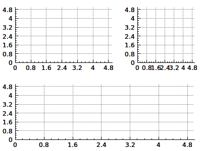
安排多个坐标轴矩形实际上是布局系统的重要目的。


 479
479

 被折叠的 条评论
为什么被折叠?
被折叠的 条评论
为什么被折叠?
 到【灌水乐园】发言


