


写作说明:
1. 本文主要记录学习 Matlab - Robotics System Toolbox [1]的过程,就其中的一些重要知识点做相关记录。方便后期供自己与他人进行学习。
2. 由于 Matlab 官方只提供了该工具箱的部分示例,本系列文章将会在记录完所有的官方示例代码后,添加自己的一些机器人仿真代码,进行更多的开发尝试。
机器人算法
1 机械臂算法
1.1 逆向运动学实现轨迹控制
本部分教程主要讲解了如何来构建一个机械臂逆向运动学控制的 Matlab-Simulink 系统。
导入官方提供的教学模型,如下所示。
open_system('IKTrajectoryControlExample.slx');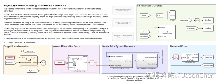
思考:
- 说实话,看了 Matlab 官方搭建的示例机器人控制系统模型文件,真的觉得代码写的规范且漂亮。自己写 Simulink 代码还是有很多需要提升的地方。
整个控制系统由4个主要部分组成:
- 目标位置生成模块
- 逆运动学计算模块
- 操作臂动力学模型模块
- 位置测量(或正运动学)模型模块
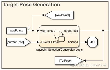
目标位置生成模块
此模块使用状态流程图来选择机械臂的目标轨迹以及当前目标位置。一旦机械臂到达目标位置附近,并处于设定的公差范围内,状态流程组件则会将目标调整到下一个目标点。当没有更多的目标位置点可供选择时,该模块将终止仿真。
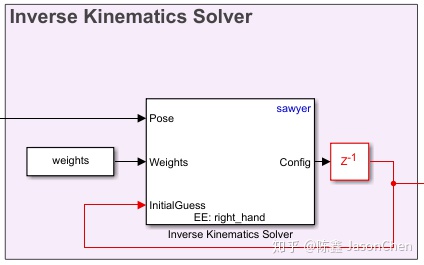
逆运动学计算模块
逆动力学计算模块计算一组关节角度,以生成机械臂末端执行器所需的构型(configuration)。
操作臂动力学模型模块
机械臂动力学模型模块由两部分组成,一部分计算得到输出的转矩,另一部分将给定转矩信号输出到机械臂的动力学模型,得到机械臂的测量构型(configuration)。
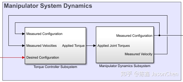
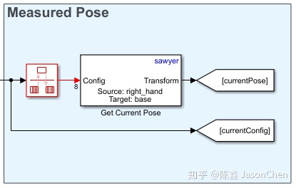
位置测量(或正运动学)模型模块
位置测量(或正运动学)模型模块从机械臂模型中获取关节角度数,并将其计算转换为一个当前的末端位置。
1.1.1 模型参数初始化
% Import the manipulator as a rigidBodyTree Object
sawyer = importrobot('sawyer.urdf');
sawyer.DataFormat = 'column';

% Define end-effector body name
eeName = 'right_hand';

% Define the number of joints in the manipulator
numJoints = 8;

% Visualize the manipulator
show(sawyer);
xlim([-1.00 1.00])
ylim([-1.00 1.00]);
zlim([-1.02 0.98]);
view([128.88 10.45]);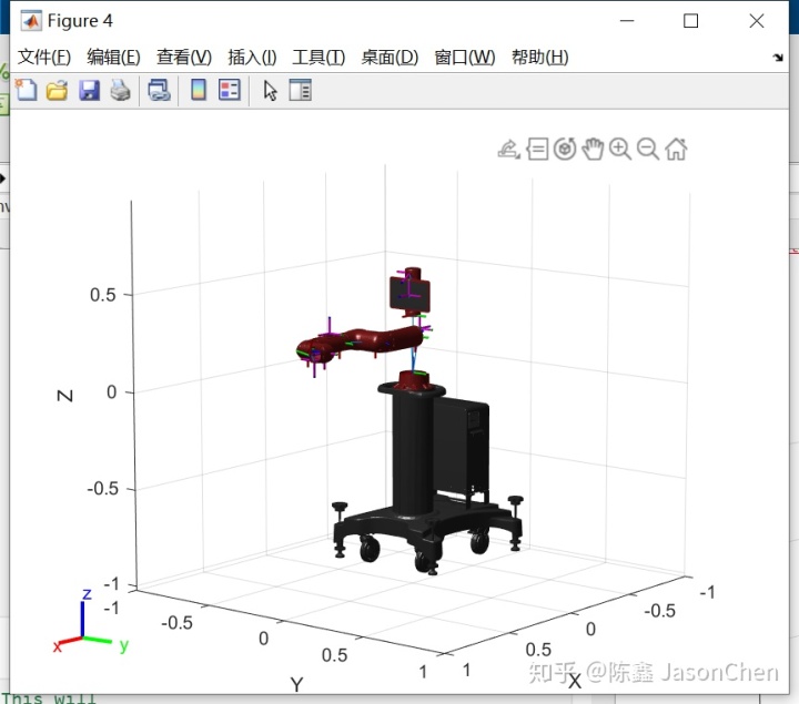
% Initialize size of q0, the robot joint configuration at t=0. This will
% later be replaced by the first waypoint.
q0 = zeros(numJoints,1);

% Define a sampling rate for the simulation.
Ts = .01;

% Define a [1x6] vector of relative weights on the orientation and
% position error for the inverse kinematics solver.
weights = ones(1,6);

% Transform the first waypoint to a Homogenous Transform Matrix for initialization
initTargetPose = eul2tform(wayPoints(1,4:6));
initTargetPose(1:3,end) = wayPoints(1,1:3)';

% Solve for q0 such that the manipulator begins at the first waypoint
ik = inverseKinematics('RigidBodyTree',sawyer);
[q0,solInfo] = ik(eeName,initTargetPose,weights,q0);
1.2 碰撞检测
目标:生成一个 collision-free 轨迹。
1.2.1 创建虚拟环境
可以创建一个简单的带有碰撞物的环境。例如,假设机器人在一个工作空间中,目标是将被操作对象从一个桌子移动到另一个桌子,同时避免悬挂在空中的一个球体。这些对象可以建模为两个长方体和一个球体。可以使用 collisionMesh 对象创建更复杂的环境。
% Create two platforms
platform1 = collisionBox(0.5,0.5,0.25);
platform1.Pose = trvec2tform([-0.5 0.4 0.2]);

platform2 = collisionBox(0.5,0.5,0.25);
platform2.Pose = trvec2tform([0.5 0.2 0.2]);

% Add a light fixture, modeled as a sphere
lightFixture = collisionSphere(0.1);
lightFixture.Pose = trvec2tform([.2 0 1]);

% Store in a cell array for collision-checking
worldCollisionArray = {platform1 platform2 lightFixture};

% Visualize the environment using a helper function that iterates through the collision array.
exampleHelperVisualizeCollisionEnvironment(worldCollisionArray);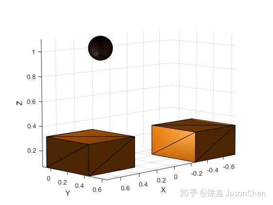
1.2.2 添加机器人模型
robot = loadrobot("kinovaGen3","DataFormat","column","Gravity",[0 0 -9.81]);
ax = exampleHelperVisualizeCollisionEnvironment(worldCollisionArray);
show(robot,homeConfiguration(robot),"Parent",ax);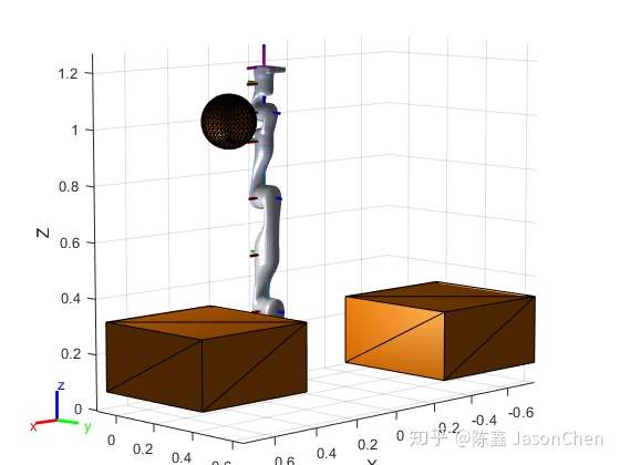
1.2.3 设置机器人为一系列的碰撞体
% Generate an array of collision objects from the visuals of the associated tree
collisionArray = exampleHelperManipCollisionsFromVisuals(robot);
1.2.4 生成轨迹并检查碰撞
startPose = trvec2tform([-0.5,0.5,0.4])*axang2tform([1 0 0 pi]);
endPose = trvec2tform([0.5,0.2,0.4])*axang2tform([1 0 0 pi]);

% Use a fixed random seed to ensure repeatable results
rng(0);
ik = inverseKinematics("RigidBodyTree",robot);
weights = ones(1,6);
startConfig = ik("EndEffector_Link",startPose,weights,robot.homeConfiguration);
endConfig = ik("EndEffector_Link",endPose,weights,robot.homeConfiguration);

% Show initial and final positions
show(robot,startConfig);
show(robot,endConfig);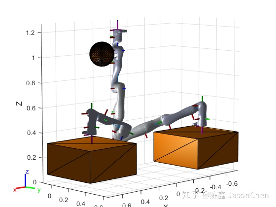
% Use a trapezoidal velocity profile to generate a smooth trajectory from the home position to the start position, and then to the end position. Use collision checking to see whether this results in any collisions.
q = trapveltraj([homeConfiguration(robot),startConfig,endConfig],200,"EndTime",2);

%Initialize outputs
isCollision = false(length(q),1); % Check whether each pose is in collision
selfCollisionPairIdx = cell(length(q),1); % Provide the bodies that are in collision
worldCollisionPairIdx = cell(length(q),1); % Provide the bodies that are in collision

for i = 1:length(q)
    [isCollision(i),selfCollisionPairIdx{i},worldCollisionPairIdx{i}] = exampleHelperManipCheckCollisions(robot,collisionArray,worldCollisionArray,q(:,i),false);
end
isTrajectoryInCollision = any(isCollision)
1.2.5 查看问题(碰撞)构型
problemIdx1 = find(isCollision,1);
problemIdx2 = find(isCollision,1,"last");

% Identify the problem rigid bodies
problemBodies1 = [selfCollisionPairIdx{problemIdx1} worldCollisionPairIdx{problemIdx1}*[1 0]'];
problemBodies2 = [selfCollisionPairIdx{problemIdx2} worldCollisionPairIdx{problemIdx2}*[1 0]'];

% Visualize the environment
ax = exampleHelperVisualizeCollisionEnvironment(worldCollisionArray);

% Add the robots & highlight the problem bodies
show(robot,q(:,problemIdx1),"Parent",ax,"PreservePlot",false);
exampleHelperHighlightCollisionBodies(robot,problemBodies1,ax);
show(robot,q(:,problemIdx2),"Parent"',ax);
exampleHelperHighlightCollisionBodies(robot,problemBodies2,ax);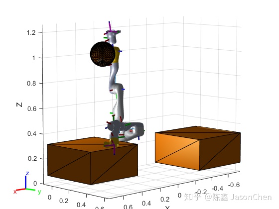
1.2.6 使用中间点避免碰撞出现
intermediatePose1 = trvec2tform([-.3 -.2 .6])*axang2tform([0 1 0 -pi/4]); % Out and around the sphere
intermediatePose2 = trvec2tform([0.2,0.2,0.6])*axang2tform([1 0 0 pi]); % Come in from above

intermediateConfig1 = ik("EndEffector_Link",intermediatePose1,weights,q(:,problemIdx1));
intermediateConfig2 = ik("EndEffector_Link",intermediatePose2,weights,q(:,problemIdx2));

% Show the new intermediate poses
ax = exampleHelperVisualizeCollisionEnvironment(worldCollisionArray);
show(robot,intermediateConfig1,"Parent",ax,"PreservePlot",false);
show(robot,intermediateConfig2,"Parent",ax);

% Generate a new trajectory.
[q,qd,qdd,t] = trapveltraj([homeConfiguration(robot),intermediateConfig1,startConfig,intermediateConfig2,endConfig],200,"EndTime",2);

% Verify that it is collision-free.
% Initialize outputs
isCollision = false(length(q),1); % Check whether each pose is in collision
collisionPairIdx = cell(length(q),1); % Provide the bodies that are in collision
for i = 1:length(q)
    [isCollision(i),collisionPairIdx{i}] = exampleHelperManipCheckCollisions(robot,collisionArray,worldCollisionArray,q(:,i),false);
end
isTrajectoryInCollision = any(isCollision)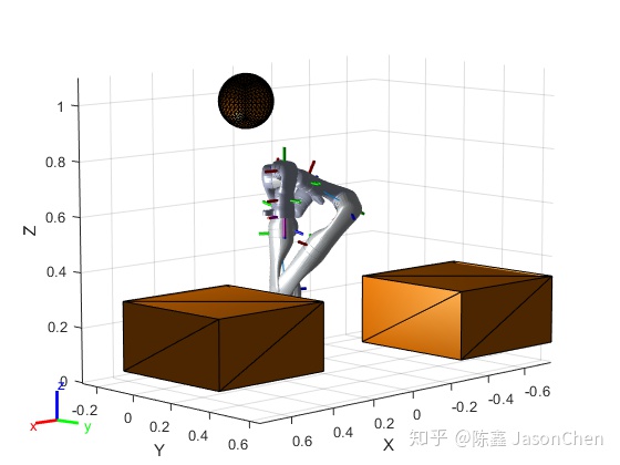
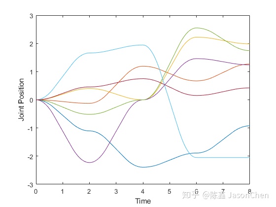
1.2.7 查看生成的轨迹
% Plot the environment
ax2 = exampleHelperVisualizeCollisionEnvironment(worldCollisionArray);

% Visualize the robot in its home configuration
show(robot,startConfig,"Parent",ax2);

% Update the axis size
axis equal

% Loop through the other positions
for i = 1:length(q)
    show(robot,q(:,i),"Parent",ax2,"PreservePlot",false);

    % Update the figure
    drawnow
end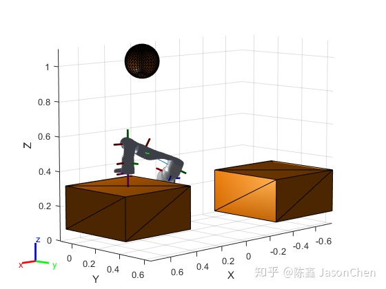
1.3 安全轨迹跟踪控制
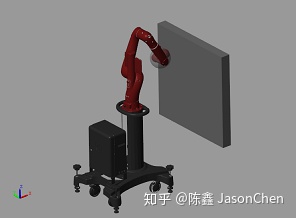
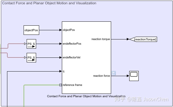
在本例中,您将运行一个模型,该模型使用机械臂算法块实现具有关节位置和速度反馈的计算扭矩控制器。控制器接收来自模拟机器人(使用Simscape多体实现)的关节位置和速度信息,并发送扭矩指令,从而驱动机器人沿着给定的关节轨迹运动。
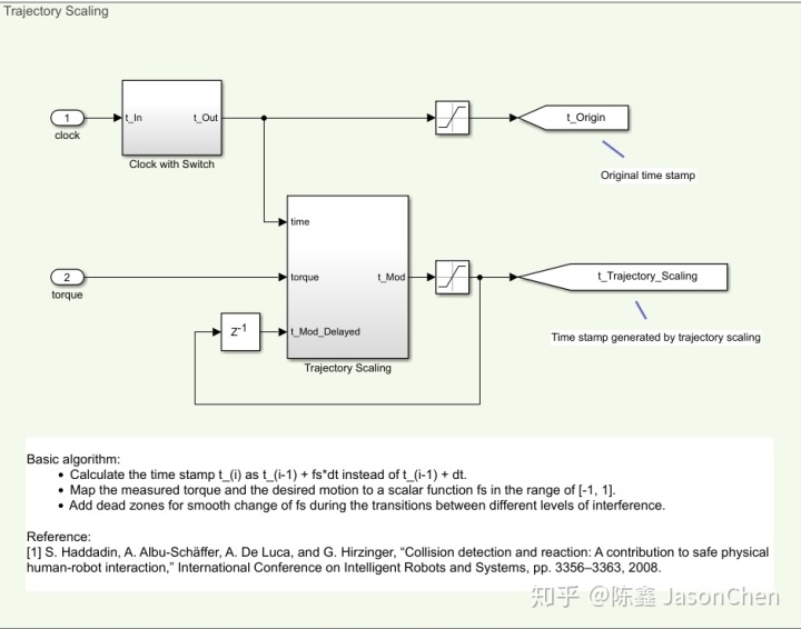
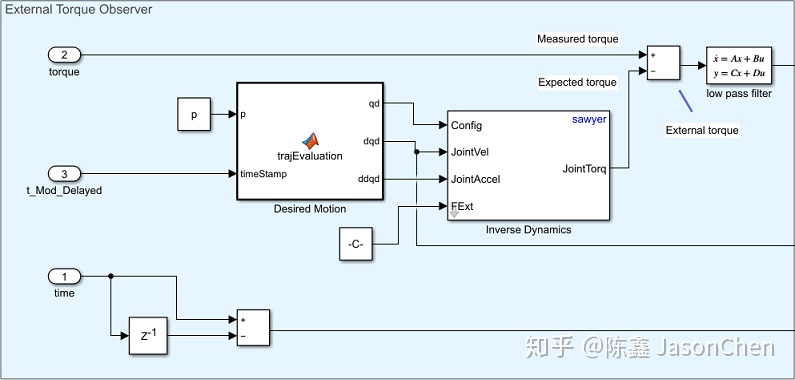
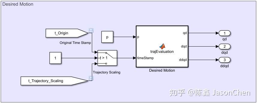
在机器人前面放置一个平面物体。在执行轨迹跟踪运动控制时,机器人手臂的末端执行器与之会发生碰撞。在没有任何附加设置的情况下,由于与物体碰撞而增加的扭矩可能会对机器人或物体造成损坏。为了实现安全的轨迹跟踪,在给控制器分配所需运动时,建立轨迹缩放块(trajectory scaling block)来调整时间戳。您可以在模型运行时调整一些参数并与机器人交互,观察对模拟机器人的影响。
1.3.1 设置机器人模型
% This example uses a model of the Rethink Sawyer, a 7 degree-of-freedom robot manipulator. Call importrobot to generate a rigidBodyTree model from a description stored in a Unified Robot Description Format (URDF) file. Set the DataFormat and Gravity properties to be consistent with Simscape.
sawyer = importrobot('sawyer.urdf');
sawyer.removeBody('head');
sawyer.DataFormat = 'column';
sawyer.Gravity = [0, 0, -9.80665];
1.3.2 轨迹生成与配置
% First, assign the start time and duration for the trajectory.
tStart = 0.5;
tDuration = 3;
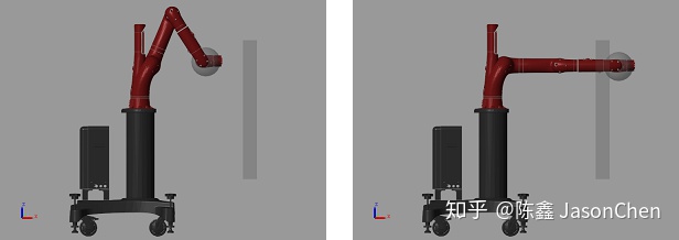
% Next, assign the initial and target configuration. q0 is the initial configuration and q1 is the target configuration.
q0 = [0; -1.18; 0; 2.18; 0; -1.0008; 3.3161];
q1 = zeros(7,1);这两幅图展示了起始位置和终止位置,可以看到是会与环境物体碰撞的。
% Use exampleHelperPolynomialTrajectory to generate the desired motion trajectory for each joint. exampleHelperPolynomialTrajectory generates the polynomial coefficients of a trajectory that satisfies the desired joint position, zero velocity and zero acceleration based on the initial and target configurations and the trajectory duration.
p = exampleHelperPolynomialTrajectory(q0,q1,tDuration);
1.3.3 Simulink 控制模型
open_system('robotSafeTrajectoryTracking.slx');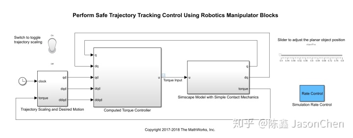
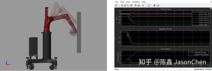
当不开启控制的时候,机器人碰到障碍物,会产生极大的力矩输出。
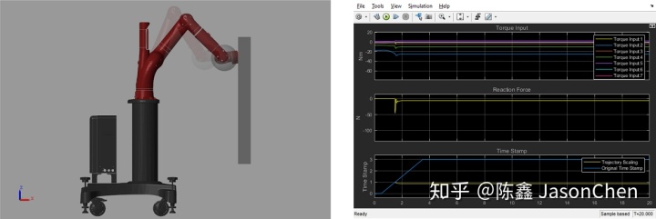
当开启控制的时候,机器人碰到障碍物,当输出力矩大于某一个值后,会减小到合理值。
1.4 结合ROS逆向运动学和Action进行轨迹规划(略)
2 移动机器人算法(略)
3. UAV 算法(略)
思考:
- 从 Matlab Robotics System Toolbox 的学习中了解到的最重要的一点就是 Matlab Simulink 搭建动力学模型的快速性。因为 Toolbox 中提供了一系列的工具模块用于计算机器人的构型和机器人的动力学模型。这样,我们可以利用 Matlab 飞快地验证我们的实验样机的算法是否正确。
- 同时,了解到的还有 Matlab Robotics System Toolbox 支持 Simscape 导入模型。而 Simscape 支持 urdf 导入模型。这样,我们创建机器人的仿真模型可以有如下流程。
1. 使用 solidworks 进行机器人建模。
2. 使用 solidworks urdf 插件得到机器人模型文件。
3. 使用 simscape 导入模型文件,建立模型,查看模型是否有错误。
4. 使用 simulink robotics system toolbox 进行机器人的正逆运动学,正逆动力学解算。
5. 搭建控制系统,仿真机器人控制。
6. 如果需要做控制,则插上外设,控制真实的机器人。
(Matlab 真的是实现了从仿真到实际机器的整个环节,厉害厉害,佩服佩服,大佬大佬,学习学习 :P)
- 唯一可能在实际工作场景中需要注意的就是实际机器的动力学模型可能需要我们来自己推导,当然,也可以进一步查询 Matlab 源码,看是用哪种算法来做的(非常有必要,接下来会考虑实践)。
参考
- ^Matlab - Robotics System Toolbox https://www.mathworks.com/products/robotics.html


 698
698

 被折叠的 条评论
为什么被折叠?
被折叠的 条评论
为什么被折叠?
 到【灌水乐园】发言


