


文章目录
概述
- 多协议标签交换MPLS(Multiprotocol Label Switching)是一种IP(Internet Protocol)骨干网技术
- 它实际上是一种隧道技术。这种技术不仅支持多种高层协议与业务,而且在一定程度上可以保证信息传输的安全性。
技术产生背景
-
90年代,由于当时
流量快速增长,硬件技术有限,传统的最长匹配法成为网络转发的瓶颈。 -
快速路由技术成成当时研发热点。就在此时,ATM迅速发展,采用标签转发,解决了路由转发的弊端,但是,由于
ATM配置复杂,部署成本高,很难普及。 -
后来结合了IP转发的有点和ATM的优点,
IETF确定了MPLS协议作为标准协议。采用短而定长的标签转发,同时 MPLS 可以扩展很多网络协议,IPV6 IPX -
MPLS 应用
- MPLS TE 流量工程,–可操控的–
- MPLS qos
- MPLS 隧道
-
基本原理:
- lsp 标签转发路径
- 原理:进入LER路由器,打上标签,发给下一台设备,打上新的标签,直到最后,玻璃标签,IP 转发
-
MPLS 转发动作
- 动作
- push 压入出标签
- swap 交换 标签转发表,替换标签 进来的100 ,转出200
- pop 弹出,打上3的标签
- 动作
-
控制平面
- 路由协议–>路由表
- 标签分发协议
-
数据平面:
- FIB表:转发信息表
- LFIB:标签转发信息表
- NHLFE :下一跳标签转发项
- FEC 转发等价类: 以等价的方式处理的一组数据分组
- 目的前缀相同的数据分组,比如:10.1.1.0/24 报文属于一个FEC
MPLS 基本结构
- 图
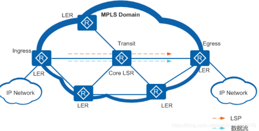
LER --Ingress–入接点
LSP —Transit 中间节点
LER–出接口–Egress
MPLS 基本转发过程
- 如图:
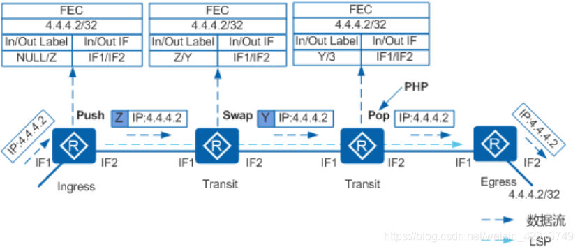
1.当Ingress节点收到目的地址为4.4.4.2的IP报文,压入标签Z并转发。
2.Transit节点收到该标签报文,进行标签交换,将标签Z换成标签Y。
3.倒数第二跳Transit节点收到带标签Y的报文。因为Egress分给它的标签值为3,所以进行PHP操作,弹出标签Y并转发报文。从倒数第二跳转发给Egress的报文以IP报文形式传输。
4.Egress节点收到该IP报文,将其转发给目的地4.4.4.2/32。
MPLS 详细转发过程
- 图:R1、R2、R3、R4
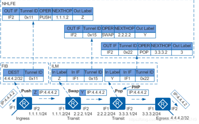
- 详细过程
- 当
R1收到一个目的ip 为4.4.4.2/24的数据包,首先,查找它的FIB表(转发信息表,看前缀和Tunnel id),如果看到Tunnel ID值为0x0,则进入正常的IP转发流程;如果Tunnel ID值不为0x0,则进入MPLS转发流程。由图可知,tunnel id 为0x11,所以根据Tunnle id继续查找NHLFE表(下一跳转发信息表,看到出接口、tunnel id、操作动作{push、swap、pop}、下一跳、出标签),压入出标签Z,发给下一跳1.1.1.2/24,到达R2 - 当
R2收到一个带有标签的帧,并不会查看FIB表(它会看帧,不会查FIB表),此时,直接查找ILM表(入标签映射ILM(Incoming Label Map)包涵:入标签、入接口、Tunnel ID),判断tunnel id 是否为 0x0 ,此时看到Tunnel id 不为0,再次查看NHLFE表(下一跳转发信息表,看到出接口、tunnel id、操作动作{push、swap、pop}、下一跳、出标签),将Z标签替换成Y标签,发给下一跳设备2.2.2.2/24,到达R3 - 当
R3收到一个带标签Y的帧,,此时,直接查找ILM表(入标签映射ILM(Incoming Label Map)包涵:入标签、入接口、Tunnel ID),判断tunnel id 是否为 0x0 ,此时看到Tunnel id 不为0,再次查看NHLFE表(下一跳转发信息表,看到出接口、tunnel id、操作动作{push、swap、pop}、下一跳、出标签),操作类型为PHP(次末跳弹出–R4分发的标签3给R3)看到出标签为3,所以弹出标签,发给下一跳3.3.3.2/24,到达R4. - 当
R4看到没有标签,就会根据查找FIB表,对应的tunnel id 是0x0,直接走路由,发给对应的设备
- 当
mpls 标签模式
-
帧模式:打在帧包头和ip报头
-
label 20bit
-
exp 3bit 扩展 qos
-
S 1 bit 栈地位
-
ethernet:0x0800 ipv4
0x8847MPLS 单播报文- 0x
8848MPLS 多播报文
-
PPP 0x8021 ipv4
-
0x8281mpls 单播报文 -
0x8283MPLS多播报文- 标签嵌套应用
- MPLS V-P-N
- MPLS TE
- 标签嵌套应用
-
-
-
ttl 8bit
-
-
信元模式–用于ATM
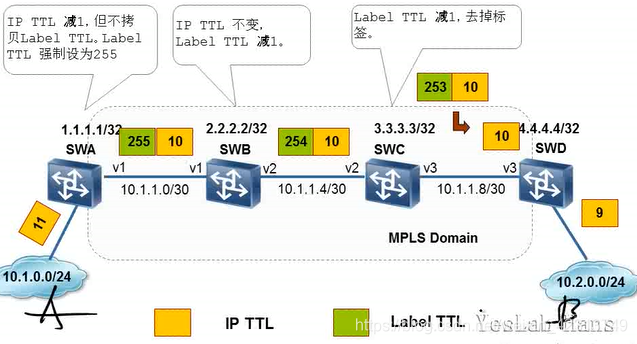
MPLS放环方法:
-
默认:
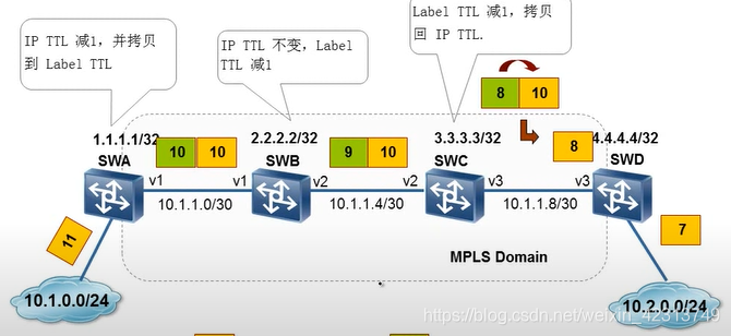
IP ttl 减一,并拷贝到label ttl
中间lsp ip TTL 不变,lable TTL 减1
ler label ttl 减1 ,拷贝会IP TTL -
第二种:不拷贝,打上255,IP TTL 不变,label ttl 减1 ,出去:去掉标签,ip ttl 不变
总结:ip数据包进入MPLS域的时候,首先查看FIB表,中间路由器转发,查找LFIB 表(标签转发信息表–华为查的是LIM 表–LSP).
LSP建立方式
-
静态LSP的建立:
- 静态LSP是用户通过手工为各个转发等价类分配标签而建立的。
- 由于静态LSP各节点上不能相互感知到整个LSP的情况,因此静态LSP是一个本地的概念。
- 配置思路:
- 工指定静态LSP的标签时,需要遵循以下原则:一条LSP上,上游LSR出标签的值与下游LSR入标签的值相同
- LSP是一条单向路径,因此需要在数据传输的两个方向上分别配置一条静态LSP
- 无需配置路由协议,只需要在入节点配置配置到达FEC目的地址的静态路由即可
- 基本命令:
-[RouterA] ip route-static 21.1.1.0 24 10.1.1.2#配置静态
- 基本命令:
- 配置思路:
-
动态LSP的建立:
- LDP
- Label Distribution Protocol)是专为标签发布而制定的协议
- 根据IGP(Interior Gateway Protocol)、BGP(Border Gateway Protocol)路由信息通过逐跳方式建立LSP
- RSVP-TE
- RSVP-TE(Resource Reservation Protocol Traffic Engineering)是对RSVP的扩展,用于建立基于约束的LSP
- •MP-BGP
- MP-BGP(Multiprotocol Border Gateway Protocol)是在BGP协议基础上扩展的协议。
- MP-BGP支持为MPLS隧道业务中私网路由和跨域隧道的标签路由分配标签。
- LDP
-
动态LSP的基本建立过程:
- DU:下游自主分发
- Dod:下游按需分发
LDP 协议及原理,思科–TDP
-
标签如何形成?
- LDP 是用来在LSR之间建立LDP会话并交换Lable/FEC 映射信息
- 分配标签,
为FEC分配标签,通过前缀分配FEC
-
消息类型 4种 发现,会话 通告 告警
-
Discovery
发现协议类型:宣告或者维护网络中的LSP的存在hello报文 发现邻居的
-
会话协议类型建立、维护和终止 LDP 邻居间的LDP 会话initialization协商参数keepalive tcp连接完整性
-
通告协议类型`:生成、改变和删除FEC的标签映射- address 宣告接口地址
- address withdraw 撤销接口地址
- label mapping 宣告FEC/label 映射信息
- label Request 请求FEC标签映射
- label Abort Request:终止未完成的label requset信息
- label withdraw 撤销FEC/label 映射
- LABEL Release 释放标签
-
Notification:宣告告警 和错误信息notification通知错误信息
-
-
ldp 邻居发现机制
-
基本发现机制
- 直接连在同链路的上LSR邻居,,组播发现–直连
-
发现 hello 5s/次 224.0.0.2,源目的端口号都是 646 UDP
-
TCP三次连接
目的端口号646 源端口号任意 -
主动端(TCP 646 )IP 地址大的去发送,回复一个Keepalive 报文确认
-
- 直接连在同链路的上LSR邻居,,组播发现–直连
-
扩展发现机制
发现非直连的LSR邻居 单播 —非直连
-
基本配置
A:mpls lsr-id 1.1.1.1 #必须手工配置,本地可达的地址
mpls #全局开启mpls功能
mpls ldp
int e0/0 #接口开启mpls
mpls
mpls ldp
display ldp secssion 查看ldp 会话
-
LDP 的状态机
- noexistent 没有hello 或者发了还没表项
- 初始化 initialization
- openSent
- openRec
- operational
-
无连接:传输数据前没有建好的路径,tunnel
-
有连接:需要tcp 连接
MPLS 隧道
- 是一种L3 隧道 技术
- 使用BGP在服务提供商骨干网上发布隧道路由,
原理描述
-
基本模型构成
- CE:用户网络边缘设备
- PE:服务提供商网络边缘设备
- P :服务提供商网络中的骨干设备
-
图:
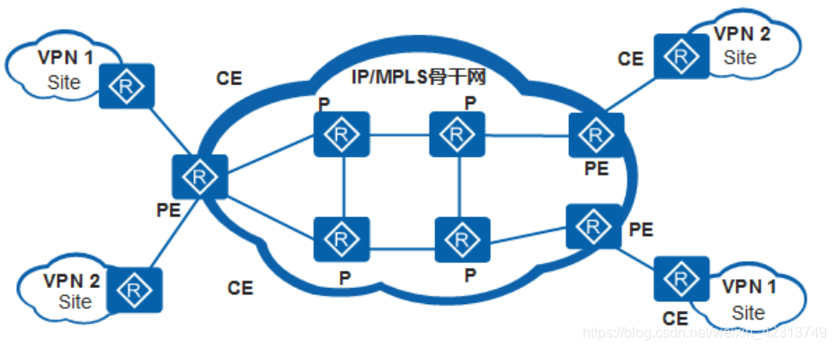
site:
指相互之间具备IP 连通性的一组IP系统,,且该系统IP连通性不需通过ISP实现
–本地有效
-
特点:
- l3 MPLS 模型特点:
- 隧道承建:客户设备透明,运营商设备维护
- 路由维护:客户设备维护,运营商设备维护
- 数据封装:MPLS 标签报
- l3 MPLS 模型特点:
-
L3 MPLS隧道模型
-
的有优势和劣势
- 优势:由运营商维护客户路由,降低管理成本
- 劣势:路由信息被运营商获取,数据缺乏加密
-
L3 MPLS 隧道遇到的问题
-
如何做到同一台PE设备的不同客户CE设备之间的隔离----instance–即为隧道 路由的转发表VRF
-
如何PE设备与CE设备之间维护路由信息
- igp --PE上要双向引入
- BGP 不需要引入
-
如何在公网上传递客户私有路由
- MP-BGP–多协议BGP
- 采用地址族来区分不同的网络层协议,以变争取处理V-P-N-IPV4路由
- MP-BGP–多协议BGP
-
通告重叠的的客户私有路由?
- 不同的隧道独立管理自己的地址范围,地址可以重叠:
- 2个隧道 没有共同的site。
- 2个隧道有共同的site,但此site的设备不与2个隧道中使用的地址空间的设备互访
- 不同的隧道独立管理自己的地址范围,地址可以重叠:
-
RD===区分相同地址空间的IPv4前缀(区分重叠的路由信息)
- 64bit
- V-P-N-V4 address=RD +ipv4地址
-
RT====Router Target–BGP的扩展团体属性
- 用于控制V-P-N路由信息的发布,将PE设备上接受到的V-P-Nv4前缀正确通告给CE设备
- Export Target==通告时作为团体属性携带
- Import Target==用于接受具有特定RT值的V-P-Nv4路由前缀
- 用于控制V-P-N路由信息的发布,将PE设备上接受到的V-P-Nv4前缀正确通告给CE设备
-
如何在公网上转发客户数据?
-
-
基本原理----功能组件
- PE 设备 隧道-instance
PE-CE间路由协议及PE设备路由重分发 - PE 设备之间P-BGP
- 骨干网络P与PE间IGP
- 骨干网络P与PE间LDP
- PE 设备 隧道-instance
配置命令
基本配置
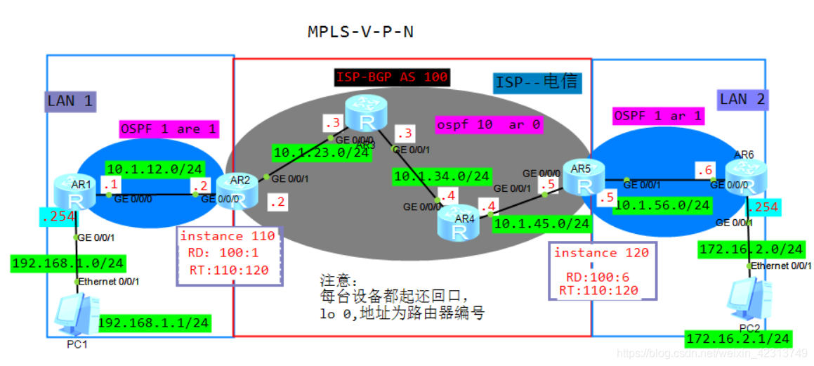
- ip 地址如图所示
<R1>undo terminal mo
<R1>undo terminal monitor
  [R1]dis ip int brief
*down: administratively down
^down: standby
(l): loopback
(s): spoofing
The number of interface that is UP in Physical is 4
The number of interface that is DOWN in Physical is 1
The number of interface that is UP in Protocol is 4
The number of interface that is DOWN in Protocol is 1

Interface                         IP Address/Mask      Physical   Protocol
GigabitEthernet0/0/0              10.1.12.1/24         up         up
GigabitEthernet0/0/1              192.168.1.254/24     up         up
GigabitEthernet0/0/2              unassigned           down       down
LoopBack0                         1.1.1.1/32           up         up(s)
NULL0                             unassigned           up         up(s)
[R1]

R2、R3、R4、R5、R6  IP配置省略
-
检查两两设备连通性(ping)
-
LAN1、LAN2的ospf 配置实例
- LAN1
-
R1:
[R1]ospf router-id 1.1.1.1
[R1-ospf-1]ar 1
[R1-ospf-1-area-0.0.0.1]netwo 0.0.0.0 255.255.255.255
[R1-ospf-1-area-0.0.0.1]q
[R1-ospf-1]q
[R1]- R2: 创建实例,绑定实例、实例里配置ospf
[R2]ip vpn-instance wyh #创建实例,2边名称不影响
[R2-vpn-instance-wyh]route-distinguisher 100:1 #创建RD值
[R2-vpn-instance-wyh-af-ipv4]vpn-target 110:120 #创建RT值
[R2-vpn-instance-wyh-af-ipv4]q
[R2-vpn-instance-wyh]q
[R2][R2]int g0/0/0
[R2-GigabitEthernet0/0/0]ip binding vpn-instance wyh #绑定接口后(实例),之前配的ip将会移除,需要从新配上原iP地址
[R2-GigabitEthernet0/0/0]ip add 10.1.12.2 24
[R2-GigabitEthernet0/0/0]q
[R2]
[R2]router id 2.2.2.2
[R2]ospf 1 vpn-instance wyh #不是全局ospf,是v-p-n实例ospf[R2-ospf-1]ar 1
[R2-ospf-1-area-0.0.0.1]network 10.1.12.2 0.0.0.0
[R2-ospf-1-area-0.0.0.1]quit
[R2-ospf-1]q
[R2]
-
- LAN1
-
检查LAN1 ospf 的peer,实例路由
[R5]display ospf peer brief

	 OSPF Process 1 with Router ID 10.1.56.5
		  Peer Statistic Information
 ----------------------------------------------------------------------------
 Area Id          Interface                        Neighbor id      State
 0.0.0.1          GigabitEthernet0/0/1             6.6.6.6          Full
 ----------------------------------------------------------------------------
[R5]


[R2]display ip routing-table vpn-instance wyh   #查看wyh 实例里的路由
Route Flags: R - relay, D - download to fib
------------------------------------------------------------------------------
Routing Tables: wyh
         Destinations : 6        Routes : 6

Destination/Mask    Proto   Pre  Cost      Flags NextHop         Interface

        1.1.1.1/32  OSPF    10   1           D   10.1.12.1       GigabitEthernet
0/0/0
      10.1.12.0/24  Direct  0    0           D   10.1.12.2       GigabitEthernet
0/0/0
      10.1.12.2/32  Direct  0    0           D   127.0.0.1       GigabitEthernet
0/0/0
    10.1.12.255/32  Direct  0    0           D   127.0.0.1       GigabitEthernet
0/0/0
    192.168.1.0/24  OSPF    10   2           D   10.1.12.1       GigabitEthernet
0/0/0
255.255.255.255/32  Direct  0    0           D   127.0.0.1       InLoopBack0

[R2]
-
LAN2
-
LAN 2
-
R6: 配置IGP路由
[R6]ospf router-id 6.6.6.6
[R6-ospf-1]ar 1
[R6-ospf-1-area-0.0.0.1]network 0.0.0.0 255.255.255.255
[R6-ospf-1-area-0.0.0.1]q
[R6-ospf-1]q
[R6]q -
R5:创建实例,绑定实例、实例里配置ospf
[R5]ip vpn-instance hbs #创建实例hbs
[R5-vpn-instance-hbs]route-distinguisher 100:6 #创建RD值
[R5-vpn-instance-hbs-af-ipv4]vpn-target 110:120 #创建RT值
[R5-vpn-instance-hbs-af-ipv4]q
[R5-vpn-instance-hbs]q
[R5]int g0/0/1
[R5-GigabitEthernet0/0/1]ip binding vpn-instance hbs #绑定接口后(实例),之前配的ip将会移除,需要从新配上原iP地址
[R5-GigabitEthernet0/0/1]q
[R5]
[R5]router id 5.5.5.5
[R5]ospf 1 vpn-instance hbs #在实例里配置ospf
[R5-ospf-1]ar 1
[R5-ospf-1-area-0.0.0.1]netw 10.1.56.5 0.0.0.0
[R5-ospf-1-area-0.0.0.1]q
[R5-ospf-1]q
[R5] -
[R5]
- 检查LAN1 ospf 的peer,实例路由
[R5]display ip routing-table vpn-instance hbs protocol ospf #检查hbs实例路由
Route Flags: R - relay, D - download to fib
------------------------------------------------------------------------------
hbs routing table : OSPF
         Destinations : 2        Routes : 2

OSPF routing table status : <Active>
         Destinations : 2        Routes : 2

Destination/Mask    Proto   Pre  Cost      Flags NextHop         Interface

        6.6.6.6/32  OSPF    10   1           D   10.1.56.6       GigabitEthernet
0/0/1
     172.16.2.0/24  OSPF    10   2           D   10.1.56.6       GigabitEthernet
0/0/1

OSPF routing table status : <Inactive>
         Destinations : 0        Routes : 0

[R5]


[R5]display ospf peer    #查看ospf 邻居

	 OSPF Process 1 with Router ID 10.1.56.5
		 Neighbors

 Area 0.0.0.1 interface 10.1.56.5(GigabitEthernet0/0/1)'s neighbors
 Router ID: 6.6.6.6          Address: 10.1.56.6
   State: Full  Mode:Nbr is  Slave  Priority: 1
   DR: 10.1.56.6  BDR: 10.1.56.5  MTU: 0
   Dead timer due in 33  sec
   Retrans timer interval: 5
   Neighbor is up for 00:07:56
   Authentication Sequence: [ 0 ]
ISP --电信运营商配置
- IGP路由
[R2]ospf 10
[R2-ospf-10]area 0
[R2-ospf-10-area-0.0.0.0]network 10.1.23.2 0.0.0.0
[R2-ospf-10-area-0.0.0.0]netw 2.2.2.2 0.0.0.0
[R2-ospf-10-area-0.0.0.0]q
[R2-ospf-10]q
[R2]
[R2]ospf 10
[R2-ospf-10]area 0
[R2-ospf-10-area-0.0.0.0]network 10.1.23.2 0.0.0.0
[R2-ospf-10-area-0.0.0.0]netw 2.2.2.2 0.0.0.0
[R2-ospf-10-area-0.0.0.0]q
[R2-ospf-10]q
[R2]
[R4]ospf router-id 4.4.4.4
[R4-ospf-1]ar 0
[R4-ospf-1-area-0.0.0.0]netw 0.0.0.0 255.255.255.255
[R4-ospf-1-area-0.0.0.0]q
[R4-ospf-1]
[R5-ospf-1]ospf 10
[R5-ospf-10]ar 0
[R5-ospf-10-area-0.0.0.0]netw 5.5.5.5 0.0.0.0
[R5-ospf-10-area-0.0.0.0]netw 10.1.45.5 0.0.0.0
[R5-ospf-10-area-0.0.0.0]q
[R5-ospf-10]q
[R5]
- 查看isp 的igp 路由—为BGP做准备工作
[R5]dis ip routing-table protocol ospf#查看公网路由
Route Flags: R - relay, D - download to fib
------------------------------------------------------------------------------
Public routing table : OSPF
         Destinations : 5        Routes : 5

OSPF routing table status : <Active>
         Destinations : 5        Routes : 5

Destination/Mask    Proto   Pre  Cost      Flags NextHop         Interface

        2.2.2.2/32  OSPF    10   3           D   10.1.45.4       GigabitEthernet
0/0/0
        3.3.3.3/32  OSPF    10   2           D   10.1.45.4       GigabitEthernet
0/0/0
        4.4.4.4/32  OSPF    10   1           D   10.1.45.4       GigabitEthernet
0/0/0
      10.1.23.0/24  OSPF    10   3           D   10.1.45.4       GigabitEthernet
0/0/0
      10.1.34.0/24  OSPF    10   2           D   10.1.45.4       GigabitEthernet
0/0/0

OSPF routing table status : <Inactive>
         Destinations : 0        Routes : 0
- BGP 配置
[R2]bgp 100
[R2-bgp]peer 5.5.5.5 as 100
[R2-bgp]peer 5.5.5.5 connect-interface lo 0
[R2-bgp]q
[R2]
[R5]bgp 100
[R5-bgp]peer 2.2.2.2 as 100
[R5-bgp]peer 2.2.2.2 connect-interface LoopBack 0
[R5-bgp]q
[R5]
- 检查bgp 邻居
[R5]dis bgp peer
 BGP local router ID : 5.5.5.5
 Local AS number : 100
 Total number of peers : 1		  Peers in established state : 1

  Peer            V          AS  MsgRcvd  MsgSent  OutQ  Up/Down       State Pre
fRcv

  2.2.2.2         4         100        2        2     0 00:00:06 Established
   0
[R5]

[R5]ping -a 5.5.5.5 2.2.2.2   # 带源ping 下bgp 邻居
  PING 2.2.2.2: 56  data bytes, press CTRL_C to break
    Reply from 2.2.2.2: bytes=56 Sequence=1 ttl=253 time=30 ms
    Reply from 2.2.2.2: bytes=56 Sequence=2 ttl=253 time=30 ms
    Reply from 2.2.2.2: bytes=56 Sequence=3 ttl=253 time=30 ms
    Reply from 2.2.2.2: bytes=56 Sequence=4 ttl=253 time=30 ms
    Reply from 2.2.2.2: bytes=56 Sequence=5 ttl=253 time=10 ms

  --- 2.2.2.2 ping statistics ---
    5 packet(s) transmitted
    5 packet(s) received
    0.00% packet loss
    round-trip min/avg/max = 10/26/30 ms
- MP-BGP配置
[R2]bgp 100
[R2-bgp]undo default ipv4-unicast
[R2-bgp]ipv4-family vpn-instance wyh
[R2-bgp-wyh]q
[R2-bgp]ipv4-family vpnv4 unicast
[R2-bgp-af-vpnv4]peer 5.5.5.5 enable
[R2-bgp-af-vpnv4]q
[R2-bgp]q
[R2]
[R5]bgp 100
[R5-bgp]undo default ipv4-unicast
R5-bgp]ipv4-family vpn-instance hbs
[R5-bgp-hbs]q
[R5-bgp]ipv4-family vpnv4 unicast
[R5-bgp-af-vpnv4]peer 2.2.2.2 enable
[R5-bgp-af-vpnv4]q
[R5-bgp]q
[R5]
- MPLS ldp 分发标签
[R2]mpls lsr-id 2.2.2.2
[R2]mpls
[R2-mpls]mpls ldp
[R2-mpls-ldp]q
[R2]int g0/0/1
[R2-GigabitEthernet0/0/1]mpls
[R2-GigabitEthernet0/0/1]mpls ldp
[R2-GigabitEthernet0/0/1]q
[R2]
[R2]dis mpls interface #查看标签分发接口
Interface Status TE Attr LSP Count CRLSP Count Effective MTU
GE0/0/1 Up Dis 6 0 1500
[R2]
[R3]mpls lsr-id 3.3.3.3
[R3]mpls
[R3-mpls]mpls ldp
[R3-mpls-ldp]q
[R3]int g0/0/0
[R3-GigabitEthernet0/0/0]mpls
[R3-GigabitEthernet0/0/0]mpls ldp
[R3-GigabitEthernet0/0/0]q
[R3]int g0/0/1
[R3-GigabitEthernet0/0/1]mpls
[R3-GigabitEthernet0/0/1]mpls ldp
[R3-GigabitEthernet0/0/1]q
[R3]
[R3]display mpls interface #查看标签分发接口
Interface Status TE Attr LSP Count CRLSP Count Effective MTU
GE0/0/0 Up Dis 2 0 1500
GE0/0/1 Up Dis 4 0 1500
[R3]
[R3]display mpls ldp peer   #查看mpls ldp 的邻居
LDP Peer Information in Public network
A '*' before a peer means the peer is being deleted.
------------------------------------------------------------------------------
PeerID                 TransportAddress   DiscoverySource
------------------------------------------------------------------------------
2.2.2.2:0              2.2.2.2            GigabitEthernet0/0/0
4.4.4.4:0              4.4.4.4            GigabitEthernet0/0/1
------------------------------------------------------------------------------
TOTAL: 2 Peer(s) Found.

[R3]
[R4]mpls lsr-id 4.4.4.4
[R4]mpls
[R4-mpls]mpls ldp
[R4-mpls-ldp]q
[R4]int g0/0/0
[R4-GigabitEthernet0/0/0]mpls
[R4-GigabitEthernet0/0/0]mpls ldp
[R4-GigabitEthernet0/0/0]q
[R4]int g0/0/1
[R4-GigabitEthernet0/0/1]mpls
[R4-GigabitEthernet0/0/1]mpls ldp
[R4-GigabitEthernet0/0/1]q
[R]
[R4]display mpls interface #查看标签分发接口
Interface Status TE Attr LSP Count CRLSP Count Effective MTU
GE0/0/0 Up Dis 4 0 1500
GE0/0/1 Up Dis 2 0 1500
[R4]
[R5]mpls lsr-id 5.5.5.5
[R5]mpls
[R5-mpls]mpls ldp
[R5-mpls-ldp]q
[R5]int g0/0/0
[R5-GigabitEthernet0/0/0]mpls
[R5-GigabitEthernet0/0/0]mpls ldp
[R5-GigabitEthernet0/0/0]q
[R5]
[R5]display mpls interface #查看标签分发接口
Interface Status TE Attr LSP Count CRLSP Count Effective MTU
GE0/0/0 Up Dis 6 0 1500
[R5]
- 检查bgp vpnv4 的邻居:
[R2]display bgp vpnv4 all peer

 BGP local router ID : 2.2.2.2
 Local AS number : 100
 Total number of peers : 1		  Peers in established state : 1

  Peer            V          AS  MsgRcvd  MsgSent  OutQ  Up/Down       State Pre
fRcv

  5.5.5.5         4         100       45       46     0 00:43:15 Established
   0
[R2]

[R5-bgp]display bgp vpnv4 all peer

 BGP local router ID : 5.5.5.5
 Local AS number : 100
 Total number of peers : 1		  Peers in established state : 1

  Peer            V          AS  MsgRcvd  MsgSent  OutQ  Up/Down       State Pre
fRcv

  2.2.2.2         4         100       46       46     0 00:44:06 Established
   0
[R5-bgp]
- 引入路由
[R2]bgp 100
[R2-bgp]ipv4-family vpn-instance wyh
[R2-bgp-wyh]import-route ospf 1
[R2-bgp-wyh]q
[R2-bgp]
[R5-bgp]ipv4-family vpn-instance hbs
[R5-bgp-hbs]import-route ospf 1
[R5-bgp-hbs]q
[R5-bgp]
查看:
- R2:#查看vpnv4实例的路由
[R2-bgp]display bgp vpnv4 all routing-table   #查看vpnv4实例的路由


 BGP Local router ID is 2.2.2.2
 Status codes: * - valid, > - best, d - damped,
               h - history,  i - internal, s - suppressed, S - Stale
               Origin : i - IGP, e - EGP, ? - incomplete


 Total number of routes from all PE: 6
 Route Distinguisher: 100:1


      Network            NextHop        MED        LocPrf    PrefVal Path/Ogn

 *>   1.1.1.1/32         0.0.0.0         2                     0      ?
 *>   10.1.12.0/24       0.0.0.0         0                     0      ?
 *>   192.168.1.0        0.0.0.0         3                     0      ?

 Route Distinguisher: 100:6


      Network            NextHop        MED        LocPrf    PrefVal Path/Ogn

 *>i  6.6.6.6/32         5.5.5.5         2          100        0      ?
 *>i  10.1.56.0/24       5.5.5.5         0          100        0      ?
 *>i  172.16.2.0/24      5.5.5.5         3          100        0      ?

 VPN-Instance wyh, Router ID 2.2.2.2:

 Total Number of Routes: 6
      Network            NextHop        MED        LocPrf    PrefVal Path/Ogn

 *>   1.1.1.1/32         0.0.0.0         2                     0      ?
 *>i  6.6.6.6/32         5.5.5.5         2          100        0      ?
 *>   10.1.12.0/24       0.0.0.0         0                     0      ?
 *>i  10.1.56.0/24       5.5.5.5         0          100        0      ?
 *>i  172.16.2.0/24      5.5.5.5         3          100        0      ?
 *>   192.168.1.0        0.0.0.0         3                     0      ?
[R2-bgp]
- R5 #查看vpnv4实例的路由
[R5]dis bgp vpnv4 all routing-table    #查看vpnv4实例的路由


 BGP Local router ID is 5.5.5.5
 Status codes: * - valid, > - best, d - damped,
               h - history,  i - internal, s - suppressed, S - Stale
               Origin : i - IGP, e - EGP, ? - incomplete


 Total number of routes from all PE: 6
 Route Distinguisher: 100:1


      Network            NextHop        MED        LocPrf    PrefVal Path/Ogn

 *>i  1.1.1.1/32         2.2.2.2         2          100        0      ?
 *>i  10.1.12.0/24       2.2.2.2         0          100        0      ?
 *>i  192.168.1.0        2.2.2.2         3          100        0      ?

 Route Distinguisher: 100:6


      Network            NextHop        MED        LocPrf    PrefVal Path/Ogn

 *>   6.6.6.6/32         0.0.0.0         2                     0      ?
 *>   10.1.56.0/24       0.0.0.0         0                     0      ?
 *>   172.16.2.0/24      0.0.0.0         3                     0      ?

 VPN-Instance hbs, Router ID 5.5.5.5:

 Total Number of Routes: 6
      Network            NextHop        MED        LocPrf    PrefVal Path/Ogn

 *>i  1.1.1.1/32         2.2.2.2         2          100        0      ?
 *>   6.6.6.6/32         0.0.0.0         2                     0      ?
 *>i  10.1.12.0/24       2.2.2.2         0          100        0      ?
 *>   10.1.56.0/24       0.0.0.0         0                     0      ?
 *>   172.16.2.0/24      0.0.0.0         3                     0      ?
 *>i  192.168.1.0        2.2.2.2         3          100        0      ?
[R5]
检查CE是否有路由传给PE
[R1]display ip routing-table protocol ospf #发现没有路由进入BGP
[R1]
- 将CE端路由引入PE
[R5]ospf 1
[R5-ospf-1]im
[R5-ospf-1]import-route bg
[R5-ospf-1]import-route bgp
[R5-ospf-1]q
[R5]
[R2-bgp]q
[R2]ospf 1
[R2-ospf-1]im
[R2-ospf-1]import-route bgp
[R2-ospf-1]q
[R2]
[R1]display ip routing-table protocol ospf
Route Flags: R - relay, D - download to fib
------------------------------------------------------------------------------
Public routing table : OSPF
         Destinations : 3        Routes : 3

OSPF routing table status : <Active>
         Destinations : 3        Routes : 3

Destination/Mask    Proto   Pre  Cost      Flags NextHop         Interface

        6.6.6.6/32  OSPF    10   3           D   10.1.12.2       GigabitEthernet
0/0/0
      10.1.56.0/24  O_ASE   150  1           D   10.1.12.2       GigabitEthernet
0/0/0
     172.16.2.0/24  OSPF    10   4           D   10.1.12.2       GigabitEthernet
0/0/0

OSPF routing table status : <Inactive>
         Destinations : 0        Routes : 0

[R1]
- 配置完成,检测
- ping
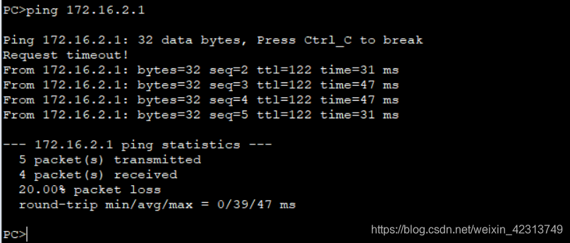
- ping
这里我发现已经ping 通,进过抓包和查看路由表发现,公网并没有路由。
[R5]dis ip routing-table protocol ospf
Route Flags: R - relay, D - download to fib
------------------------------------------------------------------------------
Public routing table : OSPF
         Destinations : 5        Routes : 5

OSPF routing table status : <Active>
         Destinations : 5        Routes : 5

Destination/Mask    Proto   Pre  Cost      Flags NextHop         Interface

        2.2.2.2/32  OSPF    10   3           D   10.1.45.4       GigabitEthernet
0/0/0
        3.3.3.3/32  OSPF    10   2           D   10.1.45.4       GigabitEthernet
0/0/0
        4.4.4.4/32  OSPF    10   1           D   10.1.45.4       GigabitEthernet
0/0/0
      10.1.23.0/24  OSPF    10   3           D   10.1.45.4       GigabitEthernet
0/0/0
      10.1.34.0/24  OSPF    10   2           D   10.1.45.4       GigabitEthernet
0/0/0

OSPF routing table status : <Inactive>
         Destinations : 0        Routes : 0

[R5]
故障诊断
控制层:
- CE是否发布路由给PE
- PE是否发布路由给PE
- PE间是否建立MP-IBGP
- PE之间是否建立LSP
数据平面
- MTU值
总结
- 实验配置总结:
- 底层一定要通
- PE 要做双向引入
- 绑定实例时,接口地址会移除,需要丛培


 2338
2338


 被折叠的 条评论
为什么被折叠?
被折叠的 条评论
为什么被折叠?
 到【灌水乐园】发言


