


目录
常用命令
# 开机快速清空网络设备
reset saved-configuration
reboot
show running-config // 查看路由器运行配置
VLAN 原理与配置
VLAN 工作原理
802.1Q 帧
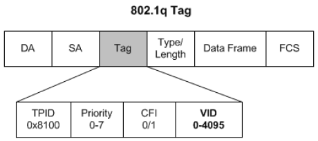
- 在标准以太网帧头部增加 TAG 字段
- 标记协议标识(TPID): 固定值 0x8100,表示该帧载有 802.1Q 标记信息
- 标记控制信息(TCI):
- VLAN ID:12 比特,表示 VID,可用范围 1-4094
- Priority:3 比特,表示优先级
- Canonical format indicator:1 比特,表示总线型以太网、FDDI、令牌环网
端口类型
- 交换机的两种端口类型
- Access: 一般用于连接用户终端,承载标准的以太网帧,只能关联一个 VLAN
- Trunk: 一般用于交换机互联,承载 802.1Q 帧 ,缺省关联交换机上配置的所有 VLAN

VLAN 配置
- 创建 VLAN
Switch(config)#为命令行的提示符vlan为命令名vlan-id为想要创建的 VLAN 的 ID
Switch(config)# vlan vlan-id
- 命名 VLAN
Switch(config-vlan)# name vlan-name
- 配置 Access 口
步骤1:进入端口配置模式
Swtich(config)# interface interface
Swtich(config)# interface range interface-range	// 也可以同时配置多个端口

步骤2:将端口模式设置为接入端口 (可选)
Switch(config-if)# switchport mode access

步骤3:将端口添加到特定VLAN
Switch(config-if)# switchport access vlan vlan-id
- 配置 Trunk
步骤1:进入端口配置模式
Swtich(config)# interface interface

步骤2:将端口模式设置为Trunk
Switch(config-if)# switchport mode trunk

步骤2:定义Trunk的VLAN列表
Switch(config-if)# switchport trunk allowed vlan { all | [add | remove | except ]} vlan-list
// 配置为 Trunk 端口,但是不包含 VLAN2
Switch(config-if)# switchport trunk allowed vlan remove 2
- 查看 / 删除 VLAN
Swtich(config)# no vlan VLAN-id
- 验证配置信息
Swtich# show interfaces fastethernet0/20 switchport
Swtich# show vlan
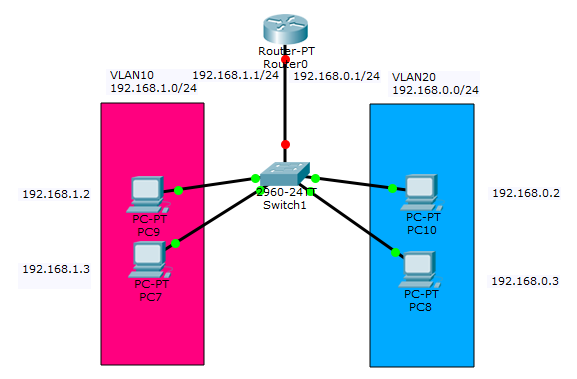
网络拓扑
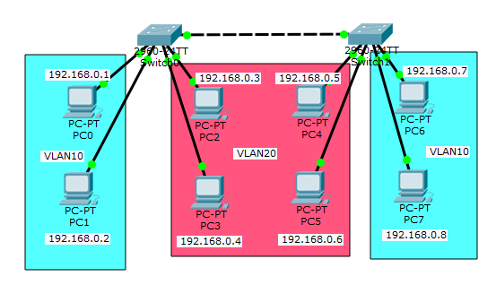
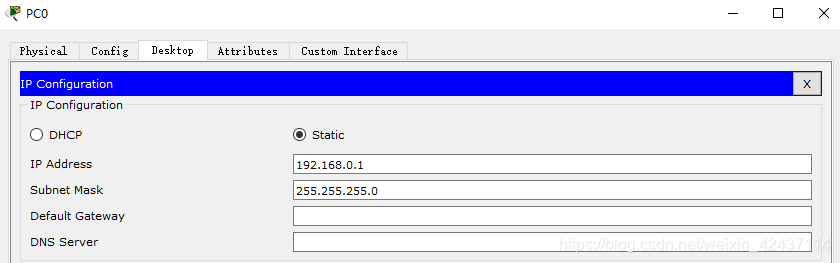
配置端系统的 IP 地址以及子网掩码
配置交换机 (下面是 Switch0 的配置,Switch1 的配置同理)
Switch> en		// 进入特权模式
Switch# configure terminal // 进入配置模式
Enter configuration commands, one per line.  End with CNTL/Z.

Switch(config)# vlan 10		// 添加 VLAN
Switch(config-vlan)# name VLAN-10
Switch(config-vlan)# vlan 20
Switch(config-vlan)# name VLAN-20
Switch(config-vlan)# end

Switch# show vlan	// 查看 VLAN 配置情况

VLAN Name                             Status    Ports
...
10   VLAN-10                          active
20   VLAN-20                          active
...

Switch# configure terminal
Enter configuration commands, one per line.  End with CNTL/Z.

Switch(config)# interface range f0/1-2	// 配置 access 接口
Switch(config-if-range)# switchport access vlan 10
Switch(config-if-range)#exit
Switch(config)#interface range f0/3-4
Switch(config-if-range)#switchport access vlan 20
Switch(config-if-range)#exit

Switch(config)#interface f0/5	// 配置 trunk 口
Switch(config-if)#switchport mode trunk
结果检验
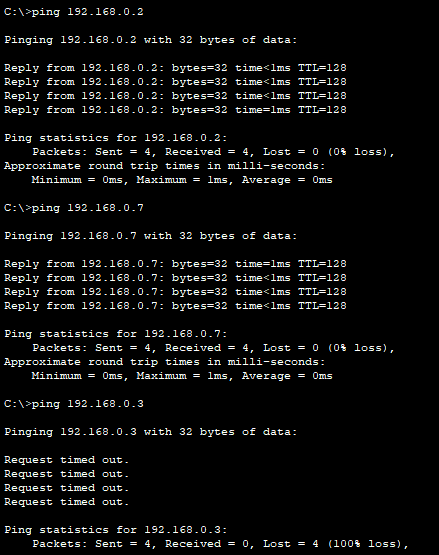
- 如下图所示,PC0 可以
ping通 PC1 和 PC6,但ping不通 PC2
路由原理与静态路由
- 静态路由配置命令
- 例:
ip route 192.168.10.0 255.255.255.0 172.16.2.1 - 例:
ip route 192.168.10.0 255.255.255.0 serial 1
- 例:
RSR(config)# ip route [网络号] [子网掩码] [下一跳路由器的IP地址/本地接口]
- 配置默认路由
router(config)# ip route 0.0.0.0 0.0.0.0 [转发路由器的IP地址/本地接口]
- 查看路由表
RSR# show ip route
单臂路由配置
参考:单臂路由的详解及简单配置
- VLAN 能有效分割局域网,实现各网络区域之间的访问控制。但现实中,往往需要配置某些 VLAN 之间的互联互通
- 单臂路由(router-on-a-stick)是指在路由器的一个接口上通过配置子接口(或“逻辑接口”,并不存在真正物理接口)的方式,实现原来相互隔离的不同 VLAN 之间的互联互通
- 逻辑子接口: 路由器的物理接口可以被划分成多个逻辑接口,这些被划分后的逻辑接口被形象的称为子接口。值得注意的是这些逻辑子接口不能被单独的开启或关闭,也就是说,当物理接口被开启或关闭时,所有的该接口的子接口也随之被开启或关闭
- 子接口封装协议是 802.1Q 并指定对应的 VLAN,每个子接口配置 IP 地址作为网关
网络拓扑图
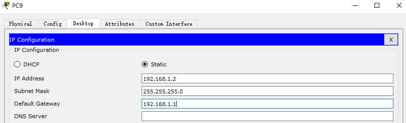
配置端设备的 IP 地址、子网掩码以及网关
- 以 PC9 为例,设置它的 IP 地址和子网掩码,并将路由器的一个逻辑子接口作为它的默认网关
配置交换机
Switch> en
Switch# conf t
Enter configuration commands, one per line. End with CNTL/Z.

Switch(config)# vlan 10  // 创建vlan10端口和vlan20端口
Switch(config-vlan)# name VLAN10
Switch(config-vlan)# vlan 20
Switch(config-vlan)# name VLAN20
Switch(config-vlan)# exit

Switch(config)# interface range f0/1-2  // 划分1-2为vlan10,3-4为vlan20
Switch(config-if-range)# switchport access vlan 10

Switch(config-if-range)# interface range f0/3-4
Switch(config-if-range)# switchport access vlan 20
Switch(config-if-range)# exit

Switch(config)# interface f0/5 // 设置连接路由器的接口为Trunk类型
Switch(config-if)# switchport mode trunk
Switch# show vlan

VLAN Name                             Status    Ports
...
10   VLAN10                           active    Fa0/1, Fa0/2
20   VLAN20                           active    Fa0/3, Fa0/4
配置路由器
Router> en			// 进入特权模式
Router# conf t		// 进入配置模式
Enter configuration commands, one per line. End with CNTL/Z.

Router(config)# interface f0/0.1  				// 创建 f0/0.1 逻辑子接口 (属于物理接口 f0/0)
Router(config-subif)# encapsulation dot1q 10 	// 设置该逻辑子接口接收 802.1Q 帧, 并指定接口所属 VLAN
Router(config-subif)# ip address 192.168.1.1 255.255.255.0 // 设置逻辑子接口IP地址和地址掩码

Router(config-subif)# interface f0/0.2
Router(config-subif)# encapsulation dot1q 20
Router(config-subif)# ip address 192.168.0.1 255.255.255.0 // 为子接口设置 IP 地址,作为对应 VLAN 内主机的网关

Router(config-subif)# interface f0/0  // 开启f0/0接口和子接口
Router(config-if)# no shutdown
- 用 PC9
pingPC10,第一次ping时,第一个 ICMP 数据包超时,其他数据包正常发送。这是因为交换机在转发数据帧的时候,最开始不知道目的主机的 IP 地址,于是只能进行 ARP 广播请求,而不是ping请求,这一次的ping数据帧就被扔掉了,当知道了具体主机的 IP 地址后,之后就可以准确送达
C:\>ping 192.168.0.2

Pinging 192.168.0.2 with 32 bytes of data:

Request timed out.
Reply from 192.168.0.2: bytes=32 time<1ms TTL=127
Reply from 192.168.0.2: bytes=32 time<1ms TTL=127
Reply from 192.168.0.2: bytes=32 time<1ms TTL=127

Ping statistics for 192.168.0.2:
    Packets: Sent = 4, Received = 3, Lost = 1 (25% loss),
Approximate round trip times in milli-seconds:
    Minimum = 0ms, Maximum = 0ms, Average = 0ms

C:\>ping 192.168.0.2

Pinging 192.168.0.2 with 32 bytes of data:

Reply from 192.168.0.2: bytes=32 time<1ms TTL=127
Reply from 192.168.0.2: bytes=32 time<1ms TTL=127
Reply from 192.168.0.2: bytes=32 time=3ms TTL=127
Reply from 192.168.0.2: bytes=32 time=27ms TTL=127

Ping statistics for 192.168.0.2:
    Packets: Sent = 4, Received = 4, Lost = 0 (0% loss),
Approximate round trip times in milli-seconds:
    Minimum = 0ms, Maximum = 27ms, Average = 7ms
静态路由配置
- 在上一部分的基础上,增加一台路由器和交换机,通过手工配置路由使数据报按照预定路径传送到指定目标网络
- VLAN 10 可以和 VLAN 30 互通,但 VLAN 20 不能和 VLAN 30 互通
网络拓扑
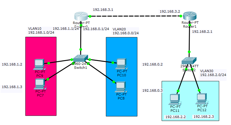
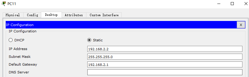
配置端设备 PC11, PC12 的 IP 地址、子网掩码、网关
配置交换机
Switch>en
Switch# conf t
Enter configuration commands, one per line.  End with CNTL/Z.

Switch(config)# vlan 30
Switch(config-vlan)# name VLAN30
Switch(config-vlan)# exit

Switch(config)# interface f0/2
Switch(config-if)#switchport access vlan 30
Switch(config-if)#exit
Switch(config)# interface f0/3
Switch(config-if)#switchport access vlan 30
Switch(config-if)#exit

Switch(config)#interface f0/1
Switch(config-if)#switchport mode trunk
Switch(config-if)#end

Switch# show vlan

VLAN Name                             Status    Ports
...
30   VLAN30                           active    Fa0/2
...
配置路由器
// 配置 R0
Router(config)# interface f1/0
Router(config-if)# no shutdown
Router(config-if)# ip address 192.168.3.1 255.255.255.0
Router(config-if)# exit
Router(config)# ip route 192.168.2.0 255.255.255.0 192.168.3.2	// 设置静态路由
// 显示 R0 路由表
Router# show ip route
Codes: C - connected, S - static, I - IGRP, R - RIP, M - mobile, B - BGP
       D - EIGRP, EX - EIGRP external, O - OSPF, IA - OSPF inter area
       N1 - OSPF NSSA external type 1, N2 - OSPF NSSA external type 2
       E1 - OSPF external type 1, E2 - OSPF external type 2, E - EGP
       i - IS-IS, L1 - IS-IS level-1, L2 - IS-IS level-2, ia - IS-IS inter area
       * - candidate default, U - per-user static route, o - ODR
       P - periodic downloaded static route

Gateway of last resort is not set

C    192.168.0.0/24 is directly connected, FastEthernet0/0.2
C    192.168.1.0/24 is directly connected, FastEthernet0/0.1
S    192.168.2.0/24 [1/0] via 192.168.3.2
C    192.168.3.0/24 is directly connected, FastEthernet1/0
Router> en
Router# conf t
Enter configuration commands, one per line.  End with CNTL/Z.

Router(config)# interface f0/0
Router(config-if)# ip address 192.168.3.2 255.255.255.0
Router(config-if)# no shutdown
Router(config-if)# exit
Router(config)# ip route 192.168.1.0 255.255.255.0 192.168.3.1

Router(config)# interface f1/0
Router(config-if)# no shutdown

Router(config-if)# interface f1/0.1
Router(config-subif)# encapsulation dot1Q 30
Router(config-subif)# ip address 192.168.2.1 255.255.255.0
Router(config-subif)# end
Router# show ip route
Codes: C - connected, S - static, I - IGRP, R - RIP, M - mobile, B - BGP
       D - EIGRP, EX - EIGRP external, O - OSPF, IA - OSPF inter area
       N1 - OSPF NSSA external type 1, N2 - OSPF NSSA external type 2
       E1 - OSPF external type 1, E2 - OSPF external type 2, E - EGP
       i - IS-IS, L1 - IS-IS level-1, L2 - IS-IS level-2, ia - IS-IS inter area
       * - candidate default, U - per-user static route, o - ODR
       P - periodic downloaded static route

Gateway of last resort is not set

S    192.168.1.0/24 [1/0] via 192.168.3.1
C    192.168.2.0/24 is directly connected, FastEthernet1/0.1
C    192.168.3.0/24 is directly connected, FastEthernet0/0
结果验证
- 用 PC11
pingPC9 可以ping通;用 PC11pingPC10 不可以ping通,达到效果
C:\>ping 192.168.1.2

Pinging 192.168.1.2 with 32 bytes of data:

Reply from 192.168.1.2: bytes=32 time=5ms TTL=126
Reply from 192.168.1.2: bytes=32 time<1ms TTL=126
Reply from 192.168.1.2: bytes=32 time<1ms TTL=126
Reply from 192.168.1.2: bytes=32 time<1ms TTL=126

Ping statistics for 192.168.1.2:
    Packets: Sent = 4, Received = 4, Lost = 0 (0% loss),
Approximate round trip times in milli-seconds:
    Minimum = 0ms, Maximum = 5ms, Average = 1ms

C:\>ping 192.168.0.2

Pinging 192.168.0.2 with 32 bytes of data:

Reply from 192.168.2.1: Destination host unreachable.
Reply from 192.168.2.1: Destination host unreachable.
Reply from 192.168.2.1: Destination host unreachable.
Reply from 192.168.2.1: Destination host unreachable.

Ping statistics for 192.168.0.2:
    Packets: Sent = 4, Received = 0, Lost = 4 (100% loss),
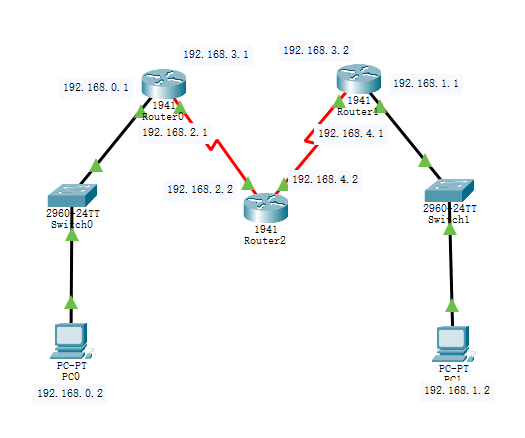
OSPF 动态路由配置
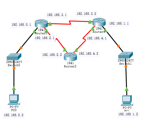
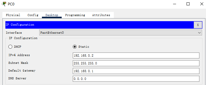
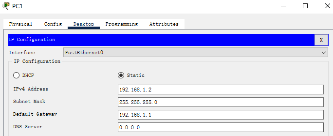
- 首先配置 PC0 和 PC1 的 IP 地址、子网掩码以及网关
- 设置路由器接口 IP 地址并设置使用 RIP 路由选择算法 (下面以 Router 0 为例,其他路由器的设置同理)
Router>enable
Router#configure terminal
Enter configuration commands, one per line.  End with CNTL/Z.

Router(config)#interface gigabitEthernet 0/0
Router(config-if)#ip address 192.168.0.1 255.255.255.0
Router(config-if)#no shutdown
Router(config-if)#exit

Router(config)#interface serial 0/0/1
Router(config-if)#ip address 192.168.2.1 255.255.255.0
Router(config-if)#no shutdown
Router(config-if)#exit

Router(config)#interface serial 0/0/0
Router(config-if)#ip address 192.168.3.1 255.255.255.0
Router(config-if)#no shutdown

Router(config)#router ospf 1	// Enables OSPF routing and enters router configuration mode.
Router(config-router)#network 192.168.0.0 0.0.0.255 area 0	// Defines an interface on which OSPF runs and defines the area ID for that interface.
Router(config-router)#network 192.168.3.0 0.0.0.255 area 0
Router(config-router)#network 192.168.2.0 0.0.0.255 area 0
Router(config-router)#end
- 当三个路由器配置完成后,查看路由表发现相关路由表项已经被自动填入了路由表
- 下面以 Router0 的路由表为例, 可以看到,到达
192.168.1.0的下一跳地址为192.168.3.2,也就是 Router1。它的确选择的是最短路径
- 下面以 Router0 的路由表为例, 可以看到,到达
// Router 0
Router#show ip route
Codes: L - local, C - connected, S - static, R - RIP, M - mobile, B - BGP
       D - EIGRP, EX - EIGRP external, O - OSPF, IA - OSPF inter area
       N1 - OSPF NSSA external type 1, N2 - OSPF NSSA external type 2
       E1 - OSPF external type 1, E2 - OSPF external type 2, E - EGP
       i - IS-IS, L1 - IS-IS level-1, L2 - IS-IS level-2, ia - IS-IS inter area
       * - candidate default, U - per-user static route, o - ODR
       P - periodic downloaded static route

Gateway of last resort is not set

     192.168.0.0/24 is variably subnetted, 2 subnets, 2 masks
C       192.168.0.0/24 is directly connected, GigabitEthernet0/0
L       192.168.0.1/32 is directly connected, GigabitEthernet0/0
O    192.168.1.0/24 [110/65] via 192.168.3.2, 00:00:19, Serial0/0/0
     192.168.2.0/24 is variably subnetted, 2 subnets, 2 masks
C       192.168.2.0/24 is directly connected, Serial0/0/1
L       192.168.2.1/32 is directly connected, Serial0/0/1
     192.168.3.0/24 is variably subnetted, 2 subnets, 2 masks
C       192.168.3.0/24 is directly connected, Serial0/0/0
L       192.168.3.1/32 is directly connected, Serial0/0/0
O    192.168.4.0/24 [110/128] via 192.168.3.2, 00:00:19, Serial0/0/0
                    [110/128] via 192.168.2.2, 00:00:19, Serial0/0/1
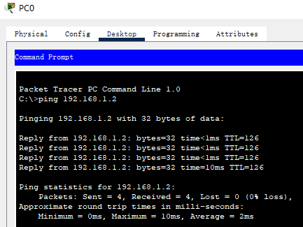
- 用 PC0
pingPC1 发现ping通,说明实验成功

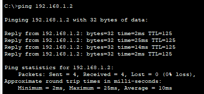
- 下面测试 OSPF 的动态性,删掉 Router0 和 Router1 之间的串口线,即刚才 Router 0 到
192.168.1.0/24网络走的路线。可以看到,Router0 到192.168.1.0/24网络的下一跳路线变成了192.168.2.2,即 Router2;PC0 仍然可以ping通192.168.1.2
// Router 0
Router#show ip route
Codes: L - local, C - connected, S - static, R - RIP, M - mobile, B - BGP
       D - EIGRP, EX - EIGRP external, O - OSPF, IA - OSPF inter area
       N1 - OSPF NSSA external type 1, N2 - OSPF NSSA external type 2
       E1 - OSPF external type 1, E2 - OSPF external type 2, E - EGP
       i - IS-IS, L1 - IS-IS level-1, L2 - IS-IS level-2, ia - IS-IS inter area
       * - candidate default, U - per-user static route, o - ODR
       P - periodic downloaded static route

Gateway of last resort is not set

     192.168.0.0/24 is variably subnetted, 2 subnets, 2 masks
C       192.168.0.0/24 is directly connected, GigabitEthernet0/0
L       192.168.0.1/32 is directly connected, GigabitEthernet0/0
O    192.168.1.0/24 [110/129] via 192.168.2.2, 00:00:05, Serial0/0/1
     192.168.2.0/24 is variably subnetted, 2 subnets, 2 masks
C       192.168.2.0/24 is directly connected, Serial0/0/1
L       192.168.2.1/32 is directly connected, Serial0/0/1
O    192.168.4.0/24 [110/128] via 192.168.2.2, 00:00:05, Serial0/0/1
RIP 路由协议配置
- 首先配置 PC0 和 PC1 的 IP 地址、子网掩码以及网关
- 设置路由器接口 IP 地址并设置使用 RIP 路由选择算法 (下面以 Router 0 为例,其他路由器的设置同理)
Router>enable
Router#configure terminal
Enter configuration commands, one per line.  End with CNTL/Z.

Router(config)#interface gigabitEthernet 0/0
Router(config-if)#ip address 192.168.0.1 255.255.255.0
Router(config-if)#no shutdown
Router(config-if)#exit

Router(config)#interface serial 0/0/1
Router(config-if)#ip address 192.168.2.1 255.255.255.0
Router(config-if)#no shutdown
Router(config-if)#exit

Router(config)#interface serial 0/0/0
Router(config-if)#ip address 192.168.3.1 255.255.255.0
Router(config-if)#no shutdown

Router(config)#router rip
Router(config-router)#network 192.168.0.0
Router(config-router)#network 192.168.2.0
Router(config-router)#network 192.168.3.0
Router(config-router)#version 2
Router(config-router)#end
- 当三个路由器配置完成后,查看路由表发现相关路由表项已经被自动填入了路由表
- 下面以 Router0 的路由表为例, 可以看到,到达
192.168.1.0的下一跳地址为192.168.3.2,也就是 Router1。它的确选择的是最短路径
- 下面以 Router0 的路由表为例, 可以看到,到达
// Router 0
Router#show ip route
Codes: L - local, C - connected, S - static, R - RIP, M - mobile, B - BGP
       D - EIGRP, EX - EIGRP external, O - OSPF, IA - OSPF inter area
       N1 - OSPF NSSA external type 1, N2 - OSPF NSSA external type 2
       E1 - OSPF external type 1, E2 - OSPF external type 2, E - EGP
       i - IS-IS, L1 - IS-IS level-1, L2 - IS-IS level-2, ia - IS-IS inter area
       * - candidate default, U - per-user static route, o - ODR
       P - periodic downloaded static route

Gateway of last resort is not set

     192.168.0.0/24 is variably subnetted, 2 subnets, 2 masks
C       192.168.0.0/24 is directly connected, GigabitEthernet0/0
L       192.168.0.1/32 is directly connected, GigabitEthernet0/0
R    192.168.1.0/24 [120/1] via 192.168.3.2, 00:00:18, Serial0/0/0
     192.168.2.0/24 is variably subnetted, 2 subnets, 2 masks
C       192.168.2.0/24 is directly connected, Serial0/0/1
L       192.168.2.1/32 is directly connected, Serial0/0/1
     192.168.3.0/24 is variably subnetted, 2 subnets, 2 masks
C       192.168.3.0/24 is directly connected, Serial0/0/0
L       192.168.3.1/32 is directly connected, Serial0/0/0
R    192.168.4.0/24 [120/1] via 192.168.2.2, 00:00:13, Serial0/0/1
                    [120/1] via 192.168.3.2, 00:00:18, Serial0/0/0
- 用 PC0
pingPC1 发现ping通,说明实验成功
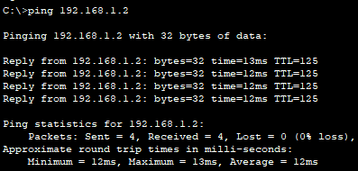
- 下面测试 RIP 的动态性,删掉 Router0 和 Router1 之间的串口线,即刚才 Router 0 到
192.168.1.0/24网络走的路线。可以看到,Router0 到192.168.1.0/24网络的下一跳路线变成了192.168.2.2,即 Router2;PC0 仍然可以ping通192.168.1.2
// Router 0
Router#show ip route
Codes: L - local, C - connected, S - static, R - RIP, M - mobile, B - BGP
       D - EIGRP, EX - EIGRP external, O - OSPF, IA - OSPF inter area
       N1 - OSPF NSSA external type 1, N2 - OSPF NSSA external type 2
       E1 - OSPF external type 1, E2 - OSPF external type 2, E - EGP
       i - IS-IS, L1 - IS-IS level-1, L2 - IS-IS level-2, ia - IS-IS inter area
       * - candidate default, U - per-user static route, o - ODR
       P - periodic downloaded static route

Gateway of last resort is not set

     192.168.0.0/24 is variably subnetted, 2 subnets, 2 masks
C       192.168.0.0/24 is directly connected, GigabitEthernet0/0
L       192.168.0.1/32 is directly connected, GigabitEthernet0/0
R    192.168.1.0/24 [120/2] via 192.168.2.2, 00:00:05, Serial0/0/1
     192.168.2.0/24 is variably subnetted, 2 subnets, 2 masks
C       192.168.2.0/24 is directly connected, Serial0/0/1
L       192.168.2.1/32 is directly connected, Serial0/0/1
R    192.168.4.0/24 [120/1] via 192.168.2.2, 00:00:05, Serial0/0/1
IPv4 与 IPv6 协议互通
- 要求完成不同 VLAN 下, IPv4 协议下局域网设备与 IPv6 协议下局域网终端之间的互通
# 查看配置情况
Router# show ipv6 interface
Router# show ipv6 interface brief
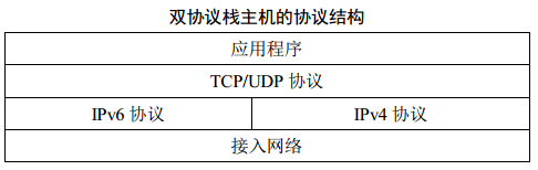
双栈技术
6to4 隧道
- 6to4 隧道 使用的 IPv6 地址有固定的格式:
- 地址前缀为
2002::开头,固定2002:后面拼接全球 IPv4 单播地址 (32 位),形成 48 位前缀,最后 64 位拼接任意方式形成的主机标识
- 地址前缀为
ISATAP 隧道
Intra-site (internal site) Automatic Tunnel Address Protocol
ISATAP 隧道
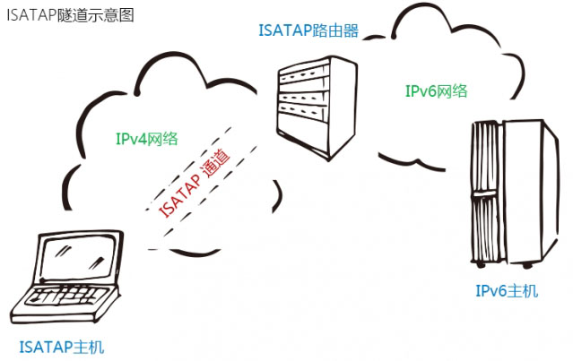
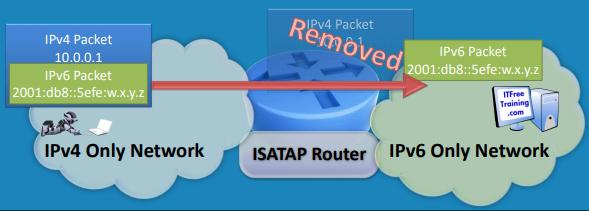
- 在一个 IPv4 网络中,主机与 ISATAP 路由器之间创建一条使用 IPv6 地址的 ISATAP 隧道 (IPv6 数据报被封装在 IPv4 数据报中)。如此一来,这台 PC 就能够通过 ISATAP 路由器访问 IPv6 资源。同理,IPv6 主机也能通过 ISATAP 路由器来访问 ISATAP 主机,从而实现了 IPv4 协议下局域网设备与 IPv6 协议下局域网终端之间的互通
- 条件:IPv4 中的 PC 主机需要支持 IPv4 和 IPv6 双栈协议,然后需要一台支持 ISATAP 的路由器。该路由器可以在网络中的任何位置,只要 PC 能通过 IPv4 地址
ping通它
ISATAP 隧道原理详解
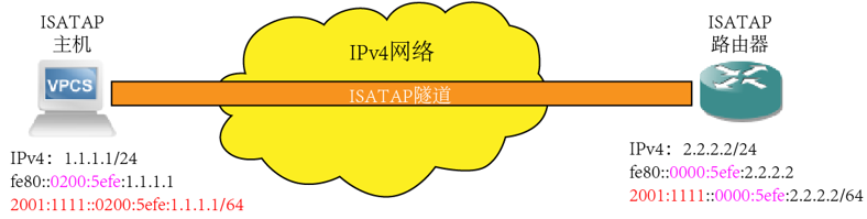
- ISATAP 路由器配置:
- (1) 分配 IPv4 地址:
2.2.2.2/24。该地址用于在 IPv4 网络中与 ISATAP 主机通信 - (2) 创建 tunnel 接口用于 ISATAP,该接口会根据 IPv4 地址产生一个 64 位的接口标识,并搭配
fe80::形成 tunnel 接口的 LinkLocal 地址,格式 :fe80::0000:5efe:x.x.x.x(其中的0000:5efe表明这是一个 IPv6 ISATAP 地址;x.x.x.x为 IPv4 地址) - (3) 为 tunnel 接口配置一个全局单播 IPv6 地址,可以手工配置,也可以通过 +EUI64 的方式构成。这个 IPv6 地址是用来访问外部 IPv6 网络的
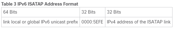
- ISATAP uses a well-defined IPv6 address format composed of any unicast IPv6 prefix (/64), which can be link local, or global (including 6to4 prefixes), enabling IPv6 routing locally or on the Internet. The IPv4 address is encoded in the last 32 bits of the IPv6 address, enabling automatic IPv6-in-IPv4 tunneling.
- The ISATAP router provides standard router advertisement network configuration support for the ISATAP site. This feature allows clients to automatically configure themselves as they would do if they were connected to a GigabitEthernet or FastEthernet. It can also be configured to provide connectivity out of the site.
- ISATAP uses a well-defined IPv6 address format composed of any unicast IPv6 prefix (/64), which can be link local, or global (including 6to4 prefixes), enabling IPv6 routing locally or on the Internet. The IPv4 address is encoded in the last 32 bits of the IPv6 address, enabling automatic IPv6-in-IPv4 tunneling.
- (1) 分配 IPv4 地址:
地址后面的 64 bit (
0000:5EFE:x.y.z.w) 称为 interface ID
- ISATAP 主机配置:
- (1) ISATAP 主机配置的主要任务就是向 ISATAP 路由器获取它的 IPv6 地址。Win7 系统上默认安装了 IPv6 协议栈,默认就会有一个 ISATAP 的虚拟网卡。当给 PC 的物理网卡配置 IPv4 地址(如
1.1.1.1/24) 时,ISATAP 虚拟网卡会自动根据该地址计算出一个 LinkLocal 地址,格式如:fe80::0000:5efe:1.1.1.1 - (2) 当主机上配置 ISATAP 后(用
netsh命令,使其指向 ISATAP 路由器),向 ISATAP 路由器发送 RS 消息请求 IPv6 前缀 (注意:IPv4 数据报中封装的 IPv6 数据报的源地址和目的地址分别为 ISATAP 主机和 ISATAP 路由器的 link local 地址 (下图中0200应为0000))

- (3) 这个 RS 消息会在 IPv4 网络中被路由,最终转到 ISATAP 路由器。这将使得路由器立即以一个 RA (Router Advertisement) 进行回应,这个 RA 消息里就包含 ISATAP 上所配置的那个 IPv6 全局单播地址的前缀
- (4) PC 主机收到 RA 回应后,会拿出里头的 IPv6 前缀,随后在后面加上自己的 ISATAP 虚拟网卡的 64 位接口标识地址,构成一个 IPv6 全局单播地址,并被自动关联到 ISATAP 虚拟网卡上,同时产生一条默认路由,指向 ISATAP 路由器的 LinkLocal 地址
- (1) ISATAP 主机配置的主要任务就是向 ISATAP 路由器获取它的 IPv6 地址。Win7 系统上默认安装了 IPv6 协议栈,默认就会有一个 ISATAP 的虚拟网卡。当给 PC 的物理网卡配置 IPv4 地址(如
- 至此,PC 主机就可以访问 IPv6 网络中的资源。它首先将 IPv6 数据包封装在 IPv4 数据包中,然后传给 ISATAP 路由器,再由 ISATAP 路由器解封装后转发给 IPv6 网络

配置 IPv4 网络
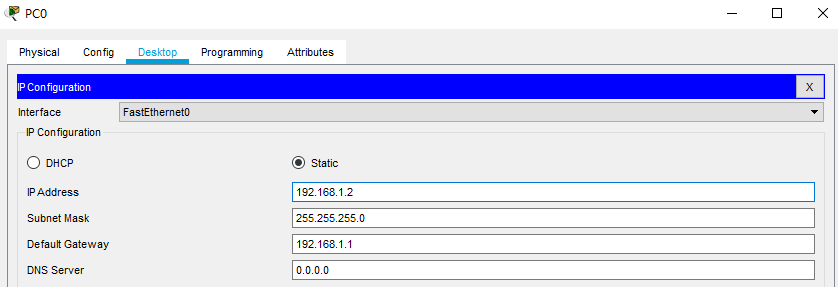
- 配置 PC2 的 IP 地址、子网掩码和网关
- 配置交换机 (添加 VLAN、设置 Access 和 Trunk 接口)
// Switch0
Switch>enable
Switch#configure terminal
Enter configuration commands, one per line.  End with CNTL/Z.

Switch(config)#vlan 10
Switch(config-vlan)#name VLAN-10
Switch(config-vlan)#exit

Switch(config)#interface fastEthernet 0/1
Switch(config-if)#switchport access vlan 10
Switch(config-if)#exit

Switch(config)#interface fastEthernet 0/2
Switch(config-if)#switchport mode trunk
Switch(config-if)#end
- 配置路由器
// Router 0
Router>enable
Router#configure terminal
Enter configuration commands, one per line.  End with CNTL/Z.

Router(config)#interface gigabitEthernet 0/0/0
Router(config-if)#no shutdown
Router(config)#exit

Router(config)#interface gigabitEthernet 0/0/0.1
Router(config-subif)#encapsulation dot1Q 10
Router(config-subif)#ip address 192.168.1.1 255.255.255.0
Router(config-subif)#exit

Router(config)#interface gigabitEthernet 0/0/1
Router(config-if)#no shutdown
Router(config-if)#ip address 192.168.2.1 255.255.255.0
Router(config-if)#end
配置 IPv6 网络
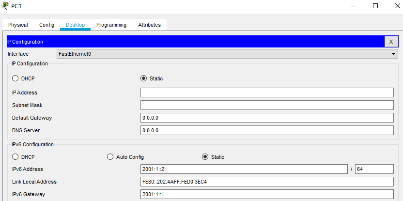
- 配置 PC1 的 IPV6 地址、网络掩码和默认网关
- 配置交换机
// Switch1
Switch>enable
Switch#configure terminal
Enter configuration commands, one per line.  End with CNTL/Z.

Switch(config)#vlan 20
Switch(config-vlan)#name VLAN-20
Switch(config-vlan)#exit

Switch(config)#interface fastEthernet 0/2
Switch(config-if)#switchport access vlan 20
Switch(config-if)#exit

Switch(config)#interface fastEthernet 0/1
Switch(config-if)#switchport mode trunk
Switch(config-if)#end
- 配置路由器
// Router2
Router#enable
Router#configure terminal
Enter configuration commands, one per line.  End with CNTL/Z.

Router(config)#ipv6 unicast-routing

Router(config)#interface gigabitEthernet 0/0/0
Router(config-if)#ipv6 address 2001:2::2/64
Router(config-if)#no shutdown
Router(config-if)#exit

Router(config)#interface gigabitEthernet 0/0/1
Router(config-if)#no shutdown
Router(config-if)#exit

Router(config)#interface gigabitEthernet 0/0/1.1
Router(config-subif)#encapsulation dot1Q 20
Router(config-subif)#ipv6 address 2001:1::1/64
Router(config-subif)#end
ISATAP隧道配置
// Router 1
Router> enable
Router# configure terminal
Enter configuration commands, one per line.  End with CNTL/Z.

Router(config)#interface gigabitEthernet 0/0/0
Router(config-if)#ip address 192.168.2.2 255.255.255.0
Router(config-if)#no shutdown
Router(config-if)#exit

Router(config)#interface gigabitEthernet 0/0/1
Router(config-if)#ipv6 address 2001:2::1/64
Router(config-if)#no shutdown
Router(config-if)#exit

Router(config)#ipv6 unicast-routing
Router(config)#ip route 192.168.1.0 255.255.255.0 192.168.2.1
Router(config)#ipv6 route 2001:1::/64 2001:2::2

Router(config)#interface tunnel 0					// Specifies a tunnel interface and number, and enters interface configuration mode.
Router(config-if)#ipv6 address 2001:3::/64 eui-64	// Specifies the IPv6 address assigned to the interface and enables IPv6 processing on the interface
Router(config-if)#no ipv6 nd ra suppress 			// Reenable the sending of IPv6 router advertisements to allow client auto configuration
Router(config-if)#tunnel source gigabitEthernet 0/0/0	// Specifies the source interface type and number for the tunnel interface.
Router(config-if)#tunnel mode ipv6ip isatap
Router(config-if)#no shutdown
Router(config-if)#exit
// Router2
Router(config)# ipv6 route 2001:3::/64 2001:2::1	// 设置完隧道后,IPv4 网络中使用隧道的主机使用的 IPv6 地址即为 2001:3::x.y.z.w,因此 R3 需要增设路由项
配置 ISATAP 主机
注:每次重新打开
.pkt文件都需要重新进行配置 ISATAP 主机的操作
// 可以发现 ISATAP 路由器
C:\>netsh interface ipv6 show potentialrouters

Idx  Router Address
---  ------------------------
2     FE80::5EFE:C0A8:202

// 向 ISATAP 路由器发送 RS 消息,请求 IPv6 全局单播地址的前缀
C:\>netsh interface isatap set router 192.168.2.2
Ok.

// 使能 isatap
C:\>netsh interface isatap set state enabled
Ok.
测试
注:如果以上配置都正确无误但模拟测试仍不成功,可以关掉 Cisco 模拟器再打开一下,然后重复配置 ISATAP 主机的操作就行了。我就是在这边卡了好久
- 查看 ISATAP 主机的 ISATAP 虚拟网卡配置
C:\>ipconfig

FastEthernet0 Connection:(default port)

   Connection-specific DNS Suffix..:
   Link-local IPv6 Address.........: FE80::210:11FF:FE0C:558E
   IPv6 Address....................: ::
   IPv4 Address....................: 192.168.1.2
   Subnet Mask.....................: 255.255.255.0
   Default Gateway.................: FE80::5EFE:C0A8:202
                                     192.168.1.1

Bluetooth Connection:

   Connection-specific DNS Suffix..:
   Link-local IPv6 Address.........: ::
   IPv6 Address....................: ::
   IPv4 Address....................: 0.0.0.0
   Subnet Mask.....................: 0.0.0.0
   Default Gateway.................: ::
                                     0.0.0.0

IsatapTunnel0 Connection:									// ISATAP 虚拟网卡
 --More--
   Connection-specific DNS Suffix..:
   Link-local IPv6 Address.........: FE80::5EFE:C0A8:102	// Link local 地址,后 32 位为 IPv4 地址
   IPv6 Address....................: 2001:3::C0A8:102		// 获取的 IPv6 前缀加上自己的 IPv4 地址
   IPv4 Address....................: 0.0.0.0
   Subnet Mask.....................: 0.0.0.0
   Default Gateway.................: FE80::5EFE:C0A8:202	// 默认网关被自动设置为 ISATAP 路由器的 link local 地址
                                     0.0.0.0

IsatapTunnel1 Connection:

   Connection-specific DNS Suffix..:
   Link-local IPv6 Address.........: FE80::200:5EFE:0:0
   IPv6 Address....................: ::
   IPv4 Address....................: 0.0.0.0
   Subnet Mask.....................: 0.0.0.0
   Default Gateway.................: ::
                                     0.0.0.0
- IPv4主机 (ISATAP 主机)
pingIPv6主机
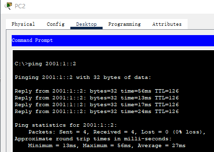
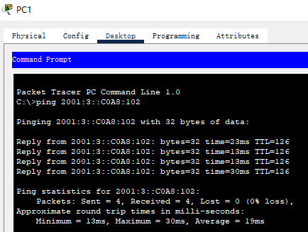
- IPv6 主机
pingIPv4 主机 (ISATAP 主机). 注意这里不是直接pingIPv4 地址,而是pingISATAP 主机对应的 IPv6 地址2001:3::C0A8:102,其中最后 32 位C0A8:102对应 ISATAP 主机的 IPv4 地址192.168.1.2
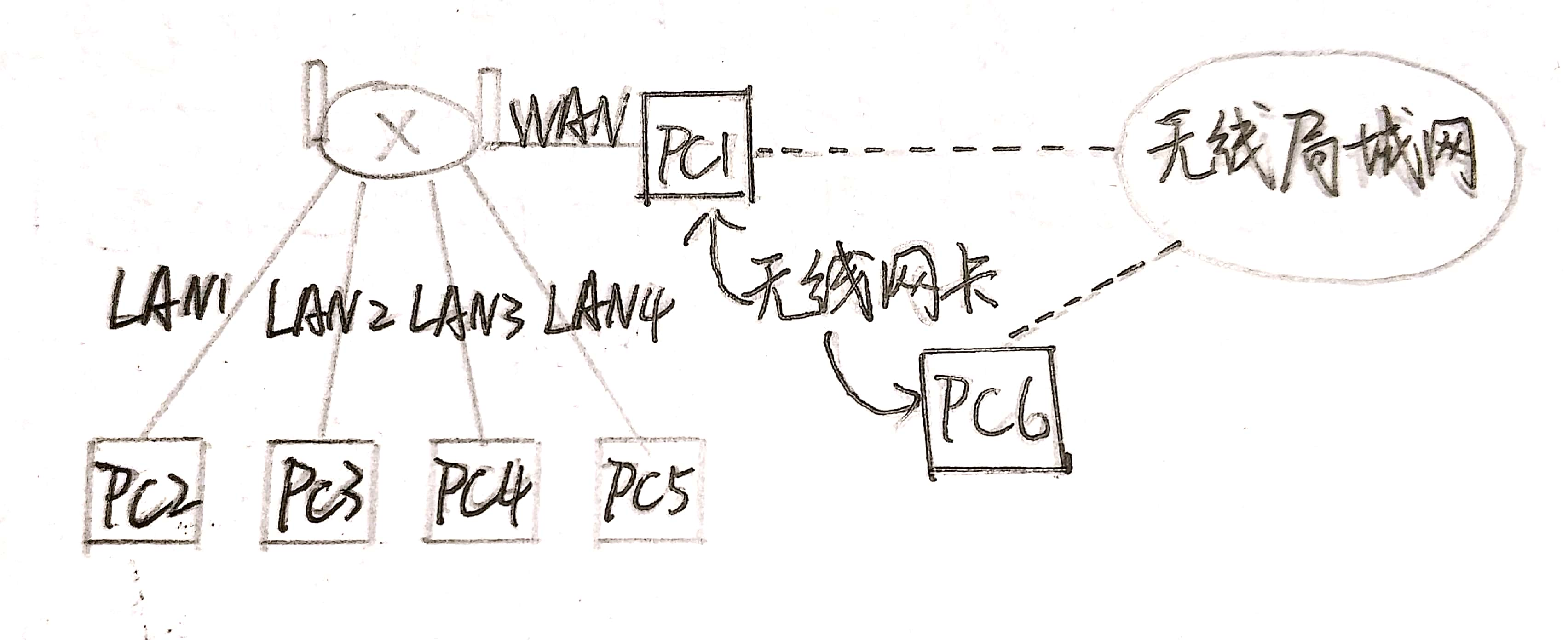
无线网络配置及通讯
- 每组发一个TPLINK 家用无线路由器,2 块无线网卡,要求每组电脑(6 台)全部同时联网


 5030
5030


 被折叠的 条评论
为什么被折叠?
被折叠的 条评论
为什么被折叠?
 到【灌水乐园】发言


