


基于原子F103精英版RS485实验工程的Freemodbus RTU的移植
资源准备及Freemodbus文件内容说明
移植FreeModbus版本为 FreeModbus V1.6提取码:1xkk
硬件平台为原子F103精英版,移植基础工程为 实验RS485通讯模板提取码:83gi
Freemodbus文件说明
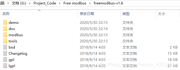
FreeModbus V1.6解压后打开文件夹后显示内容如下:
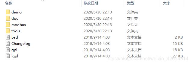
我们只关心 “demo”/“modbus”这两个文件夹
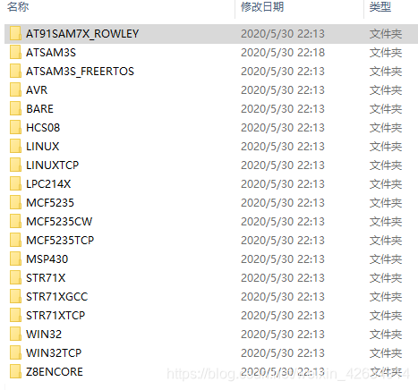
打开demo文件夹,显示内容为freemodbus支持的平台例程,stm32属于ARM平台,我们后续可参考"BARE"文件夹中的内容
打开BARE文件夹,显示内容如下:
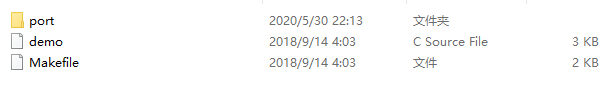
文件结构
| 源文件 | 描述 |
|---|---|
| port\port.h | 实现硬件移植部分接口 |
| port\portevent.c | 实现从机事件移植接口(需根据移植平台用户自行实现更改) |
| port\portserial.c | 从机串口移植(需根据移植平台用户自行实现更改) |
| port\porttimer.c | 从机定时器移植(需根据移植平台用户自行实现更改) |
| demo | 为工程实例定义从机数据缓冲区,实现从机Modbus 功能的回调接口(需用户根据需求自行实现更改) |
打开modbus文件夹,显示内容为freemodbus自身协议源码
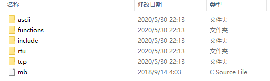
因为我们移植的是RTU通讯,所以暂且不用管ASCII TCP两个文件夹中的内容
文件结构
| 源文件 | 描述 |
|---|---|
| modbus\mb.c | 给应用层提供Modbus 从机设置及轮询相关接口 |
| modbus\functions\mbfunccoils.c | 从机线圈相关功能 |
| modbus\functions\mbfuncdisc.c | 从机离散输入相关功能 |
| modbus\functions\mbfuncholding.c | 从机保持寄存器相关功能 |
| modbus\functions\mbfuncinput.c | 从机输入寄存器相关功能 |
| modbus\functions\mbfuncother.c | 其余Modbus 功能 |
| modbus\functions\mbutils.c | 一些协议栈中需要用到的工具函数 |
| modbus\rtu\mbcrc.c | CRC 校验功能 |
| modbus\rtu\mbrtu.c | 从机RTU 模式设置及其状态机 |
| “include”文件夹内为modbus源代码的头文件存放文件夹 |
开始移植 Freemodbus到stm32平台工程中
移植之前我们需打开上文提到的freemodbus源文件及stm32 rs485实验工程
分别打开两个文件夹
工程文件内modbus文件夹内容的添加
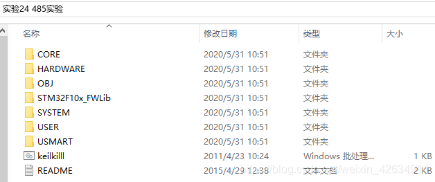
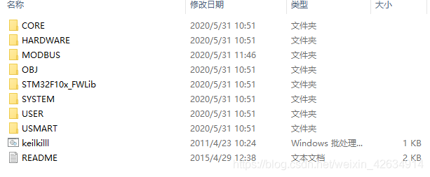
在485实验工程文件夹内新建"MODBUS"文件夹
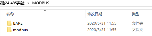
将freemodbus-v1.6“demo”文件夹中的BARE文件夹复制到MODBUS文件夹内
将freemodbus-v1.6“modbus”文件夹复制到MODBUS文件夹内
如下图所示
keil工程内modbus源码及头文件的添加
打开RS485基础工程,创建modbus工程组
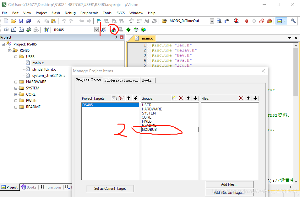
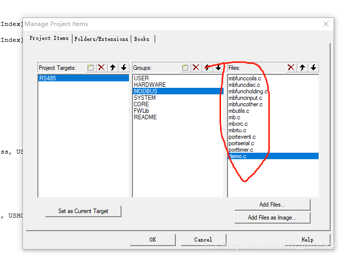
添加如下文件到工程组内,前面有提到它们所属的文件目录
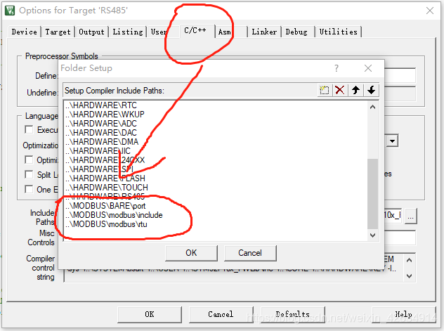
添加头文件路径
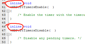
keil工程接口函数的补充及报错的解决
添加完成后,先编译一遍后出现报错,我们对如下文件进行更改,删除“porttimer.c”文件中下图两个函数前面的inline字符
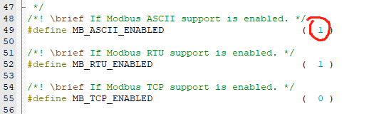
将“mbconfig.h”文件中的#define MB_ASCII_ENABLED ( 1 )改为(0)失能ASCII模式
将demo.c中的 int main函数删除,并对函数进行补充完善
具体更改后代码如下
#include "mb.h"
#include "mbport.h"

//保持寄存器
#define REG_HOLDING_START 0x0001    //起始为1,请看前面modbus rtu协议说明
#define REG_HOLDING_NREGS 4
uint16_t usRegHoldingBuf[REG_HOLDING_NREGS] = {0x0000,0x5678,0x5678,0x5678};

//输入寄存器
#define REG_INPUT_START 0x0001     //起始为1,请看前面modbus rtu协议说明
#define REG_INPUT_NREGS 4
uint16_t usRegInputBuf[REG_INPUT_NREGS] = {0x0000,0x1111,0x2222,0x3333};

/* ----------------------- Start implementation -----------------------------*/

/**
  *****************************************************************************
  * @Name   : 读输入寄存器
  * @Brief  : 对应功能码0x04 -> 读单个或多个输入寄存器eMBFuncReadInputRegister
  * @Input  : *pucRegBuffer数据缓冲区
  *           usAddress:     寄存器地址
  *           usNRegs:       寄存器数量
  * @Output : none
  * @Return : Modbus状态信息
  *****************************************************************************
**/
eMBErrorCode
eMBRegInputCB( UCHAR * pucRegBuffer, USHORT usAddress, USHORT usNRegs )
{
    eMBErrorCode    eStatus = MB_ENOERR;
    int             iRegIndex;
	//判断寄存器地址范围
    if( ( (int16_t)usAddress
					>= REG_INPUT_START )
						&& ( usAddress + usNRegs
							<= REG_INPUT_START
								+ REG_INPUT_NREGS ) )
    {
    	//计算偏移量
		iRegIndex = ( int )( usAddress - REG_INPUT_START );
        while( usNRegs > 0 )
        {
            *pucRegBuffer++ =
                ( unsigned char )( usRegInputBuf[iRegIndex] >> 8 );
            *pucRegBuffer++ =
                ( unsigned char )( usRegInputBuf[iRegIndex] & 0xFF );
            iRegIndex++;
            usNRegs--;
        }
    }
    else
    {
        eStatus = MB_ENOREG;
    }

    return eStatus;
}
/**
  *****************************************************************************
  * @Name   : 保持寄存器
  * @Brief  : 对应功能码0x03 -> 读单个或多个寄存器eMBFuncReadHoldingRegister
  * 				   0x06 -> 写单个保持寄存器eMBFuncWriteHoldingRegister
  * 				   0x10 -> 写多个保持寄存器eMBFuncWriteMultipleHoldingRegister
  * @Input  : *pucRegBuffer数据缓冲区
  *           usAddress:     寄存器地址
  *           usNRegs:       寄存器数量
  * @Output : none
  * @Return : Modbus状态信息
  *****************************************************************************
**/
eMBErrorCode
eMBRegHoldingCB( UCHAR * pucRegBuffer, USHORT usAddress, USHORT usNRegs,
                 eMBRegisterMode eMode )
{

	eMBErrorCode eStatus = MB_ENOERR;

	int16_t iRegIndex;

	//判断寄存器地址范围
	if(((int16_t)usAddress
								>= REG_HOLDING_START)
									&&(usAddress + usNRegs
										<= REG_HOLDING_START
											+ REG_HOLDING_NREGS))
	{
		//计算偏移量
		iRegIndex = (uint16_t)(usAddress - REG_HOLDING_START );
		switch(eMode)
		{
			//读操作
			case MB_REG_READ:
				while(usNRegs > 0)
				{
					*pucRegBuffer++ = (uint8_t)(usRegHoldingBuf[iRegIndex] >> 8);
					*pucRegBuffer++ = (uint8_t)(usRegHoldingBuf[iRegIndex] & 0XFF);
					iRegIndex++;
					usNRegs--;
				}
			break;

			//写操作
			case MB_REG_WRITE:
				while(usNRegs > 0)
				{
					usRegHoldingBuf[iRegIndex] = *pucRegBuffer++ <<8;
					usRegHoldingBuf[iRegIndex] |= *pucRegBuffer++;
					iRegIndex++;
					usNRegs--;
				}
				break;
		}
	}
	else
	{
		eStatus = MB_ENOREG;
	}
	return eStatus;
}

/**
  *****************************************************************************
  * @Name   : 线圈寄存器
  * @Brief  : 对应功能码0x01 -> 强制单线圈eMBFuncReadCoils
  * 				   0x05 -> 写单个线圈eMBFuncWriteCoil
  * 				   0x0F -> 写多个线圈eMBFuncWriteMultipleCoils
  * @Input  : *pucRegBuffer数据缓冲区
  *           usAddress:     寄存器地址
  *           usNRegs:       寄存器数量
  * @Output : none
  * @Return : Modbus状态信息
  *****************************************************************************
**/
eMBErrorCode
eMBRegCoilsCB( UCHAR * pucRegBuffer, USHORT usAddress, USHORT usNCoils,
               eMBRegisterMode eMode )
{
    return MB_ENOREG;
}
/**
  *****************************************************************************
  * @Name   : 操作离散量寄存器
  * @Brief  : 对应功能码0x02 -> 读输入状态eMBFuncReadDiscreteInputs
  * @Input  : *pucRegBuffer数据缓冲区
  *           usAddress:     寄存器地址
  *           usNRegs:       寄存器数量
  * @Output : none
  * @Return : Modbus状态信息
  *****************************************************************************
**/
eMBErrorCode
eMBRegDiscreteCB( UCHAR * pucRegBuffer, USHORT usAddress, USHORT usNDiscrete )
{
    return MB_ENOREG;
}
更改完后编译还会有错误,我们先不管,先添加modbus所需的硬件接口函数
- portserial.c文件的补充,先修改工程内的rs485.c 与rs485.
rs485.c修改如下
#include "sys.h"
#include "rs485.h"
#include "delay.h"


void RS485_Init(u32 bound)
{
  	GPIO_InitTypeDef GPIO_InitStructure;
  	USART_InitTypeDef USART_InitStructure;
 	NVIC_InitTypeDef NVIC_InitStructure;

	RCC_APB2PeriphClockCmd(RCC_APB2Periph_GPIOA|RCC_APB2Periph_GPIOD, ENABLE);
	RCC_APB1PeriphClockCmd(RCC_APB1Periph_USART2,ENABLE);

	GPIO_InitStructure.GPIO_Pin = GPIO_Pin_7;
 	GPIO_InitStructure.GPIO_Mode = GPIO_Mode_Out_PP;
 	GPIO_InitStructure.GPIO_Speed = GPIO_Speed_50MHz;
 	GPIO_Init(GPIOD, &GPIO_InitStructure);

	GPIO_InitStructure.GPIO_Pin = GPIO_Pin_2;	//PA2
  	GPIO_InitStructure.GPIO_Mode = GPIO_Mode_AF_PP;
 	GPIO_Init(GPIOA, &GPIO_InitStructure);
  	GPIO_InitStructure.GPIO_Pin = GPIO_Pin_3;//PA3
  	GPIO_InitStructure.GPIO_Mode = GPIO_Mode_IN_FLOATING;
  	GPIO_Init(GPIOA, &GPIO_InitStructure);

	RCC_APB1PeriphResetCmd(RCC_APB1Periph_USART2,ENABLE);
	RCC_APB1PeriphResetCmd(RCC_APB1Periph_USART2,DISABLE);
	USART_InitStructure.USART_BaudRate = bound;
	USART_InitStructure.USART_WordLength = USART_WordLength_8b;
	USART_InitStructure.USART_StopBits = USART_StopBits_1;
	USART_InitStructure.USART_Parity = USART_Parity_No;
	USART_InitStructure.USART_HardwareFlowControl = USART_HardwareFlowControl_None;
	USART_InitStructure.USART_Mode = USART_Mode_Rx | USART_Mode_Tx;
    USART_Init(USART2, &USART_InitStructure);

	NVIC_InitStructure.NVIC_IRQChannel = USART2_IRQn;
	NVIC_InitStructure.NVIC_IRQChannelPreemptionPriority = 1;
	NVIC_InitStructure.NVIC_IRQChannelSubPriority = 0;
	NVIC_InitStructure.NVIC_IRQChannelCmd = ENABLE;
	NVIC_Init(&NVIC_InitStructure);
    USART_Cmd(USART2, ENABLE);
    RS485_TX_EN=0;
}
rs485.h修改如下
#ifndef __RS485_H
#define __RS485_H
#include "sys.h"

#define RS485_TX_EN		PDout(7)	//.0,RX;1,TX.

void RS485_Init(u32 bound);

#endif
portserial.c补充如下
#include "rs485.h"
#include "port.h"

/* ----------------------- Modbus includes ----------------------------------*/
#include "mb.h"
#include "mbport.h"

/* ----------------------- static functions ---------------------------------*/
static void prvvUARTTxReadyISR( void );
static void prvvUARTRxISR( void );

/* ----------------------- Start implementation -----------------------------*/
void
vMBPortSerialEnable( BOOL xRxEnable, BOOL xTxEnable )
{
    /* If xRXEnable enable serial receive interrupts. If xTxENable enable
     * transmitter empty interrupts.
     */
	if(xRxEnable)
	{
		RS485_TX_EN = 0;	//发送后默认置低 接收
		USART_ITConfig(USART2,USART_IT_RXNE,ENABLE);
	}
	else
	{
		USART_ITConfig(USART2,USART_IT_RXNE,DISABLE);
	}

	if(xTxEnable)
	{
		RS485_TX_EN = 1;   //发送前置高
		USART_ITConfig(USART2,USART_IT_TXE,ENABLE);
	}
	else
	{
		USART_ITConfig(USART2,USART_IT_TXE,DISABLE);
	}

}

BOOL
xMBPortSerialInit( UCHAR ucPORT, ULONG ulBaudRate, UCHAR ucDataBits, eMBParity eParity )
{
	  (void)ucPORT;
	  (void)ucDataBits;
	  (void)eParity;

	   RS485_Init(ulBaudRate);
   	   return TRUE;
}
void vMBPortClose(void)
{
	USART_ITConfig(USART2, USART_IT_TXE | USART_IT_RXNE, DISABLE);
	USART_Cmd(USART2, DISABLE);
}

BOOL
xMBPortSerialPutByte( CHAR ucByte )
{
    /* Put a byte in the UARTs transmit buffer. This function is called
     * by the protocol stack if pxMBFrameCBTransmitterEmpty( ) has been
     * called. */

		USART_SendData(USART2,ucByte);
		while(USART_GetFlagStatus(USART2,USART_FLAG_TC)==RESET)
		{

		};
    	return TRUE;
}

BOOL
xMBPortSerialGetByte( CHAR * pucByte )
{
    /* Return the byte in the UARTs receive buffer. This function is called
     * by the protocol stack after pxMBFrameCBByteReceived( ) has been called.
     */
		*pucByte = USART_ReceiveData(USART2);
    return TRUE;
}

/* Create an interrupt handler for the transmit buffer empty interrupt
 * (or an equivalent) for your target processor. This function should then
 * call pxMBFrameCBTransmitterEmpty( ) which tells the protocol stack that
 * a new character can be sent. The protocol stack will then call
 * xMBPortSerialPutByte( ) to send the character.
 */
static void prvvUARTTxReadyISR( void )
{
    pxMBFrameCBTransmitterEmpty(  );
}

/* Create an interrupt handler for the receive interrupt for your target
 * processor. This function should then call pxMBFrameCBByteReceived( ). The
 * protocol stack will then call xMBPortSerialGetByte( ) to retrieve the
 * character.
 */
static void prvvUARTRxISR( void )
{
    pxMBFrameCBByteReceived(  );
}

void USART2_IRQHandler(void)
	{

		if(USART_GetITStatus(USART2, USART_IT_TXE) != RESET)
		{
				prvvUARTTxReadyISR();
				USART_ClearITPendingBit(USART2,USART_IT_TXE);
		}
		if(USART_GetITStatus(USART2, USART_IT_RXNE) != RESET)
		{
			  prvvUARTRxISR();
				USART_ClearITPendingBit(USART2,USART_IT_RXNE);
		}
}
- porttimer.c文件的补充, porttimer.c文件修改如下
/* ----------------------- Platform includes --------------------------------*/
#include "port.h"
#include "timer.h"
#include "sys.h"
/* ----------------------- Modbus includes ----------------------------------*/
#include "mb.h"
#include "mbport.h"

/* ----------------------- static functions ---------------------------------*/
static void prvvTIMERExpiredISR( void );

/* ----------------------- Start implementation -----------------------------*/
BOOL
xMBPortTimersInit( USHORT usTim1Timerout50us )
{
	TIM2_Int_Init(usTim1Timerout50us,(SystemCoreClock /20000)-1);//20KHZ
	return TRUE;
}


void
vMBPortTimersEnable(  )
{
    /* Enable the timer with the timeout passed to xMBPortTimersInit( ) */
	TIM_ClearITPendingBit(TIM2,TIM_IT_Update);
	TIM_ITConfig( TIM2,TIM_IT_Update,ENABLE);
	TIM_SetCounter(TIM2,0);
	TIM_Cmd(TIM2,ENABLE);
}

void
vMBPortTimersDisable(  )
{
  /* Disable any pending timers. */
	TIM_ClearITPendingBit(TIM2,TIM_IT_Update);
	TIM_ITConfig( TIM2,TIM_IT_Update,DISABLE);
	TIM_SetCounter(TIM2,0);
	TIM_Cmd(TIM2,DISABLE);
}

/* Create an ISR which is called whenever the timer has expired. This function
 * must then call pxMBPortCBTimerExpired( ) to notify the protocol stack that
 * the timer has expired.
 */
static void prvvTIMERExpiredISR( void )
{
    ( void )pxMBPortCBTimerExpired(  );
}

void TIM2_IRQHandler(void)
{
	if (TIM_GetITStatus(TIM2, TIM_IT_Update) != RESET)

		{
			TIM_ClearFlag(TIM2,TIM_FLAG_Update);
			TIM_ClearITPendingBit(TIM2, TIM_IT_Update  );
			prvvTIMERExpiredISR();
		}
}
- main.c文件修改如下
#include "delay.h"
#include "mb.h"
#include "rs485.h"


 int main(void)
 {
	delay_init();
	NVIC_PriorityGroupConfig(NVIC_PriorityGroup_4);//中断分组4 4位优先级抢占位 0位从优先级

	//初始化 RTU模式  地址0x01  端口号2(这里默认串口2可填为0)  波特率9600  无校验
 	eMBInit(MB_RTU,	0X01,0x02,9600,MB_PAR_NONE);

	eMBEnable();			//开启FreeModbus

	while(1)
	{
		eMBPoll();			//FreeModbus轮询
	}
}

#ifdef USE_FULL_ASSERT
void assert_failed(uint8_t *file,uint32_t line)
{
	while(1)
}

#else
void __aeabi_assert(const char *x1,const char *x2,int x3)
{
}
#endif
再进行全局编译,无错误提示,两个告警不用理会
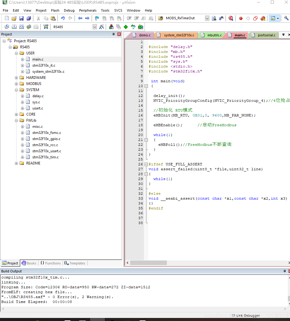
至此整个FreeModbus的移植过程结束,后面在开发板上进行各功能的验证。


 656
656


 被折叠的 条评论
为什么被折叠?
被折叠的 条评论
为什么被折叠?
 到【灌水乐园】发言


