


 本文介绍了如何使用STM32F103RCT6微控制器和ACS712霍尔电流传感器,配合电流互感器测量交流电流。通过配置STM32CubeMX和HAL库,实现ADC与TIM的DMA采集,从而实时监测电流变化。作者分享了电流互感器的正确使用方法,并展示了Python数据分析电流数据的流程。
首先介绍一下我使用的板子和外设,首先是正点原子的ministm32,mcu为stm32f103rct6,使用的电流传感器为acs712霍尔电流传感器。
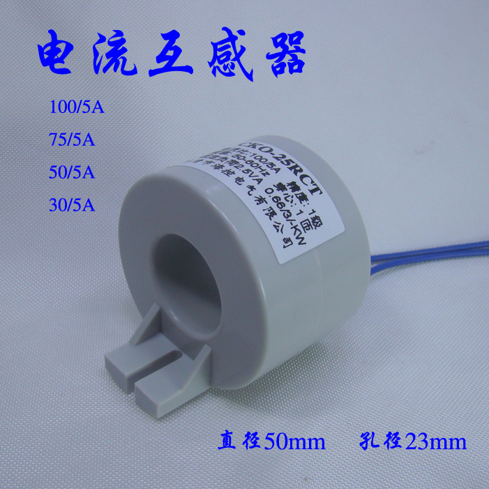
然后想要测量电流数据你还得需要一个电流互感器,我因为需要测量的是大电流所以购买的是转化比比较低的版本。
然后说说电流互感器的使用方法,一开始我直接将整根电线穿进去,发现没有电流的变化,后来经过老师指导发现你需要将插座导线的保护壳拆开,单独测量火线的值
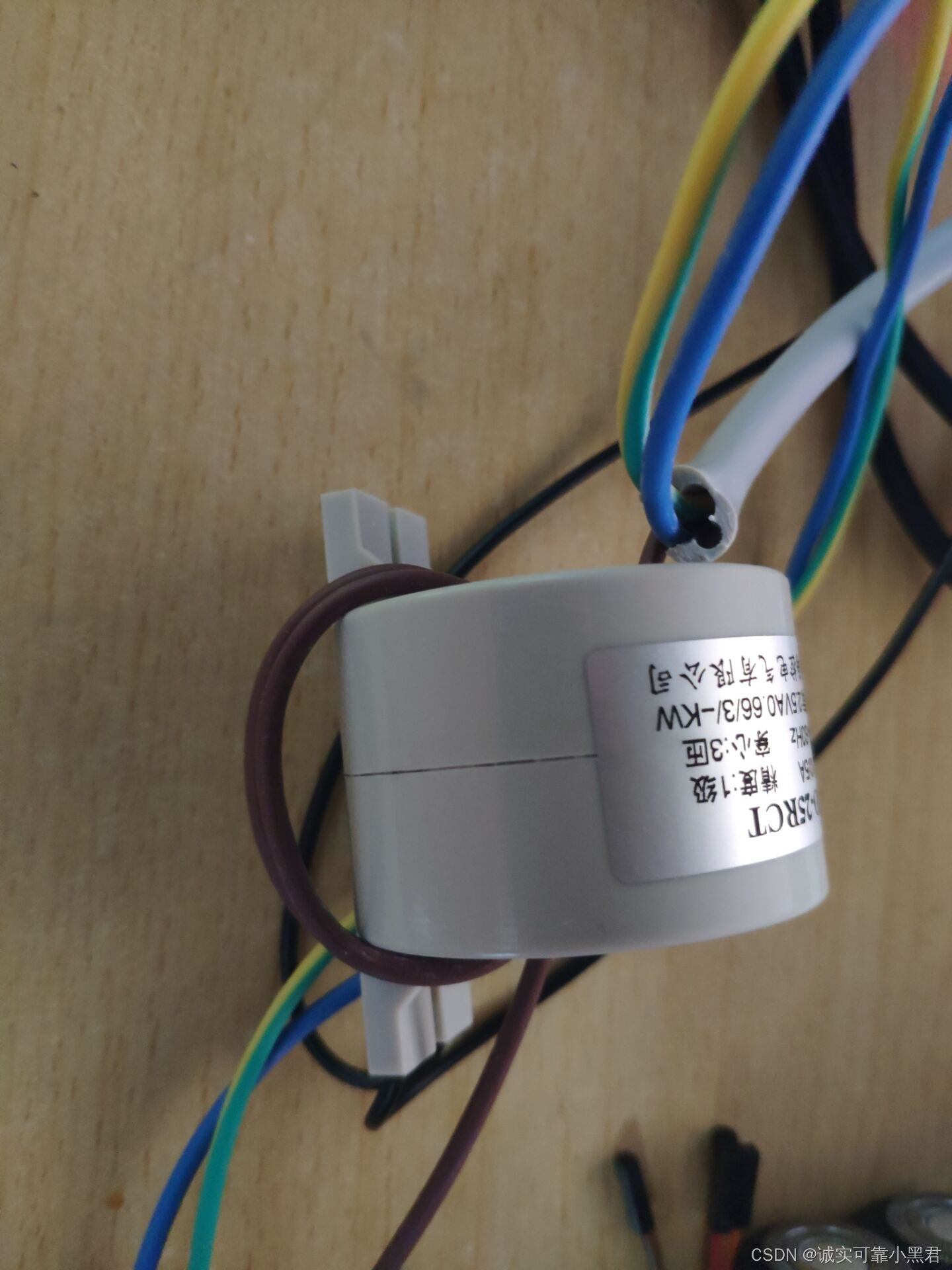
如图所示,我购买的是10/5A,穿心3匝(如果1匝则直接将火线穿过即可),所以需要多绕两圈(棕色的是火线),然后将电流互感器上的导线接到霍尔电流传感器上(接哪一头影响不大,可所以接)。
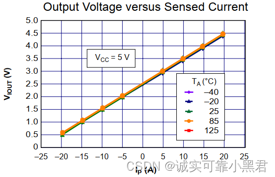
然后讲讲霍尔电流测量电流的方法,理论上就是通过测量电流值,输出电压值,然后我们可以根据adc读取到的电压值结合原理图来反推电流值。如图所示(不同量程的图不同,根据自己购买的型号进行换算),举个例子,如果adc读取到3v电压,那么测量到的电流值大约为5A:
说完原理我们再来通过stm32cubemx来生成相关代码,这里我直接转载西瓜大大的文章,根据他的教程来即可生成代码
STM32HAL ADC+TIM+DMA采集交流信号 基于cubemx_四臂西瓜的博客-CSDN博客_基于stm32的交流信号采集程序
在tim3的设置教程中根据自己需要的采样率进行修改,比如我需要的是10Khz,则将其修改为7200-1
这里只贴上需要修改的代码:分别在main.c的51和107行
uint16_t adc_buff[1000];//存放ADC采集的数据 HAL_ADC_Start_DMA(&hadc1, (uint32_t *)adc_buff, 1000); //让ADC1去采集1000个数,存放到adc_buff数组里
while (!AdcConvEnd) ; //等待转换完毕
for (uint16_t i = 0; i < 1000; i++)
{
//printf("\r\n电流数据为:\r\n");
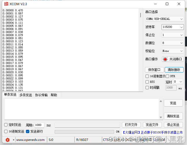
printf("\r%.5f %.3f\r\n",i*0.00001,adc_buff[i] * 3.3 / 4095*5 - 2.480*5); //数据打印,查看结果
}则打印出来的0电流(即排插没有接其他电器)时数据如下,左边是时间,单位为s,右边为电流数据,单位为A,记得将波特率设置为115200,否则会乱码。
然后通过Python打印
import matplotlib.pyplot as plt
import numpy as np

data = np.loadtxt('computer.txt')

plt.plot(data[:,0],data[:,1])
plt.xlabel("Time(s)")
plt.ylabel("Current(A)")
plt.show()
图片如下
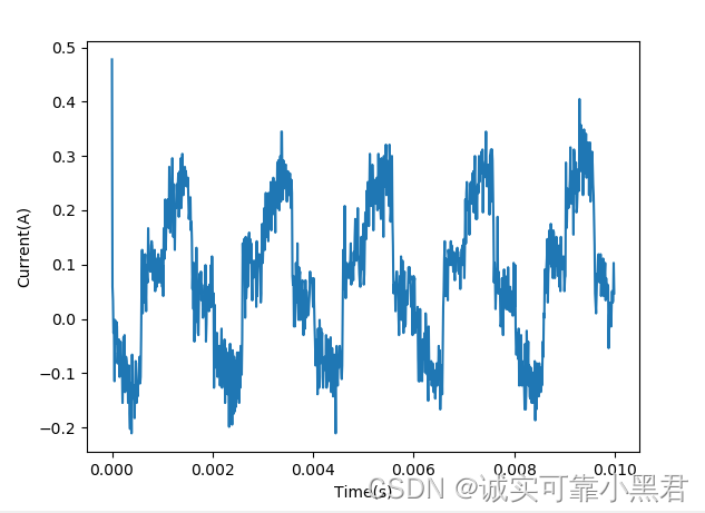
该图为笔记本电脑充电时的数据。
测试完毕。


 572
572

 被折叠的 条评论
为什么被折叠?
被折叠的 条评论
为什么被折叠?
 到【灌水乐园】发言


