


 本文详细介绍了如何在LabVIEW中利用OPC服务器与三菱FX3U PLC进行通信。首先,需要下载并安装OPC服务器和数据记录与监控模块。接着,配置OPC服务器,添加新通道并设置通信参数。然后,在LabVIEW中创建I/O服务器,选择OPCClient,并绑定变量。最后,通过新建VI直接在程序框图中操作软元件实现读写PLC数据。
LabVIEW使用OPC与PLC通信是十分便捷的,下面讲一下LabVIEW与PLC之间如何通过OPC通信。
1.软件的准备,对于初次安装的LabVIEW,需要在NI Pacage Manger中另外下载OPC服务器(图1)和数据记录与监控模块,数据记录与监控模块需要与所在电脑的labVIEW版本一致,我这里使用的是32 位的LabVIEW2020(如图 2)。
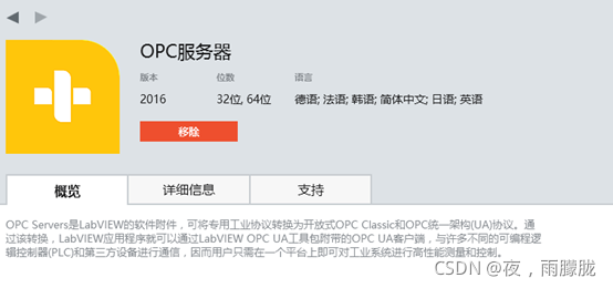
图1 OPC服务器模块
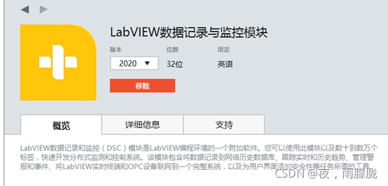
图2 数据记录与监控模块
2.在所有软件中找到OPC Serves Configuration(图3),打开后的软件如图4所示
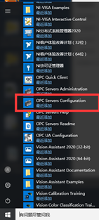
图3 OPC Serves Configuration位置
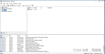
图4 软件界面
3.添加一个新的通道,修改通道名称后,点击下一步,如图5所示
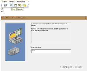
图5 添加一个新通道
4.选择对应的设备(图6),我选用的是三菱FX3U的PLC,所以选择Mitsubishi FX 选项,点击下一步,修改通信参数,然后一直点击下一步,直至完成。
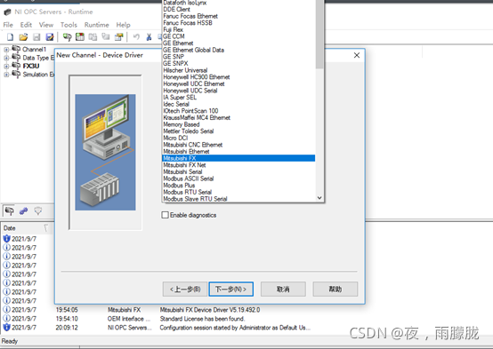
图6 选择对应的设备
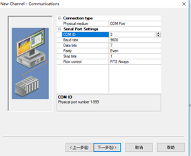
图7 修改通信参数
5.至此一个新的通道就建好了(图7),
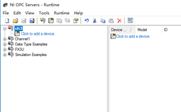
图7 新建通道
6.点击click to add a device,然后弹出对话框如图8所示;点击下一步,选择对应的PLC型号,如图9所示;一直点击下一步,直至完成。
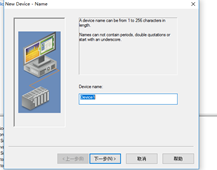
图8 弹出对话框
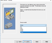
图9 选择对应PLC型号
7.双击Click to add static tag,添加需要用到的软元件(图10)。
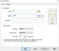
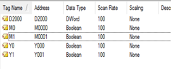
图10 添加需要用到的软元件
8.点击第二行最后一个图标Quick Client,监控PLC数据。
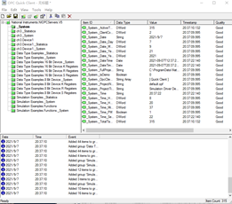
图11 监控PLC数据
9.打开LabVIEW,新建一个空白项目,在我的电脑选项新建一个I/O服务器,在弹出的窗口选择OPC Client选项,点击继续。
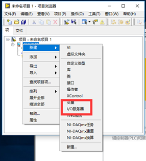
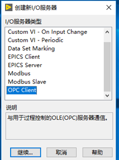
图12 添加OPC Client
10.在弹出窗口中,选择National Instruments.NIOPCServers.v5选项,点击OK,添加完成
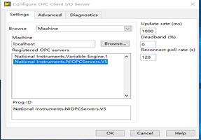
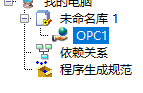
图13 选择National Instruments.NIOPCServers.v5
11.右击OPC1,选择创建绑定变量,添加对应的软元件,点击确定。要是没有在OPC Serve中配置的设备,重复第9步和第10步,在第10步中选择与上次不同的选项。
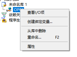
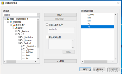
图14 绑定变量
12.至此准备工作全部完成,在项目栏中可看到显示的软元件
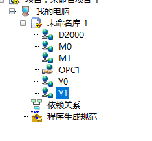
图15 显示的软元件
13.新建一个VI,对需要用到的软元件可以直接从项目栏中拖进程序框图,通过改变访问模式对软元件进行读写操作。
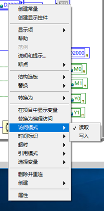
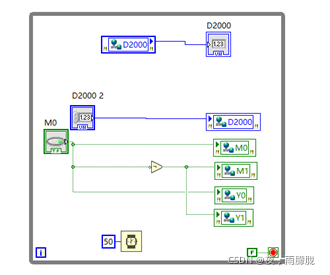
图16 将软元件加入程序中


 2968
2968

 被折叠的 条评论
为什么被折叠?
被折叠的 条评论
为什么被折叠?
 到【灌水乐园】发言


