


在计算机视觉领域,模板匹配是一项基础且关键的技术,用于在一幅大图像中寻找与给定模板图像最相似的区域。然而,目前opencv中自带的模板匹配函数cv::matchTemplate()只能达到像素级别的精度。而基于像素级别的模板匹配方法往往受限于其精度,难以满足一些对定位精度要求极高的应用场景。因此,在一些精密仪器的检测中,往往需要更高的精度,这时,亚像素精度模板匹配便显得尤为重要。
一、什么是亚像素精度?
简单来说,亚像素精度指的是能够定位到小于一个像素单位的位置的能力。这意味着即使在数字图像(由离散像素组成)中,我们也能精确地确定目标位置,精度可以达到小数点后几位的像素级别。这对于需要高精度的应用场景,如工业检测、医学影像分析等,具有重要意义。
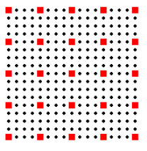
亚像素精度指的是在两个相邻像素之间进一步细分的技术,常见的细分比例包括二分之一、三分之一或四分之一。通过这种技术,每个像素被划分为更小的单元,并在这些单元上应用插值算法以提高定位精度。例如,当选择四分之一的亚像素精度时,意味着每个像素在水平和垂直方向上都被视为四个独立的小单元进行处理。因此,对于一张5x5像素的图像,采用四分之一亚像素精度后,相当于将其转换为一个20x20的离散点阵(而非16x16),从而能够在更精细的尺度上执行插值操作,显著提升了定位的精确度。
二、为什么选择模板匹配?
模板匹配是一种简单而有效的局部特征描述方法,适用于对象识别、目标跟踪等多种任务。通过比较模板图像和待搜索图像之间的相似度,可以找到最佳匹配位置。然而,在某些情况下,尤其是当存在尺度变化、旋转或部分遮挡时,传统方法可能无法提供足够的准确性。

三、如何实现亚像素精度模板匹配?
要在模板匹配中达到亚像素精度,可以通过以下几种方式:
- 插值法:在找到最佳匹配位置附近使用插值技术(如双线性插值、三次样条插值等),估计更精确的位置。
- 曲面拟合算法:将离散点进行拟合成函数,计算出极值位置。
四、OpenCV中的实现示例
下面是一个亚像素模板匹配的例子,演示如何在OpenCV中实现带有亚像素精度的模板匹配。
#include "pch.h"
#include <iostream>
#include <opencv2/opencv.hpp>
using namespace std;
using namespace cv;
#ifndef FLT_EPSILON
#define FLT_EPSILON 1.192092896e-07F /* smallest such that 1.0+FLT_EPSILON != 1.0 */
#endif
#ifndef _ASSERT
#define _ASSERT
#endif
void SubPixFitParabola(cv::Point2d* Result, cv::Point2d& P1, cv::Point2d& P2, cv::Point2d& P3);
double minMaxLocSubPix(CV_OUT cv::Point2d* SubPixLoc, cv::InputArray src,
CV_IN_OUT cv::Point* LocIn, CV_IN_OUT const int Method);
int main()
{
///单模板匹配
Mat temp = imread("temp.bmp"); //模板图像
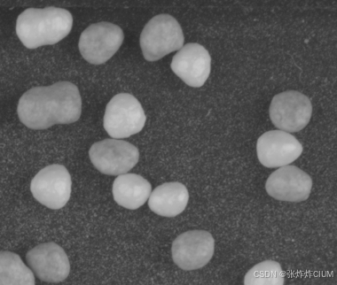
Mat src = imread("src.bmp"); //待搜索图像
//imshow("temp", temp);
//imshow("src", src);
Mat dst = src.clone(); //原图备份
int width = src.cols - temp.cols +1; //result 宽度
int height = src.rows - temp.rows +1; //result 高度
Mat result(height, width, CV_32FC1); //创建结果映射图像
matchTemplate(src, temp, result, TM_CCOEFF_NORMED); //化相关系数匹配最佳值 1
//imshow("result", result);
normalize(result, result, 0, 1, NORM_MINMAX, -1); //归一化到0--1范围
double minValue, maxValue;
Point minLoc, maxLoc;
minMaxLoc(result, &minValue, &maxValue, &minLoc, &maxLoc);
cout << "minValue=" << minValue << endl;
cout << "maxValue=" << maxValue << endl;
cout << "maxLoc:" << maxLoc <<endl;
Point2d subPixLoc;
minMaxLocSubPix(&subPixLoc, result, &maxLoc, 0);
cout << "subPixLoc:" << subPixLoc <<endl;
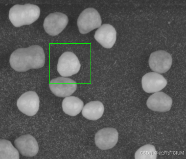
rectangle(dst, maxLoc, Point(maxLoc.x+temp.cols, maxLoc.y+temp.rows), Scalar(0, 255, 0), 1, 8);
//imshow("dst", dst);
imwrite("result.bmp", dst);
waitKey(0);
return 0;
}
double minMaxLocSubPix(CV_OUT cv::Point2d* SubPixLoc, cv::InputArray src,
CV_IN_OUT cv::Point* LocIn,CV_IN_OUT const int Method)
{
/*
input:
src = Heat map. It must be single-channel 32-bit floating-point
LocIn = X,y location you want to start with. This is normally from MinMaxLoc, however you can explore other peaks.
Method = -1 to disable math for testing, 0 for the best we have, 1 for this parabola curve fit version
output:
SubPixLoc = location adjusted with improved precision.
notes:
If you rescale the heat map after match template... you must also adjust LocIn to match.
*/
// set default result in case we bail
SubPixLoc->x = (float)LocIn->x;
SubPixLoc->y = (float)LocIn->y;
if (Method == -1) { // disable any changes for testing
return 0;
};
// At this time we don't have anything other than Parabola math so we can ignore "Method".
{ // Parabola math
/*
The values returned from MatchTemplate are not linear past the point where it just starts to drop.
The reason is that we can not assume that the template is the same on all sides. Imagine a sloped edge on one side and a sharp edge on the other.
We can also get several values at the top that are all the same since the source and the template are integers.
We also have to protect against the situation where the source is a solid white or solid black. The result is a constant value heat map.
*/
Mat HeatMap = src.getMat();
// pick some limiting values
// It's not expected that the template peak values will span more than 1/16 of the source size. This also limits the processing time used when looking at a blank image.
Size MaxScan; MaxScan.width = HeatMap.cols >> 4; MaxScan.height = HeatMap.rows >> 4;
Point ScanRectMin; // I used two Points instead of a Rect to prevent having Rect compute right/left values in each loop below
Point ScanRectMax;
ScanRectMin.x = LocIn->x - MaxScan.width; if (ScanRectMin.x < 0) ScanRectMin.x = 0;
ScanRectMin.y = LocIn->y - MaxScan.height; if (ScanRectMin.y < 0) ScanRectMin.y = 0;
ScanRectMax.x = LocIn->x + MaxScan.width; if (ScanRectMax.x >= HeatMap.cols) ScanRectMax.x = HeatMap.cols - 1;
ScanRectMax.y = LocIn->y + MaxScan.height; if (ScanRectMax.y >= HeatMap.rows) ScanRectMax.y = HeatMap.rows - 1;
// were we are starting at
const float FloatValueChange = FLT_EPSILON * 10.0f; // smallest change that we can do math on with some meaningful result.
// scan to find area to use. this can get complicated since we may be given a point near any of the edges of the blob we want to use.
float SrcStartingPoint = HeatMap.at<float>(LocIn->y, LocIn->x);
Point Center = *LocIn;
// results
Point ScanRight;
Point ScanLeft;
Point ScanUp;
Point ScanDown;
//for (int rescan = 0; rescan < 2; ++rescan){
ScanRight = Center;
while (true) {
++ScanRight.x; // no point checking the passed location. so inc first
if (ScanRight.x > ScanRectMax.x) {
// _ASSERT(0);
return 1; // ran out of room to scan
};
float Val = HeatMap.at<float>(ScanRight.y, ScanRight.x);
if (abs(Val - SrcStartingPoint) > FloatValueChange) {
break;
};
};
ScanLeft = Center;
while (true) {
--ScanLeft.x; // no point checking the passed location. so inc first
if (ScanLeft.x < ScanRectMin.x) {
// _ASSERT(0);
return 1; // ran out of room to scan
};
if (abs(HeatMap.at<float>(ScanLeft.y, ScanLeft.x) - SrcStartingPoint) > FloatValueChange) {
break;
};
};
ScanUp = Center;
while (true) {
++ScanUp.y; // assume G cords. The actual direction of Up in the image is not important since the math is symmetrical
if (ScanUp.y > ScanRectMax.y) {
// _ASSERT(0);
return 1; // ran out of room to scan
};
if (abs(HeatMap.at<float>(ScanUp.y, ScanUp.x) - SrcStartingPoint) > FloatValueChange) {
break;
};
};
ScanDown = Center;
while (true) {
--ScanDown.y; // assume G cords. The actual direction of Up in the image is not important since the math is symmetrical
if (ScanDown.y < ScanRectMin.y) {
// _ASSERT(0);
return 1; // ran out of room to scan
};
if (abs(HeatMap.at<float>(ScanDown.y, ScanDown.x) - SrcStartingPoint) > FloatValueChange) {
break;
};
};
// At this point we have a good starting point on the blob area, but our initial scan may be stuck on one side so center and rescan once more
//Center.x = ((ScanRight.x - ScanLeft.x) >> 1) + ScanLeft.x;
//Center.y = ((ScanUp.y - ScanDown.y) >> 1) + ScanDown.y;
// did center change?
//if ((Center.x == LocIn->x) && (Center.y == LocIn->y)) break; // done early
//}; // for rescan
// measure polarity if needed
// At this point we have a center of a blob with some extents to use
// for each axis we now do a triangulation math.
// imagine the match numbers as height and the pixel numbers as horizontal.
//B is highest, A and C are on the sides
double ErrorVal = 0;
{// X axis
Point2d A;
A.x = ScanLeft.x; // The pixel cords
A.y = HeatMap.at<float>(ScanLeft.y, ScanLeft.x); // the Heat map value
Point2d B; // center
B.x = Center.x; // The pixel cords
B.y = HeatMap.at<float>(Center.y, Center.x); // the Heat map value
Point2d C;
C.x = ScanRight.x; // The pixel cords
C.y = HeatMap.at<float>(ScanRight.y, ScanRight.x); // the Heat map value
Point2d Result;
SubPixFitParabola(&Result, A, B, C);
// we throw away the y and use the x
// clip and set error
if (Result.x < ScanLeft.x) {
_ASSERT(0);
Result.x = ScanLeft.x;
ErrorVal = 1;
};
if (Result.x > ScanRight.x) {
_ASSERT(0);
Result.x = ScanRight.x;
ErrorVal = 1;
};
SubPixLoc->x = Result.x;
}; // X axis
{// Y axis
// this time we swap x and y since the parabola is always found in the x
Point2d A;
A.x = ScanDown.y; // The pixel cords
A.y = HeatMap.at<float>(ScanDown.y, ScanDown.x); // the Heat map value
Point2d B; // center
B.x = Center.y; // The pixel cords
B.y = HeatMap.at<float>(Center.y, Center.x); // the Heat map value
Point2d C;
C.x = ScanUp.y; // The pixel cords
C.y = HeatMap.at<float>(ScanUp.y, ScanUp.x); // the Heat map value
Point2d Result;
SubPixFitParabola(&Result, A, B, C);
// we throw away the y and use the x
Result.y = Result.x;
// clip and set error
if (Result.y < ScanDown.y) {
_ASSERT(0);
Result.y = ScanDown.y;
ErrorVal = 1;
};
if (Result.y > ScanUp.y) {
_ASSERT(0);
Result.y = ScanUp.y;
ErrorVal = 1;
};
SubPixLoc->y = Result.y;
}; // X axis
return ErrorVal;
}; // Bill's Tilt math
return 0;
};
// Parabolic fit
void SubPixFitParabola(cv::Point2d* Result, cv::Point2d& P1, cv::Point2d& P2, cv::Point2d& P3)
{
/*
Parabola fit and resulting peak
The parabola is aligned along the X axis with the peak being in the Y.
input:
P1 = a point on one side
P2 = the center point
P3 = a point on the other side
output:
Result = the peak point in the center of the parabola
*/
Result->x = P2.x; // default in case of an error
Result->y = P2.y;
/* from http://stackoverflow.com/questions/717762/how-to-calculate-the-vertex-of-a-parabola-given-three-points
This is really just a simple linear algebra problem, so you can do the calculation symbolically. When you substitute in the x and y values of your three points, you'll get three linear equations in three unknowns.
A x1^2 + B x1 + C = y1
A x2^2 + B x2 + C = y2
A x3^2 + B x3 + C = y3
The straightforward way to solve this is to invert the matrix
x1^2 x1 1
x2^2 x2 1
x3^2 x2 1
and multiply it by the vector
y1
y2
y3
The result of this is... okay, not exactly all that simple ;-) I did it in Mathematica, and here are the formulas in pseudocode:
*/
double denom = (P1.x - P2.x) * (P1.x - P3.x) * (P2.x - P3.x); // can't be zero since X is from pixel locations.
double A = (P3.x * (P2.y - P1.y) + P2.x * (P1.y - P3.y) + P1.x * (P3.y - P2.y)) / denom;
double B = ((P3.x * P3.x) * (P1.y - P2.y) + (P2.x * P2.x) * (P3.y - P1.y) + (P1.x * P1.x) * (P2.y - P3.y)) / denom;
double C = (P2.x * P3.x * (P2.x - P3.x) * P1.y + P3.x * P1.x * (P3.x - P1.x) * P2.y + P1.x * P2.x * (P1.x - P2.x) * P3.y) / denom;
// y = A * x^2 + B * x + C
//now find the center
double xv = -B / (2 * A);
double yv = C - (B*B) / (4 * A);
Result->x = xv;
Result->y = yv;
};
最终可以获得亚像素位置结果
五、总结
本文介绍了亚像素精度模板匹配的概念及其重要性,并通过一个具体的OpenCV实例展示了如何实现这种高级匹配技术。
但是这个模板匹配还只是匹配单目标,且目标不能存在多角度等。后续会在此基础上,逐步加入,金字塔匹配加速,多角度,多目标以及多尺度的亚像素匹配。
希望这篇博客能为您提供有价值的参考,帮助您更好地理解和应用这一强大的图像处理工具。未来,随着深度学习等新技术的发展,我们期待看到更多创新性的模板匹配解决方案出现。


 2553
2553

 被折叠的 条评论
为什么被折叠?
被折叠的 条评论
为什么被折叠?
 到【灌水乐园】发言


