关于28379D开发板的CAN通讯以及开发板的主频问题

本文记录用ti的TMS320F28379D LaunchPad调CAN通讯的过程,最后会给出代码。

用的是CCS11.1版本加上ti的C2000ware的库。


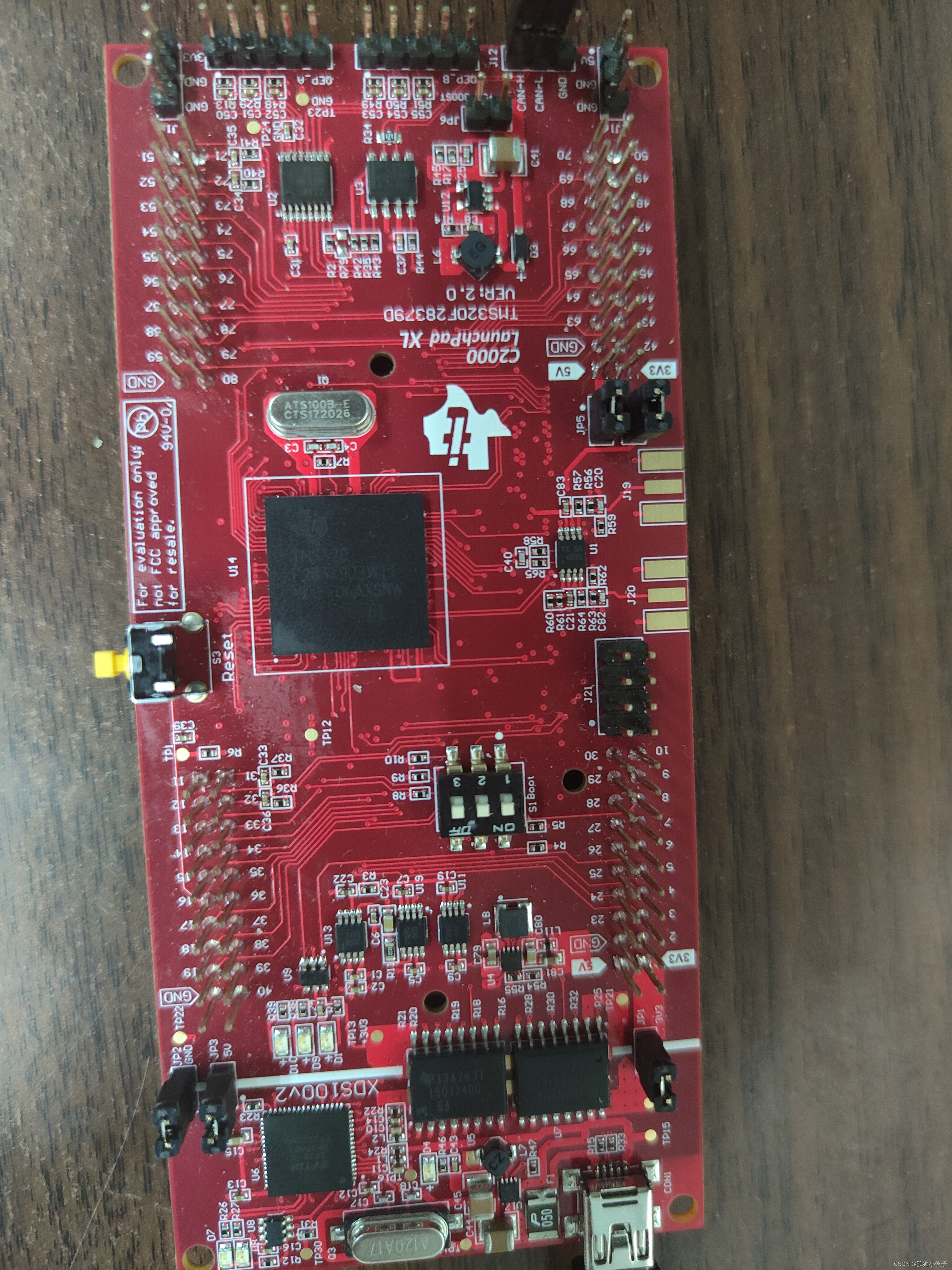
一开始用的是C2000ware库中的can_ex4_simple_transmit中的程序,把复用引脚改为开发板上的GPIO12和GPIO17引脚,上位机一直采集不到。排除了很久,发现CAN的比特率不对,跟程序设置的不一样。看这个帖子有感,想查一查系统的主频是多少。TI C2000WARE官方例程时钟配置的坑(针对TMS320F28379D LaunchPad XL) / DSP / WhyCan Forum(哇酷开发者社区)

系统的延迟函数DEVICE_DELAY_US()是以微妙为单位的,推测内层函数是汇编写的(时间测量比较准确),所以用它跟GPIO配合,测量系统的频率。

 Device_initGPIO();
 GPIO_setPadConfig(61, GPIO_PIN_TYPE_PULLUP);   // Enable pullup on GPIO6 先启动输入上拉
 GPIO_setPinConfig(GPIO_61_GPIO61);             //配置复用
 GPIO_setDirectionMode(61, GPIO_DIR_MODE_OUT);  // GPIO6 = output  配置IO口的输入以及输出方向
 while(1)
 {
        GPIO_writePin(61, 1);                          // Load output latch
        DEVICE_DELAY_US(50000);
        GPIO_writePin(61, 0);                          // Load output latch
        DEVICE_DELAY_US(50000);
 }

用示波器测量GPIO61口的波形,示波器测量图见下图。

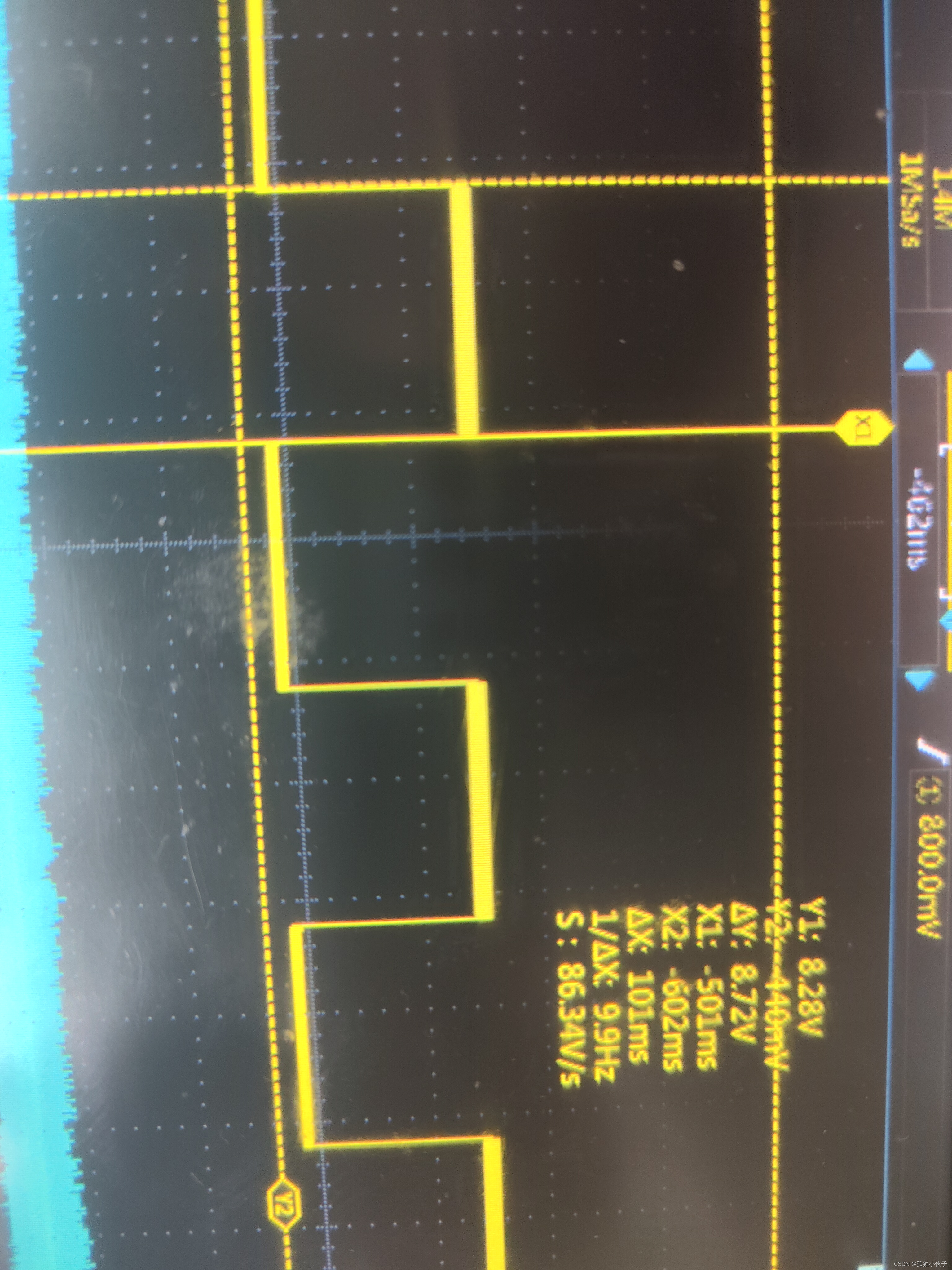
 从示波器中可以看到△x=100ms,即GPIO61口输出的高电平或者低电平的时间为100ms,而程序中的延迟函数设置的为50ms,由此可以看出系统主频慢了1/2.

从系统的初始化函数Device_init()(按住ctrl键点击这个函数之中)中找到SysCtl_setClock(DEVICE_SETCLOCK_CFG)语句,在按ctrl进入DEVICE_SETCLOCK_CFG,将参数改为下图所示。

 上图依次为系统的外部主频大小、PLL的倍数。改变上述系统时钟参数之后,看GPIO口的输出波形,见下图。

 看到GPIO口的输出波形高电平以及低电平持续时间变成了50ms,跟延时设定的时间一样。可以推断出系统原来的主频只为100Mhz,没有达到它可以运行的最高200Mhz。

回到can通信,当我把系统时钟按照上述步骤修改成主频为200Mhz的时候,C2000ware中的can_ex4_simple_transmit就可以在上位机采集到发送的数据。

下面是用开发板GPIO12和GPIO17做CANB发送引脚的通讯,250ms发送一次,接收中断,标志符为0x1,接收的数据可以在rxMsgData数组中看到。记得一定要按照上述步骤把系统时钟频率改掉!!!

#include "driverlib.h"
#include "device.h"

//
// Defines
//
#define MSG_DATARX_LENGTH    0   // "Don't care" for a Receive mailbox
#define MSG_DATATX_LENGTH    8
#define RX_MSG_OBJ_ID      10   // Use mailbox 1
#define TX_MSG_OBJ_ID      1
//
// Globals
//


uint16_t txMsgData[8];
uint16_t rxMsgData[8];

__interrupt void canbISR(void);     // Receive interrupt for CAN-B.
                                    // No Transmit interrupt for CAN-A
//
// Main
//
void main(void)
{
    //
    // Initialize device clock and peripherals
    //
    Device_init();

    //
    // Initialize GPIO
    //
    Device_initGPIO();

	//
    // Configure GPIO pins for CANTX/CANRX
	//
    GPIO_setPinConfig(GPIO_12_CANTXB);
    GPIO_setPinConfig(GPIO_17_CANRXB);

    //
    // Configure GPIO pin which is toggled upon message reception
	//
   // GPIO_setPadConfig(34U, GPIO_PIN_TYPE_STD);
   // GPIO_setDirectionMode(34U, GPIO_DIR_MODE_OUT);

    //
    // Initialize the CAN controller
    //
    CAN_initModule(CANB_BASE);

    //
    // Set up the CAN bus bit rate to 500kHz for each module
    // Refer to the Driver Library User Guide for information on how to set
    // tighter timing control. Additionally, consult the device data sheet
    // for more information about the CAN module clocking.
    //
    CAN_setBitRate(CANB_BASE, DEVICE_SYSCLK_FREQ, 500000, 20);


    CAN_enableInterrupt(CANB_BASE, CAN_INT_IE0 | CAN_INT_ERROR |
                           CAN_INT_STATUS);


    //
    // Initialize PIE and clear PIE registers. Disables CPU interrupts.
    //
    Interrupt_initModule();

     //
     // Initialize the PIE vector table with pointers to the shell Interrupt
     // Service Routines (ISR).
     //
     Interrupt_initVectorTable();


    //
    // Enable Global Interrupt (INTM) and realtime interrupt (DBGM)
    //


    //
    // Interrupts that are used in this example are re-mapped to
    // ISR functions found within this file.
    // This registers the interrupt handler in PIE vector table.
    //
    Interrupt_register(INT_CANB0, &canbISR);

    //
    // Enable the CAN-B interrupt signal
    //
    Interrupt_enable(INT_CANB0);

    //
    // Set GLBINT0_EN bit in CAN_GLB_INT_EN register
    //
    CAN_enableGlobalInterrupt(CANB_BASE, CAN_GLOBAL_INT_CANINT0);
    //
    // Start CAN module A operations
    //
    //
     // Initialize the receive message object used for receiving CAN messages.
     // Message Object Parameters:
     //      CAN Module: A
     //      Message Object ID Number: 1
     //      Message Identifier: 0x1
     //      Message Frame: Standard
     //      Message Type: Receive
     //      Message ID Mask: 0x0
     //      Message Object Flags: None
     //      Message Data Length: "Don't care" for a Receive mailbox
     //
     CAN_setupMessageObject(CANB_BASE, RX_MSG_OBJ_ID, 0x1,
                            CAN_MSG_FRAME_STD, CAN_MSG_OBJ_TYPE_RX, 0,
                            CAN_MSG_OBJ_RX_INT_ENABLE, MSG_DATARX_LENGTH);

     CAN_setupMessageObject(CANB_BASE, TX_MSG_OBJ_ID, 0x1,
                               CAN_MSG_FRAME_STD, CAN_MSG_OBJ_TYPE_TX, 1,
                               CAN_MSG_OBJ_TYPE_TX, MSG_DATATX_LENGTH);
     CAN_startModule(CANB_BASE);
        txMsgData[0] = 0x01;
        txMsgData[1] = 0x23;
        txMsgData[2] = 0x45;
        txMsgData[3] = 0x67;
        txMsgData[4] = 0x89;
        txMsgData[5] = 0xAB;
        txMsgData[6] = 0xCD;
        txMsgData[7] = 0xEF;
    //


        EINT;
           ERTM;
    // Start reception - Just wait for data from another node
	//
    while(1)
	{
                CAN_sendMessage(CANB_BASE, TX_MSG_OBJ_ID, MSG_DATATX_LENGTH, txMsgData);
                DEVICE_DELAY_US(2000000);
	}
}
__interrupt void
canbISR(void)
{
    uint32_t status;

    //
    // Read the CAN-B interrupt status (in the CAN_INT register) to find the
    // cause of the interrupt
    //
    status = CAN_getInterruptCause(CANB_BASE);

    //
    // If the cause is a controller status interrupt, then get the status.
    // During first iteration of every ISR execution, status = 0x8000,
    // which simply means CAN_ES != 0x07.
    //
    if(status == CAN_INT_INT0ID_STATUS)
    {
        //
        // Read the controller status.  This will return a field of status
        // error bits that can indicate various errors.  Error processing
        // is not done in this example for simplicity.  Refer to the
        // API documentation for details about the error status bits.
        // The act of reading this status will clear the interrupt.
        //
        status = CAN_getStatus(CANB_BASE);  // Return CAN_ES value.
        //
        // Now status = 0x00000010, indicating RxOK.
        //

        //
        // Check to see if an error occurred.
        //
        if(((status  & ~(CAN_STATUS_RXOK)) != CAN_STATUS_LEC_MSK) &&
           ((status  & ~(CAN_STATUS_RXOK)) != CAN_STATUS_LEC_NONE))
        {
            //
            // Set a flag to indicate some errors may have occurred.
            //

        }
    }
    //
    // Check if the cause is the CAN-B receive message object 1. Will be skipped
    // in the first iteration of every ISR execution
    //
    else if(status == RX_MSG_OBJ_ID)
    {
        //
        // Get the received message
        //
        CAN_readMessage(CANB_BASE, RX_MSG_OBJ_ID, rxMsgData);

        //
        // Getting to this point means that the RX interrupt occurred on
        // message object 1, and the message RX is complete.  Clear the
        // message object interrupt.
        //
        CAN_clearInterruptStatus(CANB_BASE, RX_MSG_OBJ_ID);

        //
        // Increment a counter to keep track of how many messages have been
        // received. In a real application this could be used to set flags to
        // indicate when a message is received.
        //

    }
    //
    // If something unexpected caused the interrupt, this would handle it.
    //
    else
    {
        //
        // Spurious interrupt handling can go here.
        //
    }

    //
    // Clear the global interrupt flag for the CAN interrupt line
    //
    CAN_clearGlobalInterruptStatus(CANB_BASE, CAN_GLOBAL_INT_CANINT0);

    //
    // Acknowledge this interrupt located in group 9
    //
    Interrupt_clearACKGroup(INTERRUPT_ACK_GROUP9);
}

最后附上上位机发送接收成功图片


  • 2
    点赞
  • 13
    收藏
    觉得还不错? 一键收藏
  • 3
    评论

“相关推荐”对你有帮助么?

  • 非常没帮助
  • 没帮助
  • 一般
  • 有帮助
  • 非常有帮助
提交
评论 3
添加红包

请填写红包祝福语或标题

红包个数最小为10个

红包金额最低5元

当前余额3.43前往充值 >
需支付:10.00
成就一亿技术人!
领取后你会自动成为博主和红包主的粉丝 规则
hope_wisdom
发出的红包
实付
使用余额支付
点击重新获取
扫码支付
钱包余额 0

抵扣说明:

1.余额是钱包充值的虚拟货币,按照1:1的比例进行支付金额的抵扣。
2.余额无法直接购买下载,可以购买VIP、付费专栏及课程。

余额充值