


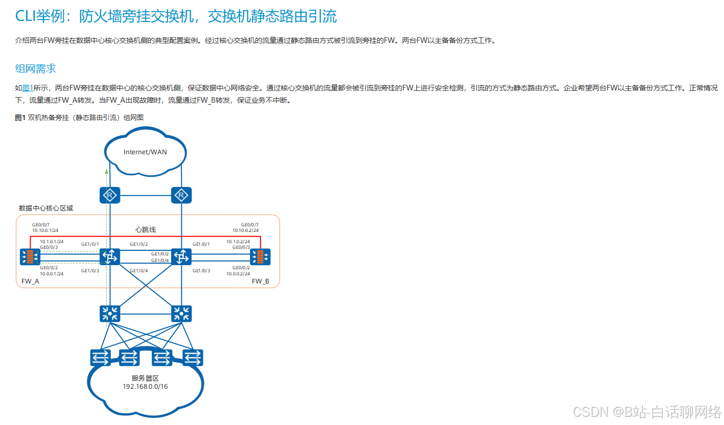
今天接了一个组网需求,课题是园区网络和通过MQC技术实现引流,那么一般来说,防火墙的防火墙引流都是通过上下行vrrp,交换机通过vpn实例来实现。
今天我的方案的在交换机上通过策略路由(PBR)的方式来实现。而这种配置方式则需要MQC模版来完成。
那么MQC是什么?
MQC(Modular QoS CLI,模块化QoS命令行)模板是一种结构化配置方法,用于灵活定义和实施流量管理策略(如QoS、流量过滤、重标记等)
流分类(Traffic Classifier)流行为(Traffic Behavior)流策略(Traffic Policy)就是三要素
所以题目中园区网络和通过MQC技术实现引流,就是说要用以上内容实现分流效果

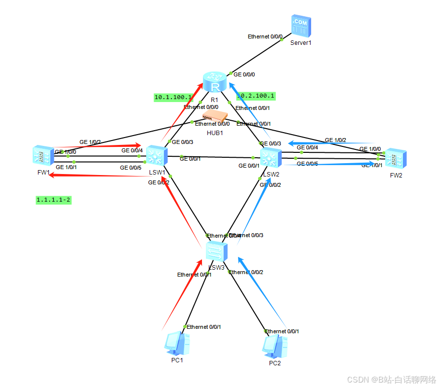
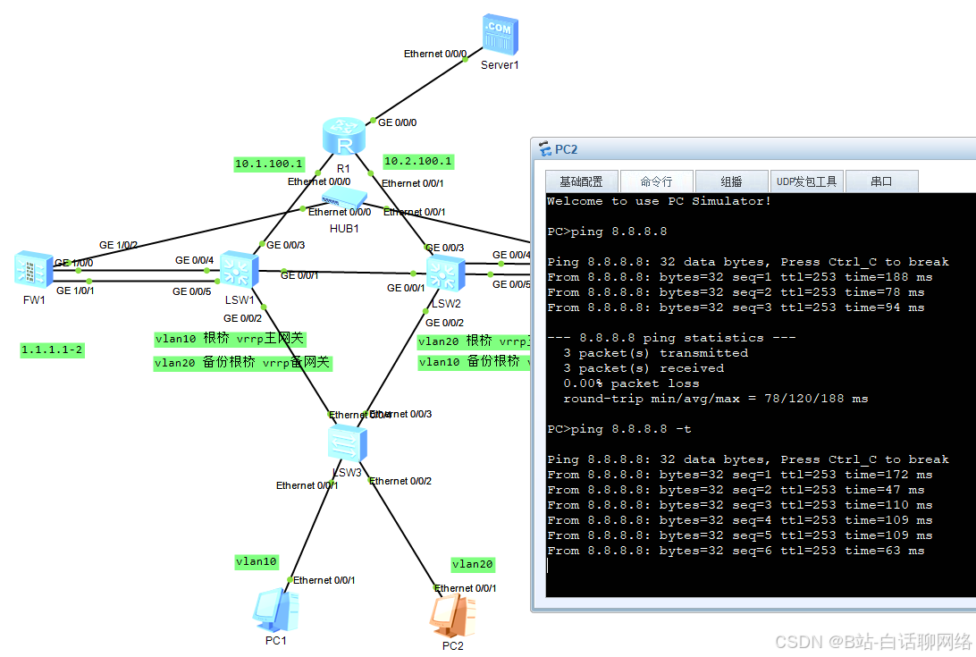
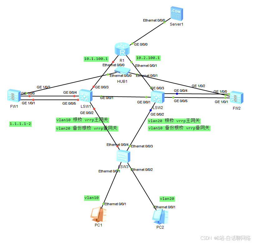
该实验中,二层用的mstp进行路径控制,vlan10走左,vlan20走右,vrrp也是负载模式
然后在交换机上通过MQC来将各自来的主流量引到防火墙,进行流量的清洗
配置如下
sysname sw3
#
undo info-center enable
#
vlan batch 10 20
#
stp region-configuration
 region-name huawei
 instance 1 vlan 10
 instance 2 vlan 20
 active region-configuration
#
interface Ethernet0/0/1
 port link-type access
 port default vlan 10
#
interface Ethernet0/0/2
 port link-type access
 port default vlan 20
#
interface Ethernet0/0/3
 port link-type trunk
 port trunk allow-pass vlan 10 20
#
interface Ethernet0/0/4
 port link-type trunk
 port trunk allow-pass vlan 10 20
核心交换中值得注意的就是mqc模版是在内网口调用,这样匹配到的流量直接通过流动作就扔到了下一跳所在的防火墙上,通过防火墙的安全策略进行匹配和内网安全等进行流量清洗。
sysname sw1
#
undo info-center enable
#
vlan batch 10 20 100 to 102
#
stp instance 1 root primary
stp instance 2 root secondary
#
stp region-configuration
 region-name huawei
 instance 1 vlan 10
 instance 2 vlan 20
 active region-configuration
#
acl number 3000
 rule 10 permit ip source 192.168.0.0 0.0.255.255
#
traffic classifier 1 operator and
 if-match acl 3000
#
traffic behavior 1
 redirect ip-nexthop 10.1.102.1
#
traffic policy 1
 classifier 1 behavior 1
#
interface Vlanif10
 ip address 192.168.10.252 255.255.255.0
 vrrp vrid 10 virtual-ip 192.168.10.254
 vrrp vrid 10 priority 120
 vrrp vrid 10 track interface GigabitEthernet0/0/3 reduced 30
#
interface Vlanif20
 ip address 192.168.20.252 255.255.255.0
 vrrp vrid 20 virtual-ip 192.168.20.254
#
interface Vlanif100
 ip address 10.1.100.2 255.255.255.252
#
interface Vlanif101
 ip address 10.1.101.2 255.255.255.252
#
interface Vlanif102
 ip address 10.1.102.2 255.255.255.252
#
interface GigabitEthernet0/0/1
 port link-type trunk
 port trunk allow-pass vlan 10 20
#
interface GigabitEthernet0/0/2
 port link-type trunk
 port trunk allow-pass vlan 10 20
 traffic-policy 1 inbound
#
interface GigabitEthernet0/0/3
 port link-type access
 port default vlan 100
#
interface GigabitEthernet0/0/4
 port link-type access
 port default vlan 101
#
interface GigabitEthernet0/0/5
 port link-type access
 port default vlan 102
#
ospf 1
 area 0.0.0.0
  network 10.1.100.0 0.0.0.3
  network 192.168.0.0 0.0.255.255
sysname sw2
#
undo info-center enable
#
vlan batch 10 20 100 201 to 202
#
stp instance 1 root secondary
stp instance 2 root primary
#
stp region-configuration
region-name huawei
instance 1 vlan 10
instance 2 vlan 20
active region-configuration
#
acl number 3000
rule 10 permit ip source 192.168.0.0 0.0.255.255
#
traffic classifier 1 operator and
if-match acl 3000
#
traffic behavior 1
redirect ip-nexthop 10.1.202.1
#
traffic policy 1
classifier 1 behavior 1
#
interface Vlanif10
ip address 192.168.10.253 255.255.255.0
vrrp vrid 10 virtual-ip 192.168.10.254
#
interface Vlanif20
ip address 192.168.20.253 255.255.255.0
vrrp vrid 20 virtual-ip 192.168.20.254
vrrp vrid 20 priority 120
#
interface Vlanif100
ip address 10.2.100.2 255.255.255.252
#
interface Vlanif201
ip address 10.1.201.2 255.255.255.252
#
interface Vlanif202
ip address 10.1.202.2 255.255.255.252
#
interface GigabitEthernet0/0/1
port link-type trunk
port trunk allow-pass vlan 10 20
#
interface GigabitEthernet0/0/2
port link-type trunk
port trunk allow-pass vlan 10 20
traffic-policy 1 inbound
#
interface GigabitEthernet0/0/3
port link-type access
port default vlan 100
#
interface GigabitEthernet0/0/4
port link-type access
port default vlan 201
#
interface GigabitEthernet0/0/5
port link-type access
port default vlan 202
#
ospf 1
area 0.0.0.0
network 10.2.100.0 0.0.0.3
network 192.168.0.0 0.0.255.255防火墙配置
sysname FW
#
 hrp enable
 hrp interface GigabitEthernet1/0/2 remote 1.1.1.2
 hrp standby config enable
#
interface GigabitEthernet1/0/0
 ip address 10.1.101.1 255.255.255.252
 service-manage ping permit
#
interface GigabitEthernet1/0/1
 ip address 10.1.102.1 255.255.255.252
 service-manage ping permit
#
interface GigabitEthernet1/0/2
 ip address 1.1.1.1 255.255.255.252
#
firewall zone untrust
 add interface GigabitEthernet1/0/0
#
firewall zone dmz
 add interface GigabitEthernet1/0/1
 add interface GigabitEthernet1/0/2
#
ip route-static 0.0.0.0 0.0.0.0 10.1.101.2
#
security-policy
 rule name 1
  source-zone dmz
  source-zone untrust
  destination-zone dmz
  destination-zone untrust
  action permit
sysname FW
#
hrp enable
hrp interface GigabitEthernet1/0/2 remote 1.1.1.1
hrp standby config enable
#
interface GigabitEthernet1/0/0
ip address 10.1.201.1 255.255.255.252
service-manage ping permit
#
interface GigabitEthernet1/0/1
ip address 10.1.202.1 255.255.255.252
service-manage ping permit
#
interface GigabitEthernet1/0/2
ip address 1.1.1.2 255.255.255.252
#
firewall zone untrust
add interface GigabitEthernet1/0/0
#
firewall zone dmz
add interface GigabitEthernet1/0/1
add interface GigabitEthernet1/0/2
#
ip route-static 0.0.0.0 0.0.0.0 10.1.201.2
#
security-policy
rule name 1
source-zone dmz
source-zone untrust
destination-zone dmz
destination-zone untrust
action permit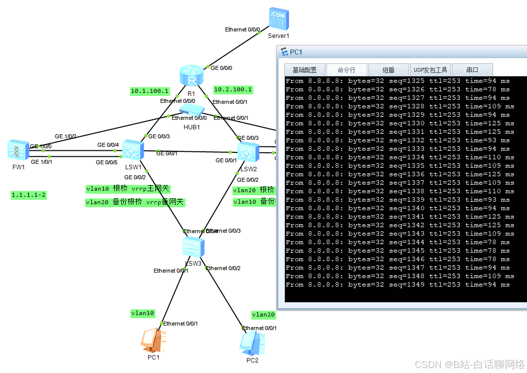
防火墙1上映射了vlan10的用户访问服务器
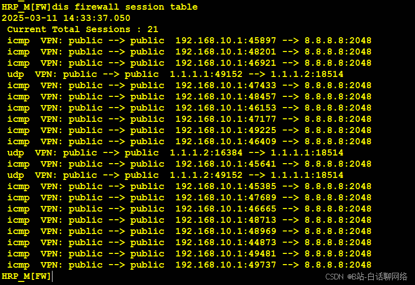
防火墙2上映射了vlan20的用户访问服务器
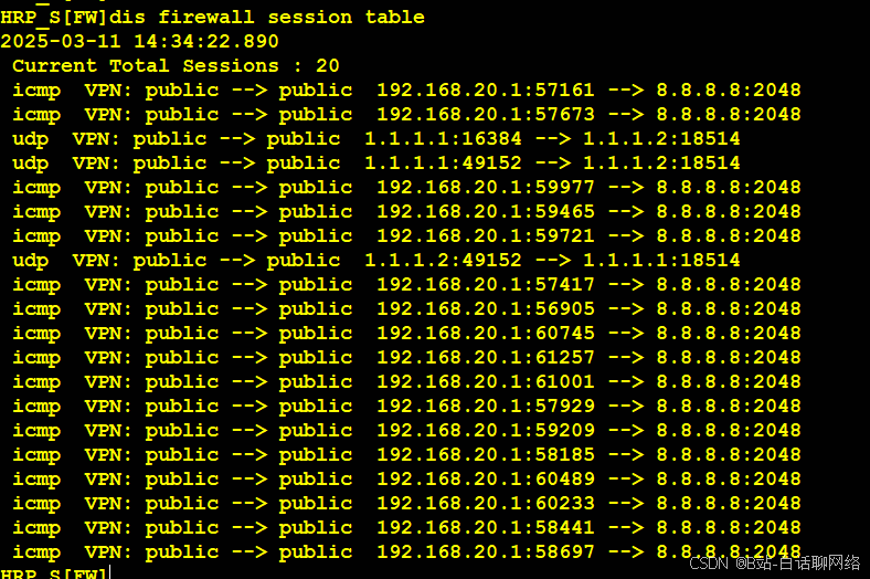
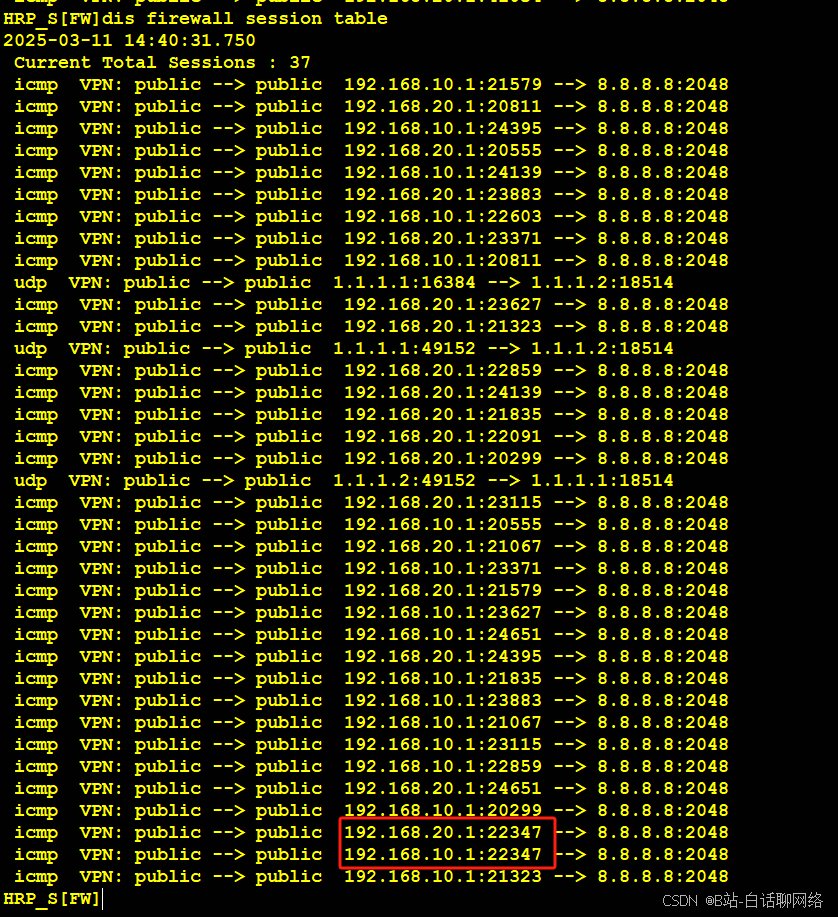
此时关闭核心交换机1的所以接口,不建议直接关设备(因为这是模拟器)
丢一部分包,为什么丢包未知,当核心1中断后,sw3的stp状态已经切换,sw2的vrrp已经切换,不应该会不通,唯一的可能就是vrrp的重新发送免费arp的延迟导致
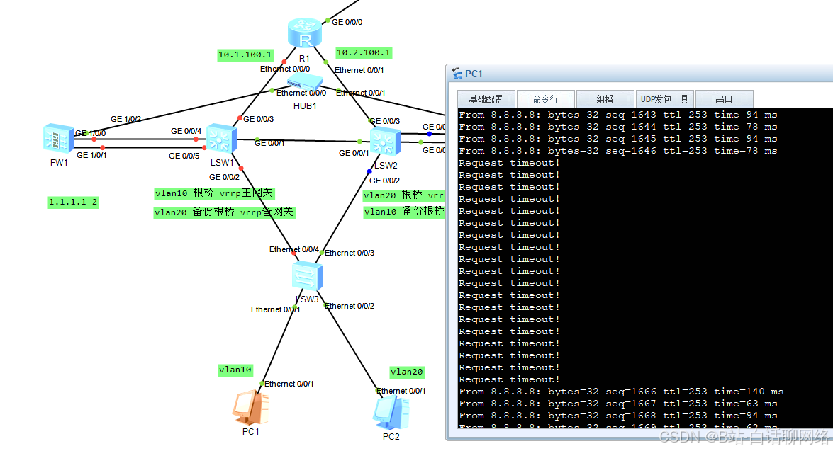
最终流量经过防火墙2
以上就是本期防火墙双击热备(负载模式的旁挂引流方式)


 4104
4104

 被折叠的 条评论
为什么被折叠?
被折叠的 条评论
为什么被折叠?
 到【灌水乐园】发言


