


【高通SDM660平台】Camera 驱动 Bringup
参考链接:【高通SDM660平台】(1) --- Camera 驱动 Bringup Guide_CielleeX的博客-CSDN博客
一、Kernel 代码移植
1. DTS 文件配置
dts 文件目录:
高通SDM660平台代码中,arm64 与 arm 走的是同一个目录文件,
kernel\msm-4.4\arch\arm64\boot\dts\qcom这个目录其实是 \kernel\msm-4.4\arch\arm\boot\dts\qcom的软链接。
Camera 相关的 dts 文件:
@ kernel\msm-4.4\arch\arm64\boot\dts\qcom\sdm660.dtsi
@ kernel\msm-4.4\arch\arm64\boot\dts\qcom\sdm660-camera.dtsi
@ kernel\msm-4.4\arch\arm64\boot\dts\qcom\sdm660-pinctrl.dtsi
@ kernel\msm-4.4\arch\arm64\boot\dts\qcom\sdm660-camera-sensor-mtp.dtsi
1.1 sdm660.dtsi
在该文件中,主要功能如下:
- 引入 sdm660-camera.dtsi 文件
- 配置 camera_focus 和 camera_snapshot 对应的 GPIO 及 上报的 keycode。
@ \kernel\msm-4.4\arch\arm\boot\dts\qcom\sdm660.dtsi
// 1. 引入 sdm660-camera.dtsi
#include "sdm660-camera.dtsi"

// 2. 配置 camera_focus 和 camera_snapshot GPIO 及对应的 keycode。
&soc {
	gpio_keys {
		status = "okay";
		compatible = "gpio-keys";
		input-name = "gpio-keys";
		pinctrl-names = "tlmm_gpio_key_active","tlmm_gpio_key_suspend";
		pinctrl-0 = <&gpio_key_active>;
		pinctrl-1 = <&gpio_key_suspend>;

		camera_focus {
			label = "camera_focus";
			gpios = <&tlmm 64 0x1>;
			linux,input-type = <1>;
			linux,code = <0x210>;
			debounce-interval = <15>;
		};
		camera_snapshot {
			label = "camera_snapshot";
			gpios = <&tlmm 113 0x1>;
			linux,input-type = <1>;
			linux,code = <0x2fe>;
			debounce-interval = <15>;
		};
	};
};
1.2 sdm660-camera.dtsi
在 sdm660-camera.dtsi 中主要是配置了平台相关的Camera 底层硬件相关的配置,比如 CSI,CS。
如无特殊需求,一般不会修改此处的代码。
部分代码及对应的解释如下:
各参数解析详见:
@ \kernel\msm-4.4\Documentation\devicetree\bindings\media\video\msm-csid.txt
@ \kernel\msm-4.4\Documentation\devicetree\bindings\media\video\msm-csi-phy.txt

&soc {
	qcom,csiphy@c824000 {									// CSI 总线映射的寄存器地址
		cell-index = <0>;									// CSI 硬件总线索引号 0
		compatible = "qcom,csiphy-v3.5", "qcom,csiphy";		// compatible = “a厂商,p产品”, “标准bbb类型设备”。
		// 那么linux kernel可能首先使用“a厂商,p产品”来匹配适合的driver,
		// 如果没有匹配到,那么使用字符串“标准bbb类型设备”来继续寻找适合的driver。

		reg = <0xc824000 0x1000>,<0xca00120 0x4>;			// 使用的寄存器地址 及 长度
		reg-names = "csiphy", "csiphy_clk_mux";				// cisphy 寄存器地址为 0xc824000, 长度为 0x1000
															// csiphy_clk_mux 寄存器地址为 0xca00120,长度为 0x4
		interrupts = <0 78 0>;	// interrupt的格式是<type, interrupt number, trigger type>, 详见《(扩展1) interrupts 中断节点解析》
		interrupt-names = "csiphy";	 // 中断name,可通过 cat /proc/interrupts 获取
		gdscr-supply = <&gdsc_camss_top>;
		bimc_smmu-supply = <&gdsc_bimc_smmu>;
		qcom,cam-vreg-name = "gdscr", "bimc_smmu";		// voltage regulators 和 name
		clocks = <&clock_rpmcc MMSSNOC_AXI_CLK>,		// clocks 和 name
			<&clock_mmss MMSS_MNOC_AHB_CLK>,
			<&clock_mmss MMSS_BIMC_SMMU_AHB_CLK>,
			<&clock_mmss MMSS_BIMC_SMMU_AXI_CLK>,
			<&clock_mmss MMSS_CAMSS_AHB_CLK>,
			<&clock_mmss MMSS_CAMSS_TOP_AHB_CLK>,
			<&clock_mmss CSI0_CLK_SRC>,
			<&clock_mmss MMSS_CAMSS_CSI0_CLK>,
			<&clock_mmss MMSS_CAMSS_CPHY_CSID0_CLK>,
			<&clock_mmss CSI0PHYTIMER_CLK_SRC>,
			<&clock_mmss MMSS_CAMSS_CSI0PHYTIMER_CLK>,
			<&clock_mmss MMSS_CAMSS_ISPIF_AHB_CLK>,
			<&clock_mmss CSIPHY_CLK_SRC>,
			<&clock_mmss MMSS_CAMSS_CSIPHY0_CLK>,
			<&clock_mmss MMSS_CSIPHY_AHB2CRIF_CLK>;
		clock-names = "mmssnoc_axi", "mnoc_ahb",
			"bmic_smmu_ahb", "bmic_smmu_axi",
			"camss_ahb_clk", "camss_top_ahb_clk",
			"csi_src_clk", "csi_clk", "cphy_csid_clk",
			"csiphy_timer_src_clk", "csiphy_timer_clk",
			"camss_ispif_ahb_clk", "csiphy_clk_src", "csiphy_clk",
			"csiphy_ahb2crif";
		qcom,clock-rates = <0 0 0 0 0 0 310000000 0 0 269333333 0 0 200000000 0 0>;  // 上面对应所有clock 的速率
		status = "ok";
	};

	qcom,csiphy@c825000 {
		cell-index = <1>;								// CSI 硬件总线索引号 1
		compatible = "qcom,csiphy-v3.5", "qcom,csiphy";
		reg = <0xc825000 0x1000>, <0xca00124 0x4>;
		reg-names = "csiphy", "csiphy_clk_mux";		// cisphy 寄存器地址为 0xc825000, 长度为 0x1000
													// csiphy_clk_mux 寄存器地址为 0xca00124 ,长度为 0x4
		interrupts = <0 79 0>;
		interrupt-names = "csiphy";
		...... // 此处省略一大段代码,内容和前面 CSI 0 一样,配置clk 及其速率
	};
1.3 sdm660-camera-sensor-mtp.dtsi
文件 sdm660-pinctrl.dtsi和 sdm660-camera-sensor-mtp.dtsi是在 sdm660-mtp.dtsi中被包含的。
@ \kernel\msm-4.4\arch\arm\boot\dts\qcom\sdm660-mtp.dtsi

#include "sdm660-pinctrl.dtsi"
#include "sdm660-camera-sensor-mtp.dtsi"
sdm660-camera-sensor-mtp.dtsi是kernel camera 重点要配置的文件
其中包括了 camera 闪光灯的配置,avdd/dovdd/dvdd/vaf 等电压的配置,camera 马达的配置 ,eeprom的配置,camera sensor的配置。
1.3.1 Camera Sensor DTS配置
@ \kernel\msm-4.4\arch\arm\boot\dts\qcom\sdm660-camera-sensor-mtp.dtsi
@ \kernel\msm-4.4\Documentation\devicetree\bindings\media\video\msm-cci.txt

&cci {
	qcom,camera@0 {
		cell-index = <0>;			// Camera索引号 0,此处注意不要重复了
		compatible = "qcom,camera";
		reg = <0x0>;				// 和索引号一样
		qcom,csiphy-sd-index = <0>;	// 使用 CSI 0,具体根据硬件决定,一般来说, 0:后摄, 1:前摄
		qcom,csid-sd-index = <0>;	// 使用 CSI 0
		qcom,mount-angle = <90>;	// Sensor 成像方向与主板的角度,camear旋转角度
		qcom,led-flash-src = <&led_flash0>; // 闪光灯,使用 led_flash0
		qcom,actuator-src = <&actuator0>; 	// 马达,使用 actuator0
		qcom,ois-src = <&ois0>;				// 是否支持 光学防抖
		qcom,eeprom-src = <&eeprom1>;		// eeprom 1
		cam_vio-supply = <&pm660_l11>;						// IO voltage      	IO口电压 VDDIO 数字 IO 电源主要给 I2C 部分供电;
		cam_vana-supply = <&cam_avdd_gpio_regulator>;		// analog voltage	模拟电压 AVDD 模拟供电,主要给感光区和 ADC 部分供电;
		cam_vdig-supply = <&cam_rear_dvdd_gpio_regulator>;	// digital voltage	数字电压DVDD 数字供电,主要给 ISP 供电
		cam_vaf-supply = <&cam_vaf_gpio_regulator>;			// AF voltage		Camera 自动对焦马达的供电
		cam_v_custom1-supply = <&cam_dovdd_gpio_regulator>;
		qcom,cam-vreg-name = "cam_vio", "cam_vana", "cam_vdig", "cam_vaf","cam_v_custom1";   // 供电配置 及对应的 电压,详见下
		qcom,cam-vreg-min-voltage = <1780000 0 0 0 0>;
		qcom,cam-vreg-max-voltage = <1950000 0 0 0 0>;
		qcom,cam-vreg-op-mode = <105000 0 0 0 0>;
		qcom,gpio-no-mux = <0>;		// 1:表示 gpio mux 不可用   0:表示可用
		pinctrl-names = "cam_default", "cam_suspend";	// Camera gpio clk 和 reset gpio 配置
		pinctrl-0 = <&cam_sensor_mclk0_active &cam_sensor_rear_active>;
		pinctrl-1 = <&cam_sensor_mclk0_suspend &cam_sensor_rear_suspend>;
		gpios = <&tlmm 32 0>, <&tlmm 46 0>;
		qcom,gpio-reset = <1>;
		qcom,gpio-req-tbl-num = <0 1>;
		qcom,gpio-req-tbl-flags = <1 0>;
		qcom,gpio-req-tbl-label = "CAMIF_MCLK0", "CAM_RESET0";
		qcom,sensor-position = <0>;		// 1:前置   0:后置
		qcom,sensor-mode = <0>;
			===>{  @ \kernel\msm-4.4\Documentation\devicetree\bindings\media\video\msm-cci.txt
			- qcom,sensor-mode : should contain sensor mode supported
			    - 0 -> back camera 2D
			    - 1 -> front camera 2D
			    - 2 -> back camera 3D
			    - 3 -> back camera int 3D
			}
		qcom,cci-master = <0>;		// I2C 0
		status = "ok";
		clocks = <&clock_mmss MCLK0_CLK_SRC>, <&clock_mmss MMSS_CAMSS_MCLK0_CLK>;
		clock-names = "cam_src_clk", "cam_clk";
		qcom,clock-rates = <24000000 0>;	// clock rate in Hz

//- qcom,sensor-type : should contain format of data that sensor streams
//    - 0 -> bayer format
//    - 1 -> yuv format

	};

	qcom,camera@1 {
		cell-index = <1>;		// Camera索引号 1,此处注意不要重复了
		compatible = "qcom,camera";
		reg = <0x1>;
		qcom,csiphy-sd-index = <1>;
		qcom,csid-sd-index = <1>;
		qcom,mount-angle = <90>;
		qcom,actuator-src = <&actuator1>;
		qcom,eeprom-src = <&eeprom1>;
		cam_vio-supply = <&cam_dovdd_gpio_regulator>;
		cam_vana-supply = <&cam_avdd_gpio_regulator>;
		cam_vdig-supply = <&cam_rear_dvdd_gpio_regulator>;
		cam_vaf-supply = <&cam_vaf_gpio_regulator>;
		qcom,cam-vreg-name = "cam_vio", "cam_vana", "cam_vdig", "cam_vaf";
		qcom,cam-vreg-min-voltage = <0 0 0 0>;
		qcom,cam-vreg-max-voltage = <0 0 0 0>;
		qcom,cam-vreg-op-mode = <105000 0 0 0>;
		qcom,gpio-no-mux = <0>;
		pinctrl-names = "cam_default", "cam_suspend";
		pinctrl-0 = <&cam_sensor_mclk2_active &cam_sensor_rear2_active>;
		pinctrl-1 = <&cam_sensor_mclk2_suspend &cam_sensor_rear2_suspend>;
		gpios = <&tlmm 34 0>, <&tlmm 48 0>;
		qcom,gpio-reset = <1>;
		qcom,gpio-req-tbl-num = <0 1>;
		qcom,gpio-req-tbl-flags = <1 0>;
		qcom,gpio-req-tbl-label = "CAMIF_MCLK", "CAM_RESET";
		qcom,sensor-position = <0>;		// 1:前置   0:后置
		qcom,sensor-mode = <0>;			// 0 -> back camera 2D
		qcom,cci-master = <1>;			// I2C 1
		status = "ok";
		clocks = <&clock_mmss MCLK2_CLK_SRC>, <&clock_mmss MMSS_CAMSS_MCLK2_CLK>;
		clock-names = "cam_src_clk", "cam_clk";
		qcom,clock-rates = <24000000 0>;
	};

	qcom,camera@2 {
		cell-index = <2>;			// Camera索引号 2,此处注意不要重复了
		compatible = "qcom,camera";
		reg = <0x02>;
		qcom,csiphy-sd-index = <2>;
		qcom,csid-sd-index = <2>;
		qcom,mount-angle = <270>;
		//qcom,actuator-src = <&actuator2>;		// 前报不需要马达,所以此处不用配置马达 ,同样下面也不用配置 af voltage
		qcom,eeprom-src = <&eeprom2>;
		cam_vio-supply = <&pm660_l11>;
		cam_vana-supply = <&cam_avdd_gpio_regulator>;
		cam_vdig-supply = <&cam_dvdd_gpio_regulator>;
		qcom,cam-vreg-name = "cam_vio", "cam_vana", "cam_vdig";
		qcom,cam-vreg-min-voltage = <1780000 0 0>;
		qcom,cam-vreg-max-voltage = <1950000 0 0>;
		qcom,cam-vreg-op-mode = <105000 0 0>;
		qcom,gpio-no-mux = <0>;
		pinctrl-names = "cam_default", "cam_suspend";
		pinctrl-0 = <&cam_sensor_mclk1_active &cam_sensor_front_active>;
		pinctrl-1 = <&cam_sensor_mclk1_suspend &cam_sensor_front_suspend>;
		gpios = <&tlmm 33 0>, <&tlmm 47 0>;
		qcom,gpio-reset = <1>;
		qcom,gpio-req-tbl-num = <0 1>;
		qcom,gpio-req-tbl-flags = <1 0>;
		qcom,gpio-req-tbl-label = "CAMIF_MCLK2", "CAM_RESET2";
		qcom,sensor-position = <1>;			// 1:前置   0:后置
		qcom,sensor-mode = <1>;				// 1 -> front camera 2D
		qcom,cci-master = <1>;				// I2C 1
		status = "ok";
		clocks = <&clock_mmss MCLK1_CLK_SRC>, <&clock_mmss MMSS_CAMSS_MCLK1_CLK>;
		clock-names = "cam_src_clk", "cam_clk";
		qcom,clock-rates = <24000000 0>;
	};
}
1.3.2 Camera 供电DTS配置(avdd/dovdd/dvdd/vaf)
Camera 供电配置要根据具体的硬件来配置,
如果走的是 pm 电源则配置如cam_vio-supply = <&pm660_l11>;
如果走的是具体GPIO供电,则要做如下配置 ,调用时配置如cam_vana-supply = <&cam_avdd_gpio_regulator>;
各GPIO 供电配置如下:
@ \kernel\msm-4.4\arch\arm\boot\dts\qcom\sdm660-camera-sensor-mtp.dtsi
&soc {
	cam_avdd_gpio_regulator: cam_avdd_fixed_regulator {
		compatible = "regulator-fixed";
		regulator-name = "cam_avdd_gpio_regulator";
		regulator-min-microvolt = <3600000>;
		regulator-max-microvolt = <3600000>;
		enable-active-high;
		gpio = <&tlmm 51 0>;			// 使用 CPU的 GPIO 51 ,供电 3.6v
		vin-supply = <&pm660l_bob>;
	};

	cam_dovdd_gpio_regulator: cam_dovdd_fixed_regulator {
		compatible = "regulator-fixed";
		regulator-name = "cam_dovdd_gpio_regulator";
		regulator-min-microvolt = <3600000>;
		regulator-max-microvolt = <3600000>;
		enable-active-high;
		gpio = <&tlmm 0 0>;				// 使用 CPU的 GPIO 0 ,供电 3.6v
		vin-supply = <&pm660l_bob>;
	};

	cam_dvdd_gpio_regulator: cam_dvdd_fixed_regulator {
		compatible = "regulator-fixed";
		regulator-name = "cam_dvdd_gpio_regulator";
		regulator-min-microvolt = <3600000>;
		regulator-max-microvolt = <3600000>;
		enable-active-high;
		gpio = <&pm660l_gpios 3 0>;			// 使用 PM660L的 gpio 3 ,供电 3.6v
		vin-supply = <&pm660l_bob>;
	};

	cam_rear_dvdd_gpio_regulator: cam_rear_dvdd_fixed_regulator {
		compatible = "regulator-fixed";
		regulator-name = "cam_rear_dvdd_gpio_regulator";
		regulator-min-microvolt = <3600000>;
		regulator-max-microvolt = <3600000>;
		enable-active-high;
		gpio = <&pm660l_gpios 4 0>;			// 使用 PM660L的 gpio 4 ,供电 3.6v
		vin-supply = <&pm660l_bob>;
	};

	cam_vaf_gpio_regulator:cam_vaf_fixed_regulator {
		compatible = "regulator-fixed";
		regulator-name = "cam_vaf_gpio_regulator";
		regulator-min-microvolt = <3600000>;
		regulator-max-microvolt = <3600000>;
		enable-active-high;
		gpio = <&tlmm 50 0>;				// 使用 CPU的 gpio 50 ,供电 3.6v
		vin-supply = <&pm660l_bob>;
	};
};
1.3.3 Camera 闪光灯DTS配置
@ \kernel\msm-4.4\arch\arm\boot\dts\qcom\sdm660-camera-sensor-mtp.dtsi
&soc {
	led_flash0: qcom,camera-flash@0 {
		cell-index = <0>;					// 闪光灯配置索引 0
		compatible = "qcom,camera-flash";
		// 如下: 如果两颗灯的话,则配置对应的两个供电,如果是一颗灯的主话,则配置一个供电
		qcom,flash-source = <&pm660l_flash0 &pm660l_flash1>;//闪光灯供电配置
		qcom,torch-source = <&pm660l_torch0 &pm660l_torch1>;//手电筒供电配置
		qcom,switch-source = <&pm660l_switch0>;
		status = "ok";
	};

	led_flash1: qcom,camera-flash@1 {
		cell-index = <1>;					// 闪光灯配置索引 1
		compatible = "qcom,camera-flash";
		qcom,flash-source = <&pm660l_flash2>; //闪光灯供电配置
		qcom,torch-source = <&pm660l_torch2>; //手电筒供电配置
		qcom,switch-source = <&pm660l_switch1>;
		status = "ok";
	};
上述的相关电源配置均在 msm-pm660l.dtsi文件中
@ \kernel\msm-4.4\arch\arm\boot\dts\qcom\msm-pm660l.dtsi

		flash_led: qcom,leds@d300 {
			compatible = "qcom,qpnp-flash-led-v2";
			reg = <0xd300 0x100>;
			label = "flash";
			interrupts = <0x3 0xd3 0x0 IRQ_TYPE_EDGE_RISING>,
					<0x3 0xd3 0x3 IRQ_TYPE_EDGE_RISING>,
					<0x3 0xd3 0x4 IRQ_TYPE_EDGE_RISING>;
			interrupt-names = "led-fault-irq",
					"all-ramp-down-done-irq",
					"all-ramp-up-done-irq";
			qcom,hdrm-auto-mode;
			qcom,short-circuit-det;
			qcom,open-circuit-det;
			qcom,vph-droop-det;
			qcom,thermal-derate-en;
			qcom,thermal-derate-current = <200 500 1000>;
			qcom,isc-delay = <192>;
			qcom,pmic-revid = <&pm660l_revid>;

			pm660l_flash0: qcom,flash_0 {
				label = "flash";
				qcom,led-name = "led:flash_0";
				qcom,max-current = <1500>;	// 最大电流 1.5A
				qcom,default-led-trigger = "flash0_trigger";
				qcom,id = <0>;				// flash0
				qcom,current-ma = <1000>;
				qcom,duration-ms = <1280>;
				qcom,ires-ua = <12500>;
				qcom,hdrm-voltage-mv = <325>;
				qcom,hdrm-vol-hi-lo-win-mv = <100>;
			};

			pm660l_flash1: qcom,flash_1 {
				label = "flash";
				qcom,led-name = "led:flash_1";
				qcom,max-current = <1500>;
				qcom,default-led-trigger = "flash1_trigger";
				qcom,id = <1>;
				qcom,current-ma = <1000>;
				qcom,duration-ms = <1280>;
				qcom,ires-ua = <12500>;
				qcom,hdrm-voltage-mv = <325>;
				qcom,hdrm-vol-hi-lo-win-mv = <100>;
			};

			pm660l_flash2: qcom,flash_2 {
				label = "flash";
				qcom,led-name = "led:flash_2";
				qcom,max-current = <750>;
				qcom,default-led-trigger = "flash2_trigger";
				qcom,id = <2>;
				qcom,current-ma = <500>;
				qcom,duration-ms = <1280>;
				qcom,ires-ua = <12500>;
				qcom,hdrm-voltage-mv = <325>;
				qcom,hdrm-vol-hi-lo-win-mv = <100>;
			};
			pm660l_torch0: qcom,torch_0 {
				label = "torch";
				qcom,led-name = "led:torch_0";
				qcom,max-current = <500>;
				qcom,default-led-trigger = "torch0_trigger";
				qcom,id = <0>;
				qcom,current-ma = <300>;
				qcom,ires-ua = <12500>;
				qcom,hdrm-voltage-mv = <325>;
				qcom,hdrm-vol-hi-lo-win-mv = <100>;
			};
			......
			pm660l_switch0: qcom,led_switch_0 {
				label = "switch";
				qcom,led-name = "led:switch_0";
				qcom,led-mask = <3>;
				qcom,default-led-trigger = "switch0_trigger";
			};
		};
1.3.4 Camera 马达DTS配置
&cci {
	actuator0: qcom,actuator@0 {
		cell-index = <0>;
		reg = <0x0>;
		compatible = "qcom,actuator";
		qcom,cci-master = <0>;		// 马达使用的 i2c master , I2C 0
		cam_vaf-supply = <&cam_vaf_gpio_regulator>;	// 马达供电
		qcom,cam-vreg-name = "cam_vaf";
		qcom,cam-vreg-min-voltage = <3300000>;
		qcom,cam-vreg-max-voltage = <3600000>;
		qcom,cam-vreg-op-mode = <100000>;
	};

	actuator1: qcom,actuator@1 {
		cell-index = <1>;
		reg = <0x1>;
		compatible = "qcom,actuator";
		qcom,cci-master = <1>;		// 马达使用的 i2c master , I2C 1
		cam_vaf-supply = <&cam_vaf_gpio_regulator>;
		qcom,cam-vreg-name = "cam_vaf";
		qcom,cam-vreg-min-voltage = <3300000>;
		qcom,cam-vreg-max-voltage = <3600000>;
		qcom,cam-vreg-op-mode = <100000>;
	};
1.3.5 Camera 光学防抖 OSI DTS配置
ois0: qcom,ois@0 {
		cell-index = <0>;
		reg = <0x0>;
		compatible = "qcom,ois";
		qcom,cci-master = <0>;	// 使用 I2C 0
		gpios = <&tlmm 50 0>;	// GPIO 50
		qcom,gpio-vaf = <0>;
		qcom,gpio-req-tbl-num = <0>;
		qcom,gpio-req-tbl-flags = <0>;
		qcom,gpio-req-tbl-label = "CAM_VAF";
		pinctrl-names = "cam_default", "cam_suspend";
		pinctrl-0 = <&cam_actuator_vaf_active>;
		pinctrl-1 = <&cam_actuator_vaf_suspend>;
		status = "disabled";
	};
1.3.6 Camera eeprom DTS配置
eeprom0: qcom,eeprom@0 {
		cell-index = <0>;
		reg = <0>;
		compatible = "qcom,eeprom";
		cam_vio-supply = <&pm660_l11>;
		cam_vana-supply = <&cam_avdd_gpio_regulator>;
		cam_vdig-supply = <&cam_rear_dvdd_gpio_regulator>;
		cam_vaf-supply = <&pm660l_l8>;
		qcom,cam-vreg-name = "cam_vio", "cam_vana", "cam_vdig", "cam_vaf";
		qcom,cam-vreg-min-voltage = <1780000 0 0 2800000>;
		qcom,cam-vreg-max-voltage = <1950000 0 0 3400000>;
		qcom,cam-vreg-op-mode = <105000 0 0 100000>;
		qcom,gpio-no-mux = <0>;
		pinctrl-names = "cam_default", "cam_suspend";
		pinctrl-0 = <&cam_sensor_mclk0_active &cam_sensor_rear_active>;
		pinctrl-1 = <&cam_sensor_mclk0_suspend	&cam_sensor_rear_suspend>;
		gpios = <&tlmm 32 0>, <&tlmm 46 0>;
		qcom,gpio-reset = <1>;
		qcom,gpio-req-tbl-num = <0 1>;
		qcom,gpio-req-tbl-flags = <1 0>;
		qcom,gpio-req-tbl-label = "CAMIF_MCLK0", "CAM_RESET0";
		qcom,sensor-position = <0>;
		qcom,sensor-mode = <0>;
		qcom,cci-master = <0>;
		status = "ok";
		clocks = <&clock_mmss MCLK0_CLK_SRC>, <&clock_mmss MMSS_CAMSS_MCLK0_CLK>;
		clock-names = "cam_src_clk", "cam_clk";
		qcom,clock-rates = <24000000 0>;
	};
1.3.7 Camera PM660L GPIO DTS配置
前面我们使用到了两个 PM660L 的GPIO:gpio = <&pm660l_gpios 3 0>;gpio = <&pm660l_gpios 4 0>;
不同于 CPU的gpio ,其需要作单独配置,如下:
@\kernel\msm-4.4\arch\arm\boot\dts\qcom\sdm660-camera-sensor-mtp.dtsi
&pm660l_gpios {
	gpio@c300 { /* GPIO4 -CAMERA SENSOR 0 VDIG*/
		qcom,mode = <1>;                /* Output */
		qcom,pull = <5>;                /* No Pull */
		qcom,vin-sel = <0>;             /* VIN1 GPIO_LV */
		qcom,src-sel = <0>;             /* GPIO */
		qcom,invert = <0>;              /* Invert */
		qcom,master-en = <1>;           /* Enable GPIO */
		status = "ok";
	};

	gpio@c200 { /* GPIO3 -CAMERA SENSOR 2 VDIG*/
		qcom,mode = <1>;                /* Output */
		qcom,pull = <5>;                /* No Pull */
		qcom,vin-sel = <0>;             /* VIN1 GPIO_LV */
		qcom,src-sel = <0>;             /* GPIO */
		qcom,invert = <0>;              /* Invert */
		qcom,master-en = <1>;           /* Enable GPIO */
		status = "ok";
	};
};
1.4 sdm660-pinctrl.dtsi
在前面 中,有需要用到的gpio,出于电源管理的需求,需要在 pinctrl 中配置其active 和 suspend 对应的配置:
例如,GPIO 32 和 GPIO 46 以及 GPIO 50
在前边代码中,使用配置如下:
gpio 50:
		pinctrl-names = "cam_default", "cam_suspend";
		pinctrl-0 = <&cam_actuator_vaf_active>;
		pinctrl-1 = <&cam_actuator_vaf_suspend>;

GPIO 32 、GPIO 46:
		pinctrl-names = "cam_default", "cam_suspend";
		pinctrl-0 = <&cam_sensor_mclk0_active &cam_sensor_rear_active>;
		pinctrl-1 = <&cam_sensor_mclk0_suspend	&cam_sensor_rear_suspend>;
		gpios = <&tlmm 32 0>, <&tlmm 46 0>;
@ \kernel\msm-4.4\arch\arm\boot\dts\qcom\sdm660-pinctrl.dtsi
		cam_actuator_vaf_active: cam_actuator_vaf_active {
			/* ACTUATOR POWER */
			mux {
				pins = "gpio50";
				function = "gpio";
			};
			config {
				pins = "gpio50";
				bias-disable; /* No PULL */
				drive-strength = <2>; /* 2 MA */
			};
		};
		cam_actuator_vaf_suspend: cam_actuator_vaf_suspend {
			/* ACTUATOR POWER */
			mux {
				pins = "gpio50";
				function = "gpio";
			};
			config {
				pins = "gpio50";
				bias-pull-down; /* PULL DOWN */
				drive-strength = <2>; /* 2 MA */
			};
		};
		cam_sensor_mclk0_active: cam_sensor_mclk0_active {
			/* MCLK0 */
			mux {
				/* CLK */
				pins = "gpio32";
				function = "cam_mclk";
			};
			config {
				pins = "gpio32";
				bias-disable; /* No PULL */
				drive-strength = <2>; /* 2 MA */
			};
		};
		cam_sensor_mclk0_suspend: cam_sensor_mclk0_suspend {
			/* MCLK0 */
			mux {
				/* CLK */
				pins = "gpio32";
				function = "cam_mclk";
			};
			config {
				pins = "gpio32";
				bias-pull-down; /* PULL DOWN */
				drive-strength = <2>; /* 2 MA */
			};
		};
		cam_sensor_rear_active: cam_sensor_rear_active {
			/* RESET, STANDBY */
			mux {
				pins = "gpio46";
				function = "gpio";
			};
			config {
				pins = "gpio46";
				bias-disable; /* No PULL */
				drive-strength = <2>; /* 2 MA */
			};
		};
		cam_sensor_rear_suspend: cam_sensor_rear_suspend {
			/* RESET, STANDBY */
			mux {
				pins = "gpio46";
				function = "gpio";
			};
			config {
				pins = "gpio46";
				bias-disable; /* No PULL */
				drive-strength = <2>; /* 2 MA */
			};
		};
		cam_sensor_mclk1_active: cam_sensor_mclk1_active {
			/* MCLK1 */
			mux {
				/* CLK */
				pins = "gpio33";
				function = "cam_mclk";
			};
			config {
				pins = "gpio33";
				bias-disable; /* No PULL */
				drive-strength = <2>; /* 2 MA */
			};
		};
		cam_sensor_mclk1_suspend: cam_sensor_mclk1_suspend {
			/* MCLK1 */
			mux {
				/* CLK */
				pins = "gpio33";
				function = "cam_mclk";
			};
			config {
				pins = "gpio33";
				bias-pull-down; /* PULL DOWN */
				drive-strength = <2>; /* 2 MA */
			};
		};
		cam_sensor_rear2_active: cam_sensor_rear2_active {
			/* RESET, STANDBY */
			mux {
				pins = "gpio48";
				function = "gpio";
			};
			config {
				pins = "gpio48";
				bias-disable; /* No PULL */
				drive-strength = <2>; /* 2 MA */
			};
		};
		cam_sensor_rear2_suspend: cam_sensor_rear2_suspend {
			/* RESET, STANDBY */
			mux {
				pins = "gpio48";
				function = "gpio";
			};
			config {
				pins = "gpio48";
				bias-disable; /* No PULL */
				drive-strength = <2>; /* 2 MA */
			};
		};
		cam_sensor_mclk2_active: cam_sensor_mclk2_active {
			/* MCLK1 */
			mux {
				/* CLK */
				pins = "gpio34";
				function = "cam_mclk";
			};
			config {
				pins = "gpio34";
				bias-disable; /* No PULL */
				drive-strength = <2>; /* 2 MA */
			};
		};
		cam_sensor_mclk2_suspend: cam_sensor_mclk2_suspend {
			/* MCLK1 */
			mux {
				/* CLK */
				pins = "gpio34";
				function = "cam_mclk";
			};
			config {
				pins = "gpio34";
				bias-pull-down; /* PULL DOWN */
				drive-strength = <2>; /* 2 MA */
			};
		};
		cam_sensor_front_active: cam_sensor_front_active {
			/* RESET  VANA*/
			mux {
				pins = "gpio47";
				function = "gpio";
			};
			config {
				pins = "gpio47";
				bias-disable; /* No PULL */
				drive-strength = <2>; /* 2 MA */
			};
		};
		cam_sensor_front_suspend: cam_sensor_front_suspend {
			/* RESET */
			mux {
				pins = "gpio47";
				function = "gpio";
			};
			config {
				pins = "gpio47";
				bias-disable; /* No PULL */
				drive-strength = <2>; /* 2 MA */
			};
		};
		cam_sensor_mclk3_active: cam_sensor_mclk3_active {
			/* MCLK3 */
			mux {
				/* CLK */
				pins = "gpio35";
				function = "cam_mclk";
			};
			config {
				pins = "gpio35";
				bias-disable; /* No PULL */
				drive-strength = <2>; /* 2 MA */
			};
		};
		cam_sensor_mclk3_suspend: cam_sensor_mclk3_suspend {
			/* MCLK3 */
			mux {
				/* CLK */
				pins = "gpio35";
				function = "cam_mclk";
			};
			config {
				pins = "gpio35";
				bias-pull-down; /* PULL DOWN */
				drive-strength = <2>; /* 2 MA */
			};
		};
		cam_sensor_front_iris_active: cam_sensor_front_iris_active {
			/* RESET */
			mux {
				pins = "gpio52";
				function = "gpio";
			};
			config {
				pins = "gpio52";
				bias-disable; /* No PULL */
				drive-strength = <2>; /* 2 MA */
			};
		};
		cam_sensor_front_iris_suspend: cam_sensor_front_iris_suspend {
			/* RESET */
			mux {
				pins = "gpio52";
				function = "gpio";
			};
			config {
				pins = "gpio52";
				bias-disable; /* No PULL */
				drive-strength = <2>; /* 2 MA */
			};
		};
至此,Camera 中 dts 相关的配置好上边这些就ok 了。
2. Kernel Driver 配置
现在比较新的高通代码中,Kernel 中只需要配置好DTS就可以了,驱动代码是以库代码的形式存放在vendor 目录中。
而kernel 中的camera 相关的 C 文件是高通默认的通用文件。
@ \kernel\msm-4.4\drivers\media\platform\msm\camera_v2
我们今天重点在移植,这一块的代码,后续我讲camera 工作流程的时候重点来学习。
二、Vendor 代码移植
目前高通中,vendor 中包括了,camera、马达、eeprom、Trunning 效果等库文件,这些是我们要根据需求移植进来的。
接下来我们慢慢写的来。
二、Vendor 代码移植
目前高通中,vendor 中包括了,camera、马达、eeprom、Trunning 效果等库文件,这些是我们要根据需求移植进来的。
接下来我们慢慢写的来。
@ qcom\proprietary\common\config\device-vendor.mk
@ qcom\proprietary\mm-camera\mm-camera2\media-controller\modules\sensors\config\Android.mk
@ qcom\proprietary\mm-camera\mm-camera2\media-controller\modules\sensors\config\imx350_suny.xml
@ qcom\proprietary\mm-camera\mm-camera2\media-controller\modules\sensors\config\sdm660_camera.xml
@ qcom\proprietary\mm-camera\mm-camera2\media-controller\modules\sensors\libs\imx350\
@ qcom\proprietary\mm-camera\mm-camera2\media-controller\modules\sensors\chromatix\0310\chromatix_imx350_sunny\
1.1 导入Camera Sensor lib 库代码
将 sensor lib库代码放入如下目录:
@\vendor\qcom\proprietary\mm-camera\mm-camera2\media-controller\modules\sensors\sensor\libs\imx350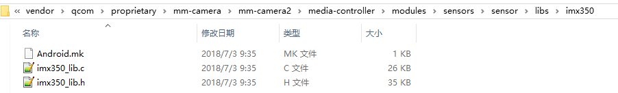
注意Android.mk中
LOCAL_SRC_FILES:= imx350_lib.c
LOCAL_MODULE := libmmcamera_imx350
需要在 @\vendor\qcom\proprietary\common\config\device-vendor.mk中导入模块,添加修改如下:
MM_CAMERA += libmmcamera_imx350
2. 导入Camera Chromatix 默认效果参数
将默认的 Chromatix 效果参数放入如下目录
@\vendor\qcom\proprietary\mm-camera\mm-camera2\media-controller\modules\sensors\chromatix\0310\chromatix_imx350_sunny
其中包括了,3A 及 ISP 的效果参数,后续Camera Turnning 工程师会代码效果后修以下面的参数。
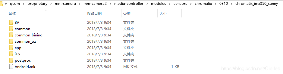
由于上面每个分别会编译成多个库,所以我们要注意每个库的名字,我们进入每个文件夹的Android.mk 看下:
@ mm-camera2\media-controller\modules\sensors\chromatix\0310\chromatix_imx350_sunny\3A
LOCAL_MODULE           :=  libchromatix_imx350_sunny_default_preview_3a
LOCAL_MODULE           :=  libchromatix_imx350_sunny_default_video_3a
LOCAL_MODULE           :=  libchromatix_imx350_sunny_hfr_120_3a
LOCAL_MODULE           :=  libchromatix_imx350_sunny_hfr_60_3a
LOCAL_MODULE           :=  libchromatix_imx350_sunny_hfr_90_3a
LOCAL_MODULE           :=  libchromatix_imx350_sunny_zsl_preview_3a
LOCAL_MODULE           :=  libchromatix_imx350_sunny_zsl_video_3a

@ mm-camera2\media-controller\modules\sensors\chromatix\0310\chromatix_imx350_sunny\common
LOCAL_MODULE           :=  libchromatix_imx350_sunny_common

@ mm-camera2\media-controller\modules\sensors\chromatix\0310\chromatix_imx350_sunny\cpp
LOCAL_MODULE           := libchromatix_imx350_sunny_cpp_hfr_120
LOCAL_MODULE           := libchromatix_imx350_sunny_cpp_hfr_60
LOCAL_MODULE           := libchromatix_imx350_sunny_cpp_hfr_90
LOCAL_MODULE           := libchromatix_imx350_sunny_cpp_liveshot
LOCAL_MODULE           := libchromatix_imx350_sunny_cpp_preview
LOCAL_MODULE           := libchromatix_imx350_sunny_cpp_snapshot
LOCAL_MODULE           := libchromatix_imx350_sunny_cpp_video

@ mm-camera2\media-controller\modules\sensors\chromatix\0310\chromatix_imx350_sunny\isp
LOCAL_MODULE           := libchromatix_imx350_sunny_hfr_120
LOCAL_MODULE           := libchromatix_imx350_sunny_hfr_60
LOCAL_MODULE           := libchromatix_imx350_sunny_hfr_90
LOCAL_MODULE           := libchromatix_imx350_sunny_liveshot
LOCAL_MODULE           := libchromatix_imx350_sunny_preview
LOCAL_MODULE           := libchromatix_imx350_sunny_snapshot
LOCAL_MODULE           := libchromatix_imx350_sunny_default_video
LOCAL_MODULE           := libchromatix_imx350_sunny_postproc
LOCAL_MODULE           := libchromatix_imx350_sunny_oz_preview_3a
LOCAL_MODULE           := libchromatix_imx350_sunny_oz_video_3a

@ mm-camera2\media-controller\modules\sensors\chromatix\0310\chromatix_imx350_sunny\postproc
LOCAL_MODULE           := libchromatix_imx350_sunny_postproc
在 @\vendor\qcom\proprietary\common\config\device-vendor.mk中添加如下修改:
MM_CAMERA += libchromatix_imx350_sunny_default_preview_3a
MM_CAMERA += libchromatix_imx350_sunny_default_video_3a
MM_CAMERA += libchromatix_imx350_sunny_hfr_120_3a
MM_CAMERA += libchromatix_imx350_sunny_hfr_60_3a
MM_CAMERA += libchromatix_imx350_sunny_hfr_90_3a
MM_CAMERA += libchromatix_imx350_sunny_zsl_preview_3a
MM_CAMERA += libchromatix_imx350_sunny_zsl_video_3a

MM_CAMERA += libchromatix_imx350_sunny_common

MM_CAMERA += libchromatix_imx350_sunny_cpp_hfr_120
MM_CAMERA += libchromatix_imx350_sunny_cpp_hfr_60
MM_CAMERA += libchromatix_imx350_sunny_cpp_hfr_90
MM_CAMERA += libchromatix_imx350_sunny_cpp_liveshot
MM_CAMERA += libchromatix_imx350_sunny_cpp_preview
MM_CAMERA += libchromatix_imx350_sunny_cpp_snapshot
MM_CAMERA += libchromatix_imx350_sunny_cpp_video

MM_CAMERA += libchromatix_imx350_sunny_hfr_120
MM_CAMERA += libchromatix_imx350_sunny_hfr_60
MM_CAMERA += libchromatix_imx350_sunny_hfr_90
MM_CAMERA += libchromatix_imx350_sunny_liveshot
MM_CAMERA += libchromatix_imx350_sunny_preview
MM_CAMERA += libchromatix_imx350_sunny_snapshot
MM_CAMERA += libchromatix_imx350_sunny_default_video
MM_CAMERA += libchromatix_imx350_sunny_postproc
MM_CAMERA += libchromatix_imx350_sunny_oz_preview_3a
MM_CAMERA += libchromatix_imx350_sunny_oz_video_3a

MM_CAMERA += libchromatix_imx350_sunny_postproc
2.1 chromatix version 0309 和 0310 定义
具体走哪个是由 CHROMATIX_VERSION来控制的,其定义于:@\vendor\qcom\proprietary\mm-camera\Android.mk
ifeq ($(BUILD_SERVER), true)
  CHROMATIX_VERSION := 0208
else ifeq ($(BUILD_MM_CAMERA2), true)
  ifeq ($(OEM_CHROMATIX_0308), 1)
    CHROMATIX_VERSION := 0308E
  else ifeq ($(call is-board-platform-in-list,sdm660 msm8998),true)
    CHROMATIX_VERSION := 0310
  else
    CHROMATIX_VERSION := 0309
  endif
endif

ifeq ($(OEM_CHROMATIX_0310), 1)
  OEM_CHROMATIX:=true
endif

ifeq ($(OEM_CHROMATIX), true)
  LOCAL_CHROMATIX_PATH := $(LOCAL_PATH)/../mm-camera-ext/mm-camerasdk/sensor/includes/$(CHROMATIX_VERSION)
  LOCAL_EXTEN_ISP_INCLUDES := $(LOCAL_PATH)/../mm-camera-ext/mm-camera2/media-controller/modules/isp2/
  LOCAL_EXTEN_PPROC_INCLUDES := $(LOCAL_PATH)/../mm-camera-ext/mm-camera2/media-controller/modules/pproc-new/cpp/
  LOCAL_EXTEN_CHROMATIX_FILE_PATH := $(LOCAL_PATH)/../mm-camera-ext/mm-camera2/media-controller/modules/sensors/chromatix/$(CHROMATIX_VERSION)
else
  LOCAL_CHROMATIX_PATH := $(LOCAL_PATH)/../mm-camerasdk/sensor/includes/$(CHROMATIX_VERSION)
  LOCAL_EXTEN_CHROMATIX_FILE_PATH := $(LOCAL_PATH)/mm-camera2/media-controller/modules/sensors/chromatix/$(CHROMATIX_VERSION)
endif
3. 修改 Sensor Config XML
@ qcom\proprietary\mm-camera\mm-camera2\media-controller\modules\sensors\config\Android.mk
@ qcom\proprietary\mm-camera\mm-camera2\media-controller\modules\sensors\config\imx350_suny.xml
@ qcom\proprietary\mm-camera\mm-camera2\media-controller\modules\sensors\config\sdm660_camera.xml
3.1 imx350_sunny.xml
@\mm-camera2\media-controller\modules\sensors\configs\imx350_sunny.xml
在该文件中,主要是描述了对应的 chromatix 模块名字,如下:
可以看出,和前面 chromatix 中的模块名字一模一样。
<!--
CommonChromatixInfo:
    CommonChromatixInfo is the information about chromatix needed for various use cases.
    Ex:- Preview, Snapshot, ZSL, HFR, HDR, Video, Liveshot for ISP, CPP,3A and SW PostProc.
    Entries in this node are common for all sensor modes.

ResolutionChromatixInfo:
    ResolutionChromatixInfo is the information about chromatix needed for various use cases.
    Ex:- Preview, Snapshot, ZSL, HFR, HDR, Video, Liveshot for ISP, CPP, 3A and SW PostProc.
    Entries in this node are specific to sensor resolution.

ChromatixName:
    Contains the list of chromatix names for all modules.
    special_mode_mask:
        It is the bit mask for special modes, which is used for  chromatix selection.
        Special modes can be any mode that needs a special chromatix.
        Ex:- scene mode, DZOOM mode, OIS capture mode, flash mode
        This is applicable for CommonChromatixInfo and ResolutionChromatixInfo.
        special_mode_mask="0" means none of the special modes are selected.
    sensor_resolution_index:
        It is the sensor resolution index for which chromatix libraries will be choosen.
        It is applicable only in ResolutionChromatixInfo.

ISPCommon : 	Common tuning library name for ISP
ISPPreview : 	Preview tuning library name for ISP
ISPSnapshot : 	Snapshot tuning library name for ISP
CPPCommon : 	Common tuning library name for CPP
CPPPreview : 	Preview tuning library name for CPP
CPPSnapshot : 	Snapshot tuning library name for CPP
CPPLiveshot : 	Liveshot tuning library name for CPP
PostProc :		Tuning library name for postproc module
A3Preview :		Preview tuning library for 3A
A3Video :		Video tuning library for 3A

Order of Resolution Pick:
    Assume the current sensor mode is "r" and special mode mask is "s".
    Chromatix for a module and type is choosen in this order till we find a valid chroamtix file name or else NULL is returned.
    1) From ResolutionChromatixInfo node for which sensor_resolution_index is "r" and special_mode_mask is "s".
    2) From CommonChromatixInfo node for which special_mode_mask is "s".
    3) From ResolutionChromatixInfo node for which sensor_resolution_index is "r" and special_mode_mask is "0".
    4) From CommonChromatixInfo node for which special_mode_mask is "0".
    5) NULL is returned if we dont find in any of the above cases.

special_mode_mask values:
    SENSOR_SPECIAL_MODE_NONE = 0,
    SENSOR_SPECIAL_MODE_FLASH = 1,
    SENSOR_SPECIAL_MODE_ZOOM_UPSCALE = 2,
    SENSOR_SPECIAL_MODE_ZOOM_DOWNSCALE = 4,
    SENSOR_SPECIAL_MODE_OIS_CAPTURE = 8,
-->

<ChromatixConfigurationRoot>
  <CommonChromatixInfo>
    <ChromatixName>
      <PostProc>imx350_sunny_postproc</PostProc>
    </ChromatixName>
  </CommonChromatixInfo>
  <ResolutionChromatixInfo>
    <ChromatixName sensor_resolution_index="0">
      <ISPCommon>imx350_sunny_common</ISPCommon>
      <ISPPreview>imx350_sunny_snapshot</ISPPreview>
      <ISPSnapshot>imx350_sunny_snapshot</ISPSnapshot>
      <ISPVideo>imx350_sunny_default_video</ISPVideo>
      <CPPPreview>imx350_sunny_cpp_preview</CPPPreview>
      <CPPSnapshot>imx350_sunny_cpp_snapshot</CPPSnapshot>
      <CPPVideo>imx350_sunny_cpp_video</CPPVideo>
      <CPPLiveshot>imx350_sunny_cpp_liveshot</CPPLiveshot>
      <A3Preview>imx350_sunny_zsl_preview_3a</A3Preview>
      <A3Video>imx350_sunny_zsl_video_3a</A3Video>
    </ChromatixName>
    <ChromatixName sensor_resolution_index="1">
      <ISPCommon>imx350_sunny_common_oz</ISPCommon>
      <ISPPreview>imx350_sunny_oz_preview</ISPPreview>
      <ISPSnapshot>imx350_sunny_oz_snapshot</ISPSnapshot>
      <ISPVideo>imx350_sunny_oz_preview</ISPVideo>
      <CPPPreview>imx350_sunny_cpp_oz_preview</CPPPreview>
      <CPPSnapshot>imx350_sunny_cpp_oz_snapshot</CPPSnapshot>
      <CPPVideo>imx350_sunny_cpp_oz_preview</CPPVideo>
      <CPPLiveshot>imx350_sunny_cpp_liveshot</CPPLiveshot>
      <A3Preview>imx350_sunny_oz_preview_3a</A3Preview>
      <A3Video>imx350_sunny_oz_preview_3a</A3Video>
    </ChromatixName>
    <ChromatixName sensor_resolution_index="2">
      <ISPCommon>imx350_sunny_common_bining</ISPCommon>
      <ISPPreview>imx350_sunny_preview</ISPPreview>
      <ISPSnapshot>imx350_sunny_snapshot</ISPSnapshot>
      <ISPVideo>imx350_sunny_default_video</ISPVideo>
      <CPPPreview>imx350_sunny_cpp_preview</CPPPreview>
      <CPPSnapshot>imx350_sunny_cpp_snapshot</CPPSnapshot>
      <CPPVideo>imx350_sunny_cpp_video</CPPVideo>
      <CPPLiveshot>imx350_sunny_cpp_liveshot</CPPLiveshot>
      <A3Preview>imx350_sunny_default_preview_3a</A3Preview>
      <A3Video>imx350_sunny_default_video_3a</A3Video>
    </ChromatixName>
    <ChromatixName sensor_resolution_index="2" special_mode_mask="SCENE_BOKEH_MODE|">
      <ISPCommon>imx350_sunny_common_bining</ISPCommon>
      <ISPPreview>imx350_sunny_preview_bokeh</ISPPreview>
      <ISPSnapshot>imx350_sunny_preview_bokeh</ISPSnapshot>
      <ISPVideo>imx350_sunny_default_video</ISPVideo>
      <CPPPreview>imx350_sunny_cpp_preview</CPPPreview>
      <CPPSnapshot>imx350_sunny_cpp_snapshot</CPPSnapshot>
      <CPPVideo>imx350_sunny_cpp_video</CPPVideo>
      <CPPLiveshot>imx350_sunny_cpp_liveshot</CPPLiveshot>
      <A3Preview>imx350_sunny_default_preview_3a</A3Preview>
      <A3Video>imx350_sunny_default_video_3a</A3Video>
    </ChromatixName>
    <ChromatixName sensor_resolution_index="3">
      <ISPCommon>imx350_sunny_common</ISPCommon>
      <ISPPreview>imx350_sunny_hfr_90</ISPPreview>
      <ISPSnapshot>imx350_sunny_hfr_90</ISPSnapshot>
      <ISPVideo>imx350_sunny_hfr_90</ISPVideo>
      <CPPPreview>imx350_sunny_cpp_hfr_90</CPPPreview>
      <CPPSnapshot>imx350_sunny_cpp_hfr_90</CPPSnapshot>
      <CPPVideo>imx350_sunny_cpp_hfr_90</CPPVideo>
      <CPPLiveshot>imx350_sunny_cpp_liveshot</CPPLiveshot>
      <A3Preview>imx350_sunny_hfr_90_3a</A3Preview>
      <A3Video>imx350_sunny_hfr_90_3a</A3Video>
    </ChromatixName>
    <ChromatixName sensor_resolution_index="4">
      <ISPCommon>imx350_sunny_common</ISPCommon>
      <ISPPreview>imx350_sunny_hfr_120</ISPPreview>
      <ISPSnapshot>imx350_sunny_hfr_120</ISPSnapshot>
      <ISPVideo>imx350_sunny_hfr_120</ISPVideo>
      <CPPPreview>imx350_sunny_cpp_hfr_120</CPPPreview>
      <CPPSnapshot>imx350_sunny_cpp_hfr_120</CPPSnapshot>
      <CPPVideo>imx350_sunny_cpp_hfr_120</CPPVideo>
      <CPPLiveshot>imx350_sunny_cpp_liveshot</CPPLiveshot>
      <A3Preview>imx350_sunny_hfr_120_3a</A3Preview>
      <A3Video>imx350_sunny_hfr_120_3a</A3Video>
    </ChromatixName>
  </ResolutionChromatixInfo>
</ChromatixConfigurationRoot>
3.2 sdm660_camera.xml
<!--
CameraModuleConfig :
    This node must be added for each module prosent in the device.
    It contain all information about the module present.
    The number of nodes of CameraModuleConfig indicate number of modules
    to be probed on the device.
    Maximum number of CameraModuleConfig nodes is 10
- - - - - - - - - - - - - - - - - - - - - - - - - - - - - - - - - - - - - - - -

*CameraId : Camera Id is the Slot number in which the mode is plugged. Valid values are 0, 1, 2 and 3.
*SensorName : Name of the sensor present on the module. The sensor library name should be of the form libmmcamera_<SensorName>.so
ActuatorName : Name of the actuator on this module.The actuator library name should be of the form libactuator_<ActuatorName>.so.
    			If there is no actuator remove the <ActuatorName> node.
EepromName : Name of the eeprom on this module.
    Eeprom lib name should be of the form libmmcamera_<EepromName>_eeprom.so If there is no eeprom remove the <EepromName> node.
FlashName :
    Name of the flash on this module.
    The flash library name should be of the form libflash_<FlashName>.so. If there is no flash remove the <FlashName> node.
ChromatixName :
    Name of the tuning xml file.
    Tuning file contains the list of chromatix library names. If there is no tuning xml file remove the <ChromatixName> node.
Position :
    Position of the sensor module. Valid values are: BACK, FRONT and BACK_AUX
MountAngle :
    Angle at which the sensor is mounted. Valid values are 0, 90, 180, 270 and 360.
    To use default mountangle mentioned in kernel use 360.

CsiInfo : This node contains information about the receiver configuration.
- - - - - - - - - - - - - - - - - - - - - - - - - - - - - - - - - - - - - - - -

*CSIDCore : CSID core to receive the data. Valid values are 0, 1, 2 and 3.
*LaneMask : Mask to mention which lane is enabled.
    LaneMask[0] for DL0.
    LaneMask[1] for CLK.
    LaneMask[2] for DL1.
    LaneMask[3] for DL2.
    LaneMask[4] for DL3
*LaneAssign : Number which describes the lane mapping between sensor and PHY.
    LaneAssign[0:3] is sensor lane number connected to data lane 0 of PHY on MSM
    LaneAssign[4:7] is sensor lane number connected to data lane 2 of PHY on MSM
    LaneAssign[8:11] is sensor lane number connected to data lane 3 of PHY on MSM
    LaneAssign[12:15] is sensor lane number connected to data lane 4 of PHY on MSM

    NOTE : Lane 1 is reserved for the clock lane.
        Wiring and setting it to a data lane is prohibited.
ComboMode :
    Flag to enable combo mode.
    This flag is enabled if multiple sensors are using same CSI-PHY receiver

LensInfo : Information of the lens present in the module.
- - - - - - - - - - - - - - - - - - - - - - - - - - - - - - - - - - - - - - - -

*FocalLength : FocalLength of the lens in micometers. Distance between the center of curvature to the focal point.
*FNumber : FNumber of the lens.
*TotalFocusDistance : The total distance in meters the lens could focus.
*HorizontalViewAngle : HorizontalViewAngle in degrees
*VerticalViewAngle : VerticalViewAngle in degrees
*MinFocusDistance : Minimum distance in meters the lens could focus.

*VARIABLES MARKED WITH ASTRICK (*) ARE MANDATORY.
-->
<CameraConfigurationRoot>
  <CameraModuleConfig>
	    <CameraId>0</CameraId>							// camera id =0,注意和 dts 中 cell-index 一致
	    <SensorName>imx362</SensorName>					// sensor name , 这个名字用来找到对应的 sensor lib 库,所以不能错了
	    <ActuatorName>ak7374</ActuatorName>				// lens name ,用来找到对应的马达驱动
	    <EepromName>sony_imx362</EepromName>			// eeprom name, 用来找到对应的eeprom驱动
	    <ChromatixName>imx362_chromatix</ChromatixName>	// chromatix name,用来找到对应的效果文件
	    <FlashName>pmic</FlashName>						// flashlight name, 用来找到 mm-camera2\media-controller\modules\sensors\flash\libs 下面对应的库
	    <ModesSupported>1</ModesSupported>
	    <Position>BACK</Position>						// 后摄
	    <MountAngle>90</MountAngle>						// 旋转90度,注意和 dts 中配置的一样
	    <CSIInfo>
		      <CSIDCore>0</CSIDCore>					// CS 0
		      <LaneMask>0x1F</LaneMask>					// 4 lane 和 1 clk 同时使能
		      <LaneAssign>0x4320</LaneAssign>
		      <ComboMode>0</ComboMode>
	    </CSIInfo>
	    <LensInfo>										// 马达相关的参数,具体看模组 sepc
		      <FocalLength>3.94</FocalLength>
		      <FNumber>1.9</FNumber>
		      <TotalFocusDistance>4.64</TotalFocusDistance>
		      <HorizontalViewAngle>70.4</HorizontalViewAngle>
		      <VerticalViewAngle>55.7</VerticalViewAngle>
		      <MinFocusDistance>0.1</MinFocusDistance>
	    </LensInfo>
  </CameraModuleConfig>
	    <CameraModuleConfig>
	    <CameraId>1</CameraId>							// camera id =1
	    <SensorName>imx350</SensorName>
	    <ActuatorName>dw9800</ActuatorName>
	    <EepromName>sony_imx350</EepromName>
	    <ChromatixName>imx350_chromatix</ChromatixName>
	    <ModesSupported>1</ModesSupported>
	    <Position>BACK_AUX</Position>					// 后二摄
	    <MountAngle>90</MountAngle>
	    <CSIInfo>
		      <CSIDCore>1</CSIDCore>					// CS 1
		      <LaneMask>0x1F</LaneMask>
		      <LaneAssign>0x4320</LaneAssign>
		      <ComboMode>0</ComboMode>
	    </CSIInfo>
	    <LensInfo>
		      <FocalLength>5.3</FocalLength>
		      <FNumber>2.6</FNumber>
		      <TotalFocusDistance>5.0</TotalFocusDistance>
		      <HorizontalViewAngle>51.4</HorizontalViewAngle>
		      <VerticalViewAngle>40.0</VerticalViewAngle>
		      <MinFocusDistance>0.3</MinFocusDistance>
	    </LensInfo>
  </CameraModuleConfig>
  <CameraModuleConfig>
	    <CameraId>2</CameraId>							// camera id =2
	    <SensorName>s5k4h7yx</SensorName>
	    <EepromName>holitech_s5k4h7yx</EepromName>
	    <ChromatixName>s5k4h7yx_chromatix</ChromatixName>
	    <ModesSupported>1</ModesSupported>
	    <Position>FRONT</Position>						// 前摄
	    <MountAngle>270</MountAngle>					// 旋转270度
	    <CSIInfo>
		      <CSIDCore>2</CSIDCore>					// CS2
		      <LaneMask>0x1F</LaneMask>
		      <LaneAssign>0x4320</LaneAssign>
		      <ComboMode>0</ComboMode>
	    </CSIInfo>
	    <LensInfo>										// 马达相关参数
		      <FocalLength>2.47</FocalLength>
		      <FNumber>2.0</FNumber>
		      <TotalFocusDistance>1.9</TotalFocusDistance>
		      <HorizontalViewAngle>63.84</HorizontalViewAngle>
		      <VerticalViewAngle>47.88</VerticalViewAngle>
		      <MinFocusDistance>0.1</MinFocusDistance>
	    </LensInfo>
  </CameraModuleConfig>
</CameraConfigurationRoot>
3.3 sensors_configs_Android.mk
@\vendor\qcom\proprietary\mm-camera\mm-camera2\media-controller\modules\sensors\configs\Android.mk
在 Android.mk 中,添加 xml 编译。
ifeq ($(call is-board-platform-in-list, sdm660),true)
include $(CLEAR_VARS)
LOCAL_MODULE:= camera_config.xml
LOCAL_MODULE_CLASS := EXECUTABLES
LOCAL_SRC_FILES := sdm660_camera.xml
LOCAL_MODULE_TAGS := optional
LOCAL_MODULE_PATH := $(TARGET_OUT)/etc/camera
LOCAL_MODULE_OWNER := qti
include $(BUILD_PREBUILT)

include $(CLEAR_VARS)
LOCAL_MODULE:= imx350_sunny.xml
LOCAL_MODULE_CLASS := EXECUTABLES
LOCAL_SRC_FILES := imx350_sunny.xml
LOCAL_MODULE_TAGS := optional
LOCAL_MODULE_PATH := $(TARGET_OUT)/etc/camera
LOCAL_MODULE_OWNER := qti
include $(BUILD_PREBUILT)
4. 导入 Camera AF 马达lib库代码
在前面sdm660_camera.xml中,我们可以看出,
使用了 <ActuatorName>ak7374</ActuatorName>和<ActuatorName>dw9800</ActuatorName>这两种马达。
马达lib库代码位于@vendor\qcom\proprietary\mm-camera\mm-camera2\media-controller\modules\sensors\actuator\libs中。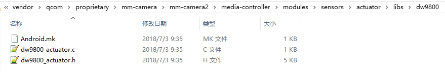
从 Android.mk中可以看出,各模块名字为:
LOCAL_MODULE := libactuator_dw9800
LOCAL_MODULE := libactuator_ak7374
导入代码后,在 @\vendor\qcom\proprietary\common\config\device-vendor.mk
中添加如下代码,将模块导入进来:
MM_CAMERA += libactuator_dw9800
MM_CAMERA += libactuator_ak7374
5. 导入 Camera Flashlight 闪光灯lib库代码
在前面sdm660_camera.xml中,可以看出flashlight 使用的是默认的 <FlashName>pmic</FlashName>驱动。
代码位置在 @\vendor\qcom\proprietary\mm-camera\mm-camera2\media-controller\modules\sensors\flash\libs\pmic
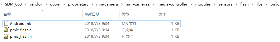
在Android.mk中,模块名字为:
LOCAL_MODULE := libflash_pmic
导入代码后,在 @\vendor\qcom\proprietary\common\config\device-vendor.mk中添加如下代码,将模块导入进来:
MM_CAMERA += libflash_pmic
6. 导入 Camera Eeprom OTP lib库代码
在前面sdm660_camera.xml中,可以看出Eeprom使用的是默认的 <EepromName>sony_imx362</EepromName>和<EepromName>sony_imx350</EepromName>驱动。
代码位置在 @\vendor\qcom\proprietary\mm-camera\mm-camera2\media-controller\modules\sensors\eeprom\libs\sony_imx350
在Android.mk中,模块名字为:
LOCAL_MODULE := libmmcamera_sony_imx350_eeprom
导入代码后,在 @\vendor\qcom\proprietary\common\config\device-vendor.mk中添加如下代码,将模块导入进来:
MM_CAMERA += libmmcamera_sony_imx350_eeprom
好,至此,camera 代码移植相关的工作就完了,如果这些相关的文件都配置正确的话,
接下来您就可以,编译下载看下是否正常点亮,及抓log 调试下。


 468
468


 被折叠的 条评论
为什么被折叠?
被折叠的 条评论
为什么被折叠?
 到【灌水乐园】发言


