


是老师布置的作业,拖到ddl才开始,opencv也才刚接触,有自己结合百度的一点理解,如有误,请谅解!
DCT图像压缩
先贴一段在matlab上实现的代码,这个在网上都可以查到,就不赘述了
I=imread('cameraman.tif');
I=im2double(I);%将图像转换为双精度
T=dctmtx(8);% 返回8*8的DCT变换矩阵
B=blkproc(I,[8 8],'P1*x*P2',T,T');
% x就是每一个分成的8*8大小的块,P1*x*P2相当于像素块的处理函数,p1=T p2=T’,
%也就是fun=p1*x*p2'=T*x*T'的功能是进行离散余弦变换
mask=   [1 1 1 1 0 0 0 0
         1 1 1 0 0 0 0 0
         1 1 0 0 0 0 0 0
         1 0 0 0 0 0 0 0
         0 0 0 0 0 0 0 0
         0 0 0 0 0 0 0 0
         0 0 0 0 0 0 0 0
         0 0 0 0 0 0 0 0];% 保留左上角十个系数
B2=blkproc(B,[8 8],'P1.*x',mask);%舍弃每个块中的高频系数,达到图像压缩的目的
I2=blkproc(B2,[8 8],'P1*x*P2',T',T); %进行反余弦变换,得到压缩后的图象
figure(1);
subplot(1,4,1),imshow(I);
subplot(1,4,2),imshow(B);
subplot(1,4,3),imshow(B2);
subplot(1,4,4),imshow(I2);
Z  = imabsdiff(I,I2);
figure(2);
imshow(Z);
思路如下:
先划分处理块大小,对每个块分别进行DCT变换,再舍弃每个块中的高频系数,再进行反余弦变换,得到压缩图像(即先使用DCT函数将低频的点都集中在左上角,再对右下角的高频数据丢弃)
老师要求我们用c++ + opencv实现。配置环境真的是。。。。
试过用clion和vscode配,失败了,还是老老实实用vs2019吧。
附 大佬配置的视频,十分感谢!
https://www.bilibili.com/video/BV1mE411P76Mp=1&vd_source=393e209b3fa00543c23db5753b265d30
下面是用c++ 实现的代码
RGB图(下面有灰度图,其实差不多)
#include <opencv2/opencv.hpp>
#include <iostream>
using namespace cv;
using namespace std;
double T = 100;
int main()
{
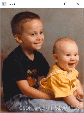
Mat src = imread("D:\\Matlab\\toolbox\\images\\imdata\\kids.tif");//先读入图像,在这里读入的是RGB图像,有三个通道
imshow("clock", src);//先显示图像
int big;
big = 8;//定义一下掩盖矩阵的大小
vector<Mat> mv;
split(src, mv);//通道分割
Mat b = Mat_<float>(mv[0]);
Mat g = Mat_<float>(mv[1]);
Mat r = Mat_<float>(mv[2]);
b.convertTo(b, CV_32F, 1.0 / 255);
g.convertTo(g, CV_32F, 1.0 / 255);
r.convertTo(r, CV_32F, 1.0 / 255);
//要进行DCT变换先转换成float,我也不知道为什么
Mat bDCT = Mat_<float>(b); //这里先复制矩阵,后面有用
Mat gDCT = Mat_<float>(g);
Mat rDCT = Mat_<float>(r);
int w = b.rows;
int h = b.cols;//三个通道的大小都是一样的,所以只要取一个就好了
//DCT变换每个通道都做一遍
for (int i1 = 0; i1 < (h / big); i1++) {//注意这里的取值和我们平常遇到的x,y不一样 一张宽度x像素、高度y像素的灰度图保存在一个y * x的矩阵中。
for (int j1 = 0; j1 < (w / big); j1++) {
dct(b(Rect(i1 * big, j1 * big, big, big)), bDCT(Rect(i1 * big, j1 * big, big, big)));//Rect是滑块函数,从指定位置取指定大小的矩阵,这就是跟Matlab分块处理一样
}
}
//发现有的图像不是长宽相同的,所以取整除,而没有取到数据,跟之前相同就行了,复制的用处就来啦
for (int i1 = 0; i1 < (h / big); i1++) {
for (int j1 = 0; j1 < (w / big); j1++) {
dct(g(Rect(i1 * big, j1 * big, big, big)), gDCT(Rect(i1 * big, j1 * big, big, big)));
}
}
for (int i1 = 0; i1 < (h / big); i1++) {
for (int j1 = 0; j1 < (w / big); j1++) {
dct(r(Rect(i1 * big, j1 * big, big, big)), rDCT(Rect(i1 * big, j1 * big, big, big)));
}
}
int mask[8][8] = {//定义掩盖矩阵
{1, 1, 1, 1, 0, 0, 0, 0},
{1, 1, 1, 0, 0, 0, 0, 0},
{1, 1, 0, 0, 0, 0, 0, 0},
{1, 0, 0, 0, 0, 0, 0, 0},
{0, 0, 0, 0, 0, 0, 0, 0},
{0, 0, 0, 0, 0, 0, 0, 0},
{0, 0, 0, 0, 0, 0, 0, 0},
{0, 0, 0, 0, 0, 0, 0, 0},
};
//根据mask 矩阵 去掉右下角的数据,同样对每个通道做一次
for (int i1 = 0; i1 < (bDCT.rows / big); i1++)
{
for (int j1 = 0; j1 < (bDCT.cols / big); j1++)
{
for (int i = 0; i < big; i++)
{
for (int j = 0; j < big; j++)
{
if (mask[i % big][j % big] == 0)
{
bDCT.at<int>(i1 * big + i, j1 * big + j) = 0;//这里和mask矩阵相乘是同一个意思,同时扫描mask和DCT变换后的矩阵,当mask矩阵扫描到的值为0时,把DCT矩阵也置零,去掉高频数据
}
}
}
}
}
for (int i1 = 0; i1 < (gDCT.rows / big); i1++)
{
for (int j1 = 0; j1 < (gDCT.cols / big); j1++)
{
for (int i = 0; i < big; i++)
{
for (int j = 0; j < big; j++)
{
if (mask[i % big][j % big] == 0)
{
gDCT.at<int>(i1 * big + i, j1 * big + j) = 0;;
}
}
}
}
} for (int i1 = 0; i1 < (rDCT.rows / big); i1++)
{
for (int j1 = 0; j1 < (rDCT.cols / big); j1++)
{
for (int i = 0; i < big; i++)
{
for (int j = 0; j < big; j++)
{
if (mask[i % big][j % big] == 0)
{
rDCT.at<int>(i1 * big + i, j1 * big + j) = 0;;
}
}
}
}
}
Mat iDctb = bDCT;
Mat iDctg = gDCT;
Mat iDctr = rDCT;
//进行逆DCT变换,同做三次
for (int i1 = 0; i1 < (h / big); i1++) {
for (int j1 = 0; j1 < (w / big); j1++) {
idct(bDCT(Rect(i1 * big, j1 * big, big, big)), iDctb(Rect(i1 * big, j1 * big, big, big)));
}
}
for (int i1 = 0; i1 < (h / big); i1++) {
for (int j1 = 0; j1 < (w / big); j1++) {
idct(gDCT(Rect(i1 * big, j1 * big, big, big)), iDctg(Rect(i1 * big, j1 * big, big, big)));
}
}
for (int i1 = 0; i1 < (h / big); i1++) {
for (int j1 = 0; j1 < (w / big); j1++) {
idct(rDCT(Rect(i1 * big, j1 * big, big, big)), iDctr(Rect(i1 * big, j1 * big, big, big)));
}
}
mv[0] = iDctb;
mv[1] = iDctg;
mv[2] = iDctr;
Mat dst;
merge(mv, dst);//通道合并
imshow("DstImage",dst);//显示图像
waitKey(0);
return 0;
}
效果如下:
原图:
压缩后:
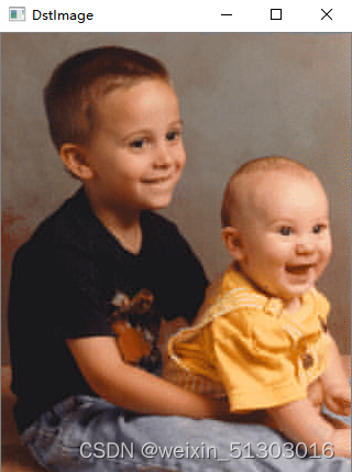
如果感觉不明显,可以减少mask矩阵1的个数。
灰度图
int main()
{
    Mat src = imread("D:\\Matlab\\toolbox\\images\\imdata\\coins.png",0);
    imshow("clock", src);
    src = Mat_<float>(src);
    int w = src.rows;
    int h = src.cols;


    int big;
    big = 8;
    src.convertTo(src, CV_32F, 1.0 / 255);
    Mat srcDCT = Mat_<float>(src);


    for (int i1 = 0; i1 < (h / big); i1++) {
        for (int j1 = 0; j1 < (w / big); j1++) {
            dct(src(Rect(i1 * big, j1 * big, big, big)),srcDCT(Rect(i1 * big, j1 * big, big, big)));

        }
    }


    int mask[8][8] = {
        {1, 1, 1, 1, 0, 0, 0, 0},
        {1, 1, 1, 0, 0, 0, 0, 0},
        {1, 1, 0, 0, 0, 0, 0, 0},
        {1, 0, 0, 0, 0, 0, 0, 0},
        {0, 0, 0, 0, 0, 0, 0, 0},
        {0, 0, 0, 0, 0, 0, 0, 0},
        {0, 0, 0, 0, 0, 0, 0, 0},
        {0, 0, 0, 0, 0, 0, 0, 0},

    };
    double s;
    for (int i1 = 0; i1 < (srcDCT.rows / big); i1++) {
        for (int j1 = 0; j1 < (srcDCT.cols / big); j1++) {

            for (int i = 0; i < big; i++)
            {

                for (int j = 0; j < big; j++)
                {
                    if (mask[i % big][j % big] == 0) {
                        srcDCT.at<int>(i1 * big + i, j1 * big + j) = 0;;


                    }
                    else {
                        s = 0;
                    }
                }
            }
        }
    }
   Mat iDct1 = srcDCT;

    for (int i1 = 0; i1 < (h / big); i1++) {
        for (int j1 = 0; j1 < (w / big); j1++) {
            idct(srcDCT(Rect(i1 * big, j1 * big, big, big)), iDct1(Rect(i1 * big, j1 * big, big, big)));

        }
    }

    imshow("c", srcDCT);


    imshow("DstImage",iDct1);

    waitKey(0);

    return 0;

}
感谢观看,如有误,请不吝赐教。


 2835
2835


 被折叠的 条评论
为什么被折叠?
被折叠的 条评论
为什么被折叠?
 到【灌水乐园】发言


