


教学资料来自【STM32入门教程-2023版 细致讲解 中文字幕】 https://www.bilibili.com/video/BV1th411z7sn/?p=5&share_source=copy_web&vd_source=c6cfedd1c739ca8502f041514e158616
在keil中,每个代码最后一行必须是空的,不然运行会报错
配置库函数

文件图标前面带个钥匙的就是只读文件,不可以更改,我们只需要更改user里面的文件
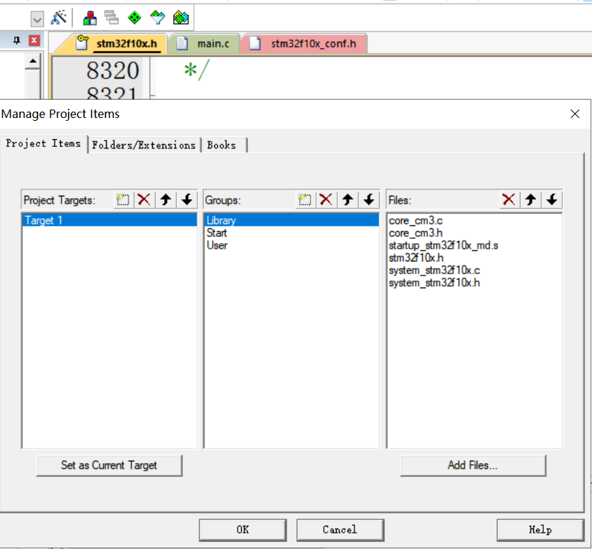
点一下三个箱子的按钮,把不用更改的放到最上面方便查看
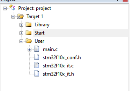
效果如下:
用库函数实现点灯
1.开启时钟
时钟:单片机的心脏,所有的外设的运作都需要时钟供能。
时钟周期:又称为振荡周期,可以简单理解为传输一个0或1所需要的时间
指令周期:执行一条指令(如 MOV A, #34H)所需要的时间。对于不同类型的指令,指令周期长度可能不同。
机器周期:执行一个动作的时间周期。如:执行一个指令需要”取指令并译码“、”执行操作数“两个动作。
原文链接:https://blog.csdn.net/qq_43460068/article/details/122203020
简单的说,时钟是单片机的脉搏,是单片机的驱动源,使用任何一个外设都必须打开相应的时钟。这样的好处是,如果不使用一个外设的时候,就把它的时钟关掉,从而可以降低系统的功耗,达到节能,实现低功耗的效果。每个时钟tick,系统都会处理一步数据,这样才能让工作不出现紊乱。
首先,任何外设都需要时钟,51单片机,stm32,430等等,因为寄存器是由D触发器组成的,往触发器里面写东西,前提条件是有时钟输入。
51单片机不需要配置时钟,是因为一个时钟开了之后所有的功能都可以用了,而这个时钟是默认开启的,比如有一个水库,水库有很多个门,这些门默认是开启的,所以每个门都会出水,我们需要哪个门的水的时候可以直接用,但是也存在一个问题,其他没用到的门也在出水,即也在耗能。这里水库可以认为是能源,门可以认为是每个外设的使用状态,时钟可以认为是门的开关。stm32之所以是低功耗,他将所有的门都默认设置为disable,在你需要用哪个门的时候,开哪个门就可以,也就是说用到什么外设,只要打开对应外设的时钟就可以,其他的没用到的可以还是disable,这样耗能就会减少。
在51单片机中一个时钟把所有的都包了,而stm32的时钟是有分工的,并且每类时钟的频率不一样,因为没必要所有的时钟都是最高频率,只要够用就行,好比一个门出来水流大小,我只要洗脸,但是出来的是和洪水一样涌出来的水,那就gg了,消耗能源也多,所以不同的时钟也会有频率差别,或者在配置的时候可以配置时钟分频。
原文链接:https://blog.csdn.net/qq_42384937/article/details/83512162
时钟是用来控制能源放出的,每个时钟放出的能源大小不一样
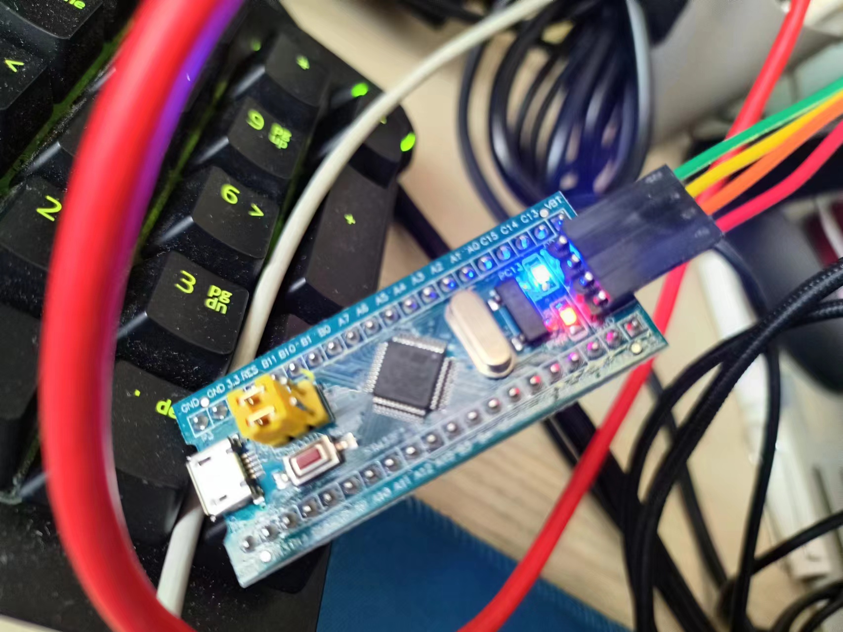
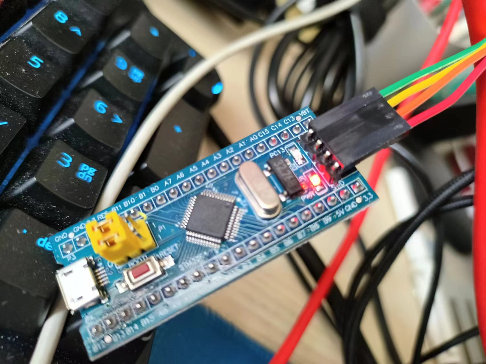
2.我们要配置寄存器来点灯,也就是pc13这个灯
(1)需要用RCC的一个寄存器来使能GPIOC的时钟,而GPIO都是APB2的外设
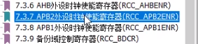
查看参考手册:
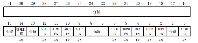
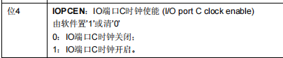
可以看到如果要打开GPIOC的时钟,我们需要将位4置1,所以这一位写1,其他位都为0,二进制转换为十六进制,也就是0 0 0 0 0 0 1 0 (四个位一分组)
也就是:
RCC->APB2ENR = 0x00000010;(2)第二个寄存器需要配置PC13口的模式

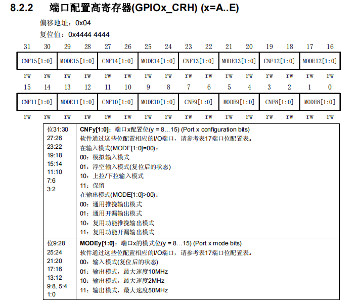
其中的CNF13和MODE13就是配置13号口的
CNF13需要配置为通用推挽输出模式,也就是00,推挽输出是指既可以输出低电平,也可以输出高电平,可以直接驱动功耗不大的数字器件。
MODE13要配置为输出模式,最大速度50MHz,也就是11
这样子换算成十六进制就是 0 0 3 0 0 0 0 0(四个位分一组)
GPIOC->CRH= 0x00300000;(3)给PC13口输出数据

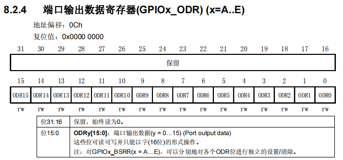
我们需要将ODR13口置1,13号口高电平,换算成十六进制也就是 0 0 0 0 2 0 0 0
GPIOC->ODR= 0x00002000;这个灯是低电平点亮,所以ODR全0就是亮,而 0 0 0 0 2 0 0 0就是灭
↑ODR全0
↑ODR为00002000
		//寄存器配置
		RCC->APB2ENR = 0x00000010;
		GPIOC->CRH = 0x00300000;
		GPIOC->ODR = 0x00002000;
库函数配置
与寄存器类似的步骤
1.需要一个函数使能时钟
这个函数是:
void RCC_APB2PeriphClockCmd(uint32_t RCC_APB2Periph, FunctionalState NewState)查看它的定义,它是用来使能或者失能APB2的外设时钟,可以发现它有两个参数
/**
  * @brief  Enables or disables the High Speed APB (APB2) peripheral clock.
  * @param  RCC_APB2Periph: specifies the APB2 peripheral to gates its clock.
  *   This parameter can be any combination of the following values:
  *     @arg RCC_APB2Periph_AFIO, RCC_APB2Periph_GPIOA, RCC_APB2Periph_GPIOB,
  *          RCC_APB2Periph_GPIOC, RCC_APB2Periph_GPIOD, RCC_APB2Periph_GPIOE,
  *          RCC_APB2Periph_GPIOF, RCC_APB2Periph_GPIOG, RCC_APB2Periph_ADC1,
  *          RCC_APB2Periph_ADC2, RCC_APB2Periph_TIM1, RCC_APB2Periph_SPI1,
  *          RCC_APB2Periph_TIM8, RCC_APB2Periph_USART1, RCC_APB2Periph_ADC3,
  *          RCC_APB2Periph_TIM15, RCC_APB2Periph_TIM16, RCC_APB2Periph_TIM17,
  *          RCC_APB2Periph_TIM9, RCC_APB2Periph_TIM10, RCC_APB2Periph_TIM11
  * @param  NewState: new state of the specified peripheral clock.
  *   This parameter can be: ENABLE or DISABLE.
  * @retval None
  */
第一项选GPIOC,我们直接从上面的参数进行复制即可,第二个参数选ENABLE(使能)
void RCC_APB2PeriphClockCmd(uint32_t RCC_APB2Periph, FunctionalState NewState)
{
  /* Check the parameters */
  assert_param(IS_RCC_APB2_PERIPH(RCC_APB2Periph));
  assert_param(IS_FUNCTIONAL_STATE(NewState));
  if (NewState != DISABLE)
  {
    RCC->APB2ENR |= RCC_APB2Periph;
  }
  else
  {
    RCC->APB2ENR &= ~RCC_APB2Periph;
  }
}
这个函数其实还是在配置RCC_APB2ENR这个寄存器,但是函数包装之后我们不需要查手册确认哪一位是在干什么了,而且它使用&=和|=来操作,不会影响寄存器其他位,这就是库函数和寄存器的区别
可以看出库函数更加方便
2.配置端口模式
(1)使用函数:
void GPIO_Init(GPIO_TypeDef* GPIOx, GPIO_InitTypeDef* GPIO_InitStruct)查看定义:
/**
  * @brief  Initializes the GPIOx peripheral according to the specified
  *         parameters in the GPIO_InitStruct.
  * @param  GPIOx: where x can be (A..G) to select the GPIO peripheral.
  * @param  GPIO_InitStruct: pointer to a GPIO_InitTypeDef structure that
  *         contains the configuration information for the specified GPIO peripheral.
  * @retval None
  */
第一个参数GPIOx,x为A到G,选择你要配置哪个GPIO,我们选GPIOC
第二个参数是一个结构体,所以我们需要自己先定义一个结构体
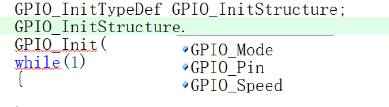
这个结构体的三个参数分别是GPIO模式,端口,速度
(2)查看这些参数的定义:
typedef struct
{
  uint16_t GPIO_Pin;             /*!< Specifies the GPIO pins to be configured.
                                      This parameter can be any value of @ref GPIO_pins_define */

  GPIOSpeed_TypeDef GPIO_Speed;  /*!< Specifies the speed for the selected pins.
                                      This parameter can be a value of @ref GPIOSpeed_TypeDef */

  GPIOMode_TypeDef GPIO_Mode;    /*!< Specifies the operating mode for the selected pins.
                                      This parameter can be a value of @ref GPIOMode_TypeDef */
}GPIO_InitTypeDef;
发现他说这个参数可以写GPIOMode_TypeDef里面的值,选中这个字符,Ctrl+F,搜索这个定义的位置
(3)找到GPIOMode_TypeDef定义:
typedef enum
{ GPIO_Mode_AIN = 0x0,
  GPIO_Mode_IN_FLOATING = 0x04,
  GPIO_Mode_IPD = 0x28,
  GPIO_Mode_IPU = 0x48,
  GPIO_Mode_Out_OD = 0x14,
  GPIO_Mode_Out_PP = 0x10,
  GPIO_Mode_AF_OD = 0x1C,
  GPIO_Mode_AF_PP = 0x18
}GPIOMode_TypeDef;
其中 GPIO_Mode_Out_PP就是通用推挽输出,我们选择它
GPIO_InitStructure.GPIO_Mode = GPIO_Mode_Out_PP;(4)查找Pin定义
查看pin的定义时发现有多个定义,选择类型为member的:
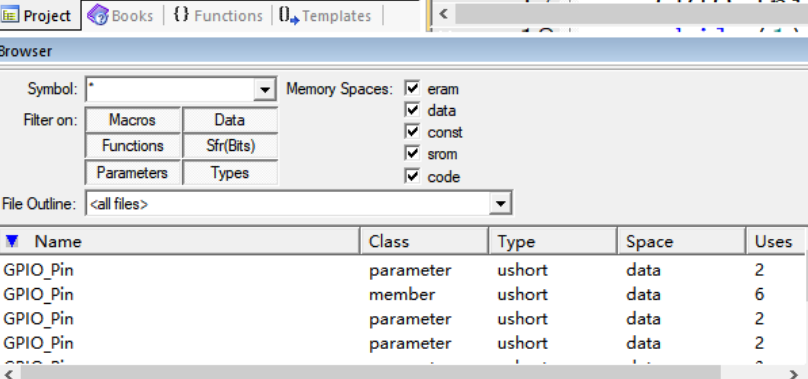
它的值可以取GPIO_pins_define的,我们搜索可得到有这些:
#define GPIO_Pin_0                 ((uint16_t)0x0001)  /*!< Pin 0 selected */
#define GPIO_Pin_1                 ((uint16_t)0x0002)  /*!< Pin 1 selected */
#define GPIO_Pin_2                 ((uint16_t)0x0004)  /*!< Pin 2 selected */
#define GPIO_Pin_3                 ((uint16_t)0x0008)  /*!< Pin 3 selected */
#define GPIO_Pin_4                 ((uint16_t)0x0010)  /*!< Pin 4 selected */
#define GPIO_Pin_5                 ((uint16_t)0x0020)  /*!< Pin 5 selected */
#define GPIO_Pin_6                 ((uint16_t)0x0040)  /*!< Pin 6 selected */
#define GPIO_Pin_7                 ((uint16_t)0x0080)  /*!< Pin 7 selected */
#define GPIO_Pin_8                 ((uint16_t)0x0100)  /*!< Pin 8 selected */
#define GPIO_Pin_9                 ((uint16_t)0x0200)  /*!< Pin 9 selected */
#define GPIO_Pin_10                ((uint16_t)0x0400)  /*!< Pin 10 selected */
#define GPIO_Pin_11                ((uint16_t)0x0800)  /*!< Pin 11 selected */
#define GPIO_Pin_12                ((uint16_t)0x1000)  /*!< Pin 12 selected */
#define GPIO_Pin_13                ((uint16_t)0x2000)  /*!< Pin 13 selected */
#define GPIO_Pin_14                ((uint16_t)0x4000)  /*!< Pin 14 selected */
#define GPIO_Pin_15                ((uint16_t)0x8000)  /*!< Pin 15 selected */
#define GPIO_Pin_All               ((uint16_t)0xFFFF)  /*!< All pins selected */
我们选择pin13
GPIO_InitStructure.GPIO_Pin = GPIO_Pin_13;
(5)查找speed定义
搜索speed的定义可得到:
typedef enum
{
  GPIO_Speed_10MHz = 1,
  GPIO_Speed_2MHz,
  GPIO_Speed_50MHz
}GPIOSpeed_TypeDef;
选择50MHz
GPIO_InitStructure.GPIO_Speed = GPIO_Speed_50MHz;最终结构体三个参数填写如下:
		GPIO_InitTypeDef GPIO_InitStructure;
		GPIO_InitStructure.GPIO_Mode = GPIO_Mode_Out_PP;
		GPIO_InitStructure.GPIO_Pin = GPIO_Pin_13;
		GPIO_InitStructure.GPIO_Speed = GPIO_Speed_50MHz;
(6)填写GPIO_Init函数第二个参数
又因为GPIO_Init函数第二个参数是一个指向结构体的指针
void GPIO_Init(GPIO_TypeDef* GPIOx, GPIO_InitTypeDef* GPIO_InitStruct)所以我们要传递结构体地址:在结构体名字前加上取址符&即可
GPIO_Init(GPIOC,&GPIO_InitStructure);3.最后设置端口的高低电平进行点灯
(1)使用函数GPIO_SetBits()把指定端口设置为高电平:
/**
  * @brief  Sets the selected data port bits.
  * @param  GPIOx: where x can be (A..G) to select the GPIO peripheral.
  * @param  GPIO_Pin: specifies the port bits to be written.
  *   This parameter can be any combination of GPIO_Pin_x where x can be (0..15).
  * @retval None
  */
void GPIO_SetBits(GPIO_TypeDef* GPIOx, uint16_t GPIO_Pin)
按照参数定义填写
GPIO_SetBits(GPIOC,GPIO_Pin_13);
(2)使用函数GPIO_ResetBits()把指定端口设置为低电平:
参数和上面的一样
GPIO_ResetBits(GPIOC,GPIO_Pin_13);
测试发现,13号口高电平则灯灭,低电平则灯亮
		//库函数配置
		RCC_APB2PeriphClockCmd(RCC_APB2Periph_GPIOC,ENABLE);
		GPIO_InitTypeDef GPIO_InitStructure;
		GPIO_InitStructure.GPIO_Mode = GPIO_Mode_Out_PP;
		GPIO_InitStructure.GPIO_Pin = GPIO_Pin_13;
		GPIO_InitStructure.GPIO_Speed = GPIO_Speed_50MHz;
		GPIO_Init(GPIOC,&GPIO_InitStructure);

		//GPIO_SetBits(GPIOC,GPIO_Pin_13); //高电平

		GPIO_ResetBits(GPIOC,GPIO_Pin_13); //低电平
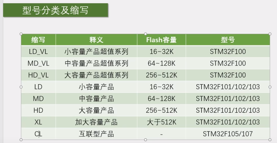
STM32的型号分类及缩写
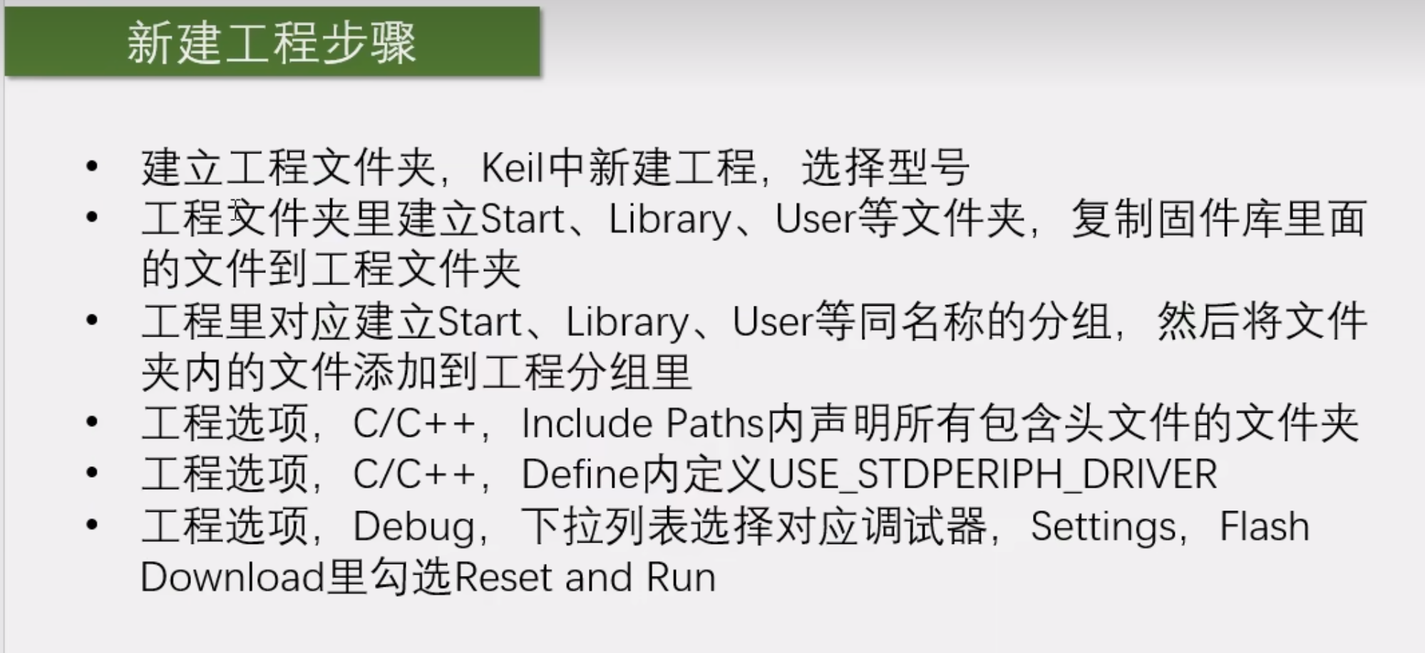
新建工程步骤


 126
126


 被折叠的 条评论
为什么被折叠?
被折叠的 条评论
为什么被折叠?
 到【灌水乐园】发言


