


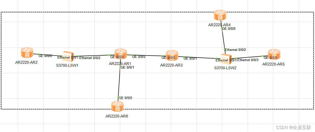
 文章详细介绍了IPv6环境下的路由协议配置,包括RIPng、OSPFv3的区域划分,以及虚链路解决非直连区域问题。同时,讨论了ISIS和BGP的配置,以及MTU对分片影响的测试。内容涵盖了网络设备间路由信息的传递和网络层次结构的设计。
AR1:interface GigabitEthernet0/0/1
ipv6 enable
ipv6 address 2016::2/64
ripng 1 enable
interface GigabitEthernet0/0/2
ipv6 enable
ipv6 address 2013::1/64
ripng 1 enable
interface LoopBack0
ipv6 enable
ipv6 address 2011::1/64
ripng 1 enable
ripng 1
其余类似
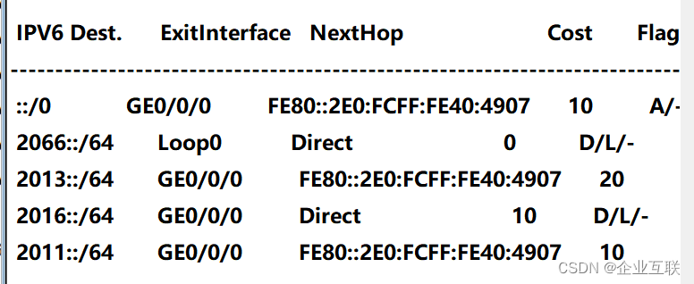
查看路由
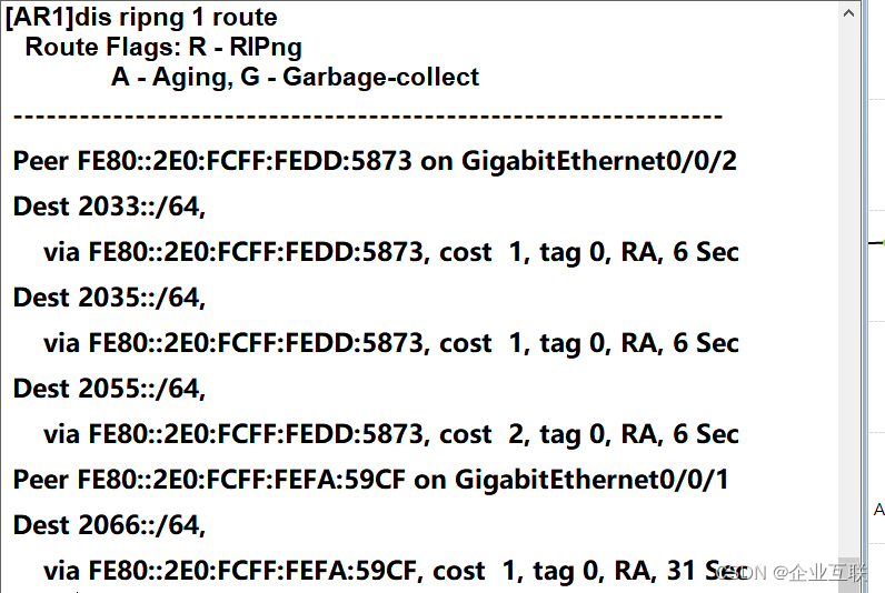
报文结构

请求报文和回应报文
请求报文使用组播获取
回应使用单播用的link-local地址,会带有路由信息,让R1获取路由

在接口上更改path MTU可通过的数量
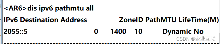
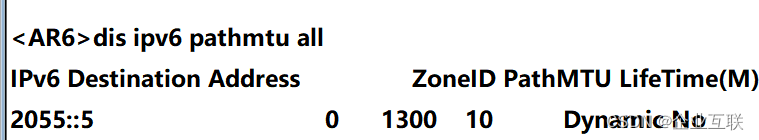
可以看到虽然将接口的可通过的MTU降低,但是IPv6会进行分片处理
到最后会由分片的ping进行测试,会分出包来为通过接口的MTU
OSPFV3
和ripng配置基本相同
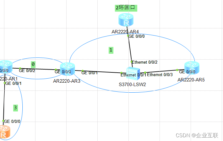
区域划分
AR1命令:
interface GigabitEthernet0/0/1
ipv6 enable
ipv6 address 2016::1/64
ospfv3 1 area 0.0.0.3
interface GigabitEthernet0/0/2
ipv6 enable
ipv6 address 2013::1/64
ospfv3 1 area 0.0.0.0
interface LoopBack0
ipv6 enable
ipv6 address 2011::1/64
ospfv3 1 area 0.0.0.0
ospfv3 1
router-id 10.1.1.1
其余路由器和R1类似
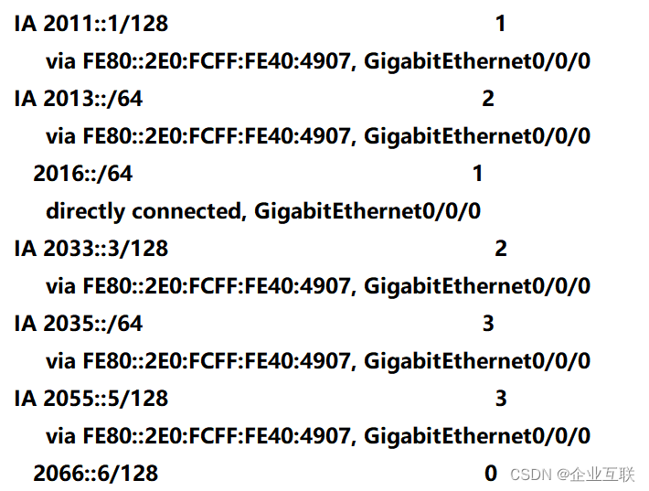
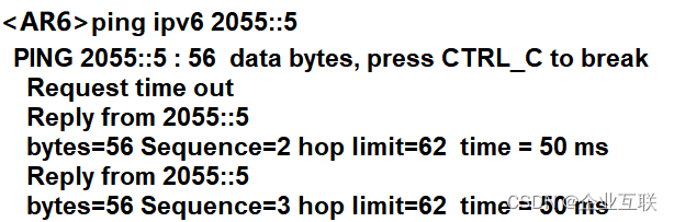
查看R6的路由表,进行PING测试
但是没有R4的环回路由,是因为没有和核心区域对接,所以需要配置虚链路
在R3和R4配置虚链路
ospfv3 1
router-id 10.1.3.3
area 0.0.0.1
vlink-peer 10.1.4.4
#
ospfv3 1
router-id 10.1.4.4
area 0.0.0.1
vlink-peer 10.1.3.3

R6有了2044的路由
查看虚链路状态
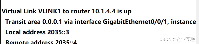 UP源ip和对端ip还有创建虚链路的接口
配置ISIS和BGP for IPV6
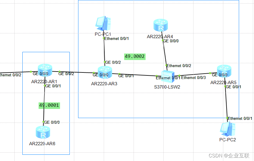
R1和R6在isis区域49.0001 R3 R4 和R5在isis区域49.0002
依旧是以R1为例
sysname AR1
ipv6
isis 1
network-entity 49.0001.0000.0000.1111.00
ipv6 enable topology standard
interface GigabitEthernet0/0/1
ipv6 enable
ipv6 address 2016::1/64
isis ipv6 enable 1
interface GigabitEthernet0/0/2
ipv6 enable
ipv6 address 2013::1/64
isis ipv6 enable 1
interface LoopBack0
ipv6 enable
ipv6 address 2011::1/64
isis ipv6 enable 1
在查看R6的isis邻居和路由
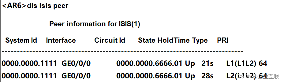
L1
L2
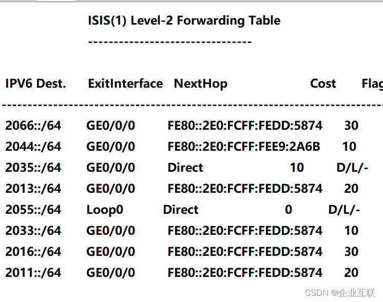
修改AR6的的isis路由为L1,修改AR3和AR4和AR5的isis路由器类型为L2
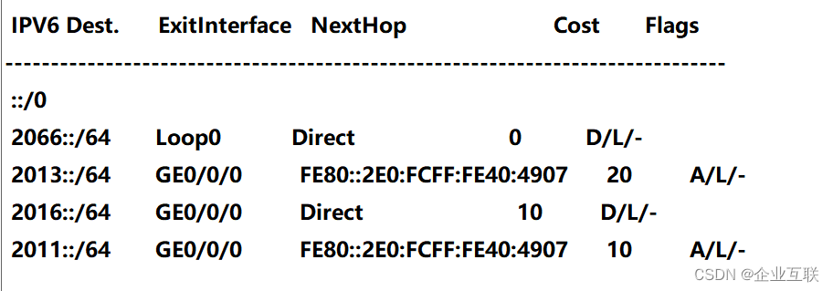
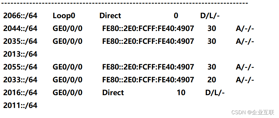
然后R6的路由表就只有L1的 R3 R4 R5的路由表只有L2的,但是L2的路由表包含所有路由
L1的路由表只有区域内的,但是有一条通往外界的默认路由
R6:
R5:
配置BGP for IPV6
R1: bgp 100
router-id 10.1.1.1
peer 2033::3 as-number 100
peer 2033::3 connect-interface LoopBack0
ipv6-family unicast
undo synchronization
network 2066:: 64
peer 2033::3 enable
R3:bgp 100
router-id 10.1.3.3
peer 2011::1 as-number 100
peer 2011::1 connect-interface LoopBack0
ipv6-family unicast
undo synchronization
network 2055:: 64
peer 2011::1 enable
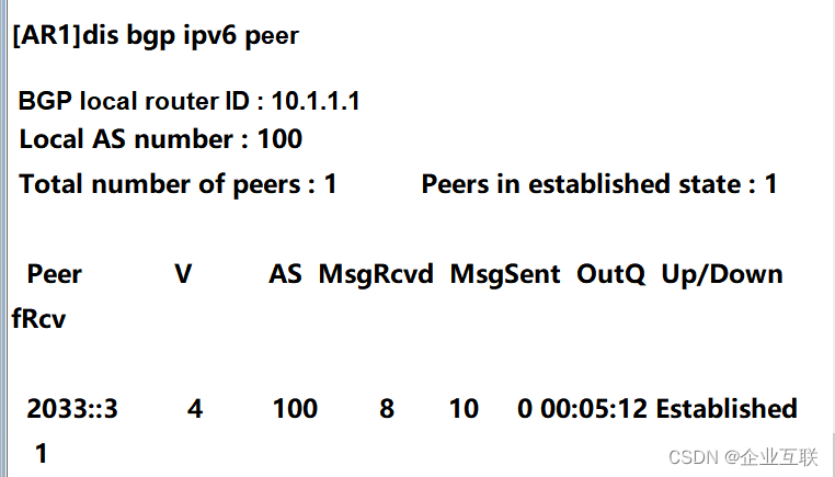
查看BGP的邻居关系
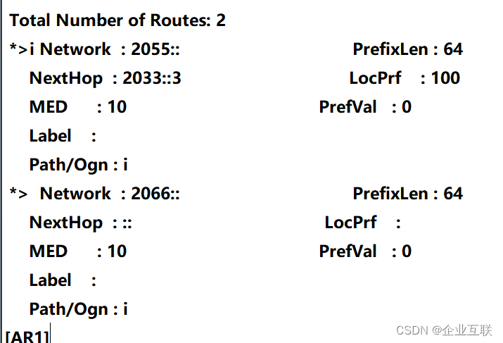
查看路由


 被折叠的 条评论
为什么被折叠?
被折叠的 条评论
为什么被折叠?
 到【灌水乐园】发言


