


文章目录
一.高级定时器输出配置问题
1.用高级定时器TIM1/TIM8输出PWM波时,必须将其OC配置完整!!!!
//TIM_OCStructInit(&TIM_OCInitStructure); //初始化Pwm通道TIM8_CH_OC1/2/3/4——并且全部配置!!! //或者在前面使用TIM_OCStructInit(&TIM_OCInitStructure); TIM_OCStructInit(&TIM_OCInitStructure); TIM_OCInitStructure.TIM_Pulse = 0; //设置待装入捕获比较寄存器冲值为0 TIM_OCInitStructure.TIM_OCMode = TIM_OCMode_PWM1; //设置PWm模式1 CNT<CCR为有效电平 TIM_OCInitStructure.TIM_OCPolarity = TIM_OCPolarity_High; //设置有效电平输出极性为高极性 TIM_OCInitStructure.TIM_OutputState = TIM_OutputState_Enable; //使能输出比较状态使能输出到端口 TIM_OCInitStructure.TIM_OutputNState = TIM_OutputNState_Enable; //使能输出比较N状态 TIM_OCInitStructure.TIM_OCIdleState = TIM_OCIdleState_Reset; //当 MOE=0 重置 TIM1 输出比较空闲状态 TIM_OCInitStructure.TIM_OCNIdleState = TIM_OCNIdleState_Reset; //当 MOE=0 重置 TIM1 输出比较 N 空闲状态 TIM_OCInitStructure.TIM_OCNPolarity = TIM_OCNPolarity_High; //TIM1 输出比较N极性高 TIM_OC1Init(TIM8,&TIM_OCInitStructure);//配置TIM8的四个通道输出PWM TIM_OC2Init(TIM8,&TIM_OCInitStructure); TIM_OC3Init(TIM8,&TIM_OCInitStructure); TIM_OC4Init(TIM8,&TIM_OCInitStructure); 配置完成之后pwm才能正常输出!!
二.仿真调试
1.数据不能实时更新的问题
解决方法:打开调试之后-->点击view-->最后的update勾选。(之后watch里的输出变量就能实时更新啦!!)
注意:watch里面的变量当然是全局变量才能监测!!!
三.闭环的代码问题
有篇文章还是不错的https://blog.csdn.net/qq_44343584/article/details/122318756
pwm.h
#ifndef __PWM_H
#define __PWM_H
#include "sys.h"
void PWM_Init_TIM8(u16 arr, u16 psc);
void change_pwm(u16 i);

#define AIN2   PBout(12)
#define AIN1   PBout(13)
#define BIN1   PBout(14)
#define BIN2   PBout(15)
#define ain2   PEout(12)
#define ain1   PEout(13)
#define bin1   PEout(14)
#define bin2   PEout(15)


#endif
pwm.c
#include "pwm.h"
//#include "Device/Include/stm32f10x.h"   // Device header


void PWM_Init_TIM8(u16 arr, u16 psc)
{

	GPIO_InitTypeDef GPIO_InitStructure;	 //定义一个引脚初始化的结构体
	TIM_TimeBaseInitTypeDef TIM_TimeBaseInitStrue; //定义一个定时中断的结构体
	TIM_OCInitTypeDef TIM_OCInitStructure; //定义一个 PWM 输出的结构

	RCC_APB2PeriphClockCmd(RCC_APB2Periph_GPIOC|RCC_APB2Periph_TIM8|RCC_APB2Periph_GPIOE,
    ENABLE);//PB/E控制电机IO,TIM8控制pwm输出引脚
	//控制方向引脚
	GPIO_InitStructure.GPIO_Pin=GPIO_Pin_12|GPIO_Pin_13|GPIO_Pin_14|GPIO_Pin_15;
	GPIO_InitStructure.GPIO_Mode=GPIO_Mode_Out_PP; //引脚输入输出模式为推挽输出模式
	GPIO_InitStructure.GPIO_Speed=GPIO_Speed_50MHz; //引脚输出速度为 50MHZ
	GPIO_Init(GPIOB,&GPIO_InitStructure);//根据上面设置好的GPIO_InitStructure参数初始化引脚

	GPIO_InitStructure.GPIO_Pin=GPIO_Pin_12|GPIO_Pin_13|GPIO_Pin_14|GPIO_Pin_15;
	GPIO_InitStructure.GPIO_Mode=GPIO_Mode_Out_PP; //引脚输入输出模式为推挽输出模式
	GPIO_InitStructure.GPIO_Speed=GPIO_Speed_50MHz; //引脚输出速度为 50MHZ
	GPIO_Init(GPIOE, &GPIO_InitStructure);//根据上面设置好的GPIO_InitStructure参数初始化引脚
	//pwm引脚
	GPIO_InitStructure.GPIO_Pin = GPIO_Pin_6|GPIO_Pin_7|GPIO_Pin_8|GPIO_Pin_9;
	GPIO_InitStructure.GPIO_Mode = GPIO_Mode_AF_PP;
	GPIO_InitStructure.GPIO_Speed = GPIO_Speed_50MHz;
	GPIO_Init(GPIOC, &GPIO_InitStructure);

	//初始化高级定时器TIM8
	TIM_TimeBaseInitStrue.TIM_Period=arr;
    //自动重装载值
	TIM_TimeBaseInitStrue.TIM_Prescaler=psc;
    //预分频系数
	TIM_TimeBaseInitStrue.TIM_ClockDivision=TIM_CKD_DIV1;	//
	TIM_TimeBaseInitStrue.TIM_CounterMode=TIM_CounterMode_Up//向上计数
	TIM_TimeBaseInit(TIM8,&TIM_TimeBaseInitStrue);

	//初始化Pwm通道TIM8_CH_OC1/2/3/4
	TIM_OCInitStructure.TIM_Pulse = 0;//设置待装入捕获比较寄存器的脉冲值
	TIM_OCInitStructure.TIM_OCMode = TIM_OCMode_PWM1;
	TIM_OCInitStructure.TIM_OCPolarity = TIM_OCPolarity_High;
	TIM_OCInitStructure.TIM_OutputState = TIM_OutputState_Enable;  //使能输出比较状态   //
    使能输出到端口
	TIM_OCInitStructure.TIM_OutputNState = TIM_OutputNState_Enable;//使能输出比较N状态
	TIM_OCInitStructure.TIM_OCIdleState = TIM_OCIdleState_Reset;//当 MOE=0 重置 TIM1 输出
    比较空闲状态
	TIM_OCInitStructure.TIM_OCNIdleState = TIM_OCNIdleState_Reset;//当 MOE=0 重置 TIM1 输
    出比较 N 空闲状态
	TIM_OCInitStructure.TIM_OCNPolarity = TIM_OCNPolarity_High;//TIM1 输出比较N极性高
	TIM_OC1Init(TIM8,&TIM_OCInitStructure);
    TIM_OC2Init(TIM8,&TIM_OCInitStructure);
	TIM_OC3Init(TIM8,&TIM_OCInitStructure);
    TIM_OC4Init(TIM8,&TIM_OCInitStructure);

	//使能TIM8在CCR1上的预装载寄存器
	TIM_OC1PreloadConfig(TIM8, TIM_OCPreload_Enable);
	TIM_OC2PreloadConfig(TIM8, TIM_OCPreload_Enable);
	TIM_OC3PreloadConfig(TIM8, TIM_OCPreload_Enable);
	TIM_OC4PreloadConfig(TIM8, TIM_OCPreload_Enable);

	TIM_CtrlPWMOutputs(TIM8,ENABLE);//高级定时器的使能函数
	TIM_ARRPreloadConfig(TIM8,ENABLE);//使能TIM8 ARR上的预装载寄存器
	TIM_Cmd(TIM8, ENABLE);//使能TIM8

}
注意:
1. TIM_CtrlPWMOutputs(TIM8,ENABLE);//配置高级定时器这一句必须有!!
2.配置高级定时器需要将TIM_OC1Init()函数的结构体成员全部赋初值!!!否则无法运行
(可以在新建的结构体数据类型变量下面使用TIM_OCStructInit(&TIM_OCInitStructure))
encoder.h(编码器)
#ifndef __ENCODER_H
#define __ENCODER_H
#include "sys.h"
#include "pwm.h"
extern int Encoder_TIM;
void Encoder_Init_TIM2(void);
void Encoder_Init_TIM3(void);
void Encoder_Init_TIM4(void);
void Encoder_Init_TIM5(void);
void Encoder_Init_TIM(void);
int Read_Encoder(u8 TIMX);
#endif
encoder.c
#include "encoder.h"
//#include "Device/Include/stm32f10x.h"// Device header

void Encoder_Init_TIM2(void)
{
//	GPIO_InitTypeDef GPIO_InitStructure;//初始化GPIO-->PA0/PA1
//	TIM_TimeBaseInitTypeDef TIM_TimeBaseInitStruct;
//	TIM_ICInitTypeDef TIM_ICInitStruct;


//
//	RCC_APB2PeriphClockCmd(RCC_APB2Periph_GPIOA,ENABLE);//使能GPIOA时钟
//	RCC_APB1PeriphClockCmd(RCC_APB1Periph_TIM2, ENABLE);//使能TIM2_CH1/2-->PA0/1
//
//	GPIO_InitStructure.GPIO_Mode=GPIO_Mode_IN_FLOATING;
//	GPIO_InitStructure.GPIO_Pin=GPIO_Pin_0|GPIO_Pin_1;
//	GPIO_InitStructure.GPIO_Speed=GPIO_Speed_50MHz;
//	GPIO_Init(GPIOA,&GPIO_InitStructure);

//以上是发现了TIM2和TIM5的CH1和CH2的IO冲突了使用重映射了TIM2的通道


	TIM_TimeBaseInitTypeDef TIM_TimeBaseInitStruct;
	TIM_ICInitTypeDef TIM_ICInitStruct;
	GPIO_InitTypeDef GPIO_InitStructure;

	RCC_APB2PeriphClockCmd(RCC_APB2Periph_AFIO|RCC_APB2Periph_GPIOA|RCC_APB2Periph_GPIOB,
    ENABLE);
	RCC_APB1PeriphClockCmd(RCC_APB1Periph_TIM2, ENABLE);
	GPIO_PinRemapConfig(GPIO_FullRemap_TIM2 ,ENABLE );
	GPIO_PinRemapConfig(GPIO_Remap_SWJ_JTAGDisable,ENABLE);//重映射TIM2就要禁用这个IO


	GPIO_InitStructure.GPIO_Pin =  GPIO_Pin_15;
    GPIO_InitStructure.GPIO_Mode = GPIO_Mode_IN_FLOATING;
    GPIO_Init(GPIOA, &GPIO_InitStructure);

	GPIO_InitStructure.GPIO_Pin =  GPIO_Pin_3;
    GPIO_InitStructure.GPIO_Mode = GPIO_Mode_IN_FLOATING;
    GPIO_Init(GPIOB, &GPIO_InitStructure);


	//初始化TIM2
	TIM_TimeBaseInitStruct.TIM_CounterMode = TIM_CounterMode_Up;//TIM向上计数模式
	TIM_TimeBaseInitStruct.TIM_Period = 65534;//配置自动重装载寄存器的值
	TIM_TimeBaseInitStruct.TIM_Prescaler = 0;//配置定时器时钟分频
	TIM_TimeBaseInitStruct.TIM_ClockDivision = TIM_CKD_DIV1;	//时钟分频
	TIM_TimeBaseInitStruct.TIM_RepetitionCounter=0;	//重复计数器无效0
	TIM_TimeBaseInit(TIM2, &TIM_TimeBaseInitStruct);

	//配置输入通道一
	TIM_ICInitStruct.TIM_Channel = TIM_Channel_1;
	TIM_ICInitStruct.TIM_ICPrescaler = TIM_ICPSC_DIV1;	//输入器不分频
	TIM_ICInitStruct.TIM_ICPolarity = TIM_ICPolarity_Rising;	//上升沿捕获
	TIM_ICInitStruct.TIM_ICSelection = TIM_ICSelection_DirectTI;	//映射到IC1
	TIM_ICInitStruct.TIM_ICFilter = 0;	//不滤波
	TIM_ICInit(TIM2, &TIM_ICInitStruct);
	//初始化通道二
	TIM_ICInitStruct.TIM_Channel = TIM_Channel_2;
	TIM_ICInitStruct.TIM_ICPrescaler = TIM_ICPSC_DIV1;
	TIM_ICInitStruct.TIM_ICPolarity = TIM_ICPolarity_Rising;
	TIM_ICInitStruct.TIM_ICSelection = TIM_ICSelection_DirectTI;
	TIM_ICInitStruct.TIM_ICFilter = 0;
	TIM_ICInit(TIM2, &TIM_ICInitStruct);

	TIM_EncoderInterfaceConfig(TIM2, TIM_EncoderMode_TI12, TIM_ICPolarity_Rising, TIM_ICPolarity_Rising);	//使用编码器模式 3:CH1、CH2 同时计数,为四分频

  TIM_ClearFlag(TIM2, TIM_FLAG_Update);			//清理更新标志位
  //TIM_ITConfig(TIM2, TIM_IT_Update, ENABLE);//使能更新中断


	TIM_SetCounter(TIM2,0);										//将CNT置零

	TIM_Cmd(TIM2, ENABLE);										//使能TIM2
}

//TIM3_CH1/2-->PA6/PA7
void Encoder_Init_TIM3(void)
{
	TIM_TimeBaseInitTypeDef TIM_TimeBaseInitStruct;
	TIM_ICInitTypeDef TIM_ICInitStruct;
	GPIO_InitTypeDef GPIO_InitStructure;

	RCC_APB2PeriphClockCmd(RCC_APB2Periph_GPIOA, ENABLE);
	RCC_APB1PeriphClockCmd(RCC_APB1Periph_TIM3, ENABLE);

	GPIO_InitStructure.GPIO_Pin =  GPIO_Pin_6|GPIO_Pin_7;
  GPIO_InitStructure.GPIO_Mode = GPIO_Mode_IN_FLOATING;
  GPIO_Init(GPIOA, &GPIO_InitStructure);


	//配置时基
	TIM_TimeBaseInitStruct.TIM_CounterMode = TIM_CounterMode_Up;
	//TIM向上计数模式
	TIM_TimeBaseInitStruct.TIM_Period = 65534;
	//配置自动重装载寄存器的值
	TIM_TimeBaseInitStruct.TIM_Prescaler = 0x0;
	//配置定时器时钟分频
	TIM_TimeBaseInitStruct.TIM_ClockDivision = TIM_CKD_DIV1;
	//时钟分频
	TIM_TimeBaseInitStruct.TIM_RepetitionCounter=0;
	//重复计数器无效0
	TIM_TimeBaseInit(TIM3, &TIM_TimeBaseInitStruct);

	//配置输入
	TIM_ICInitStruct.TIM_Channel = TIM_Channel_1;
	TIM_ICInitStruct.TIM_ICPrescaler = TIM_ICPSC_DIV1;	//输入器不分频
	TIM_ICInitStruct.TIM_ICPolarity = TIM_ICPolarity_Rising;	//上升沿捕获
	TIM_ICInitStruct.TIM_ICSelection = TIM_ICSelection_DirectTI;	//映射到IC1
	TIM_ICInitStruct.TIM_ICFilter = 0;	//不滤波
	TIM_ICInit(TIM3, &TIM_ICInitStruct);

	TIM_ICInitStruct.TIM_Channel = TIM_Channel_2;
	TIM_ICInitStruct.TIM_ICPrescaler = TIM_ICPSC_DIV1;
	TIM_ICInitStruct.TIM_ICPolarity = TIM_ICPolarity_Rising;
	TIM_ICInitStruct.TIM_ICSelection = TIM_ICSelection_DirectTI;
	TIM_ICInitStruct.TIM_ICFilter = 0;
	TIM_ICInit(TIM3, &TIM_ICInitStruct);

	TIM_EncoderInterfaceConfig(TIM3, TIM_EncoderMode_TI12, TIM_ICPolarity_Rising, TIM_ICPolarity_Rising);//使能编码器模式3 0x0003


  TIM_ClearFlag(TIM3, TIM_FLAG_Update);

	TIM_SetCounter(TIM3,0);

	TIM_Cmd(TIM3, ENABLE);
}


void Encoder_Init_TIM4(void)// PB6 PB7
{
	TIM_TimeBaseInitTypeDef TIM_TimeBaseInitStruct;
	TIM_ICInitTypeDef TIM_ICInitStruct;
	GPIO_InitTypeDef GPIO_InitStructure;

	RCC_APB2PeriphClockCmd(RCC_APB2Periph_GPIOB, ENABLE);
	RCC_APB1PeriphClockCmd(RCC_APB1Periph_TIM4, ENABLE);

	GPIO_InitStructure.GPIO_Pin =  GPIO_Pin_6 | GPIO_Pin_7;
  GPIO_InitStructure.GPIO_Mode = GPIO_Mode_IN_FLOATING;
  GPIO_Init(GPIOB, &GPIO_InitStructure);

	//配置时基
	TIM_TimeBaseInitStruct.TIM_CounterMode = TIM_CounterMode_Up;
	//TIM向上计数模式
	TIM_TimeBaseInitStruct.TIM_Period = 65534;
	//配置自动重装载寄存器的值
	TIM_TimeBaseInitStruct.TIM_Prescaler = 0x0;
	//配置定时器时钟分频
	TIM_TimeBaseInitStruct.TIM_ClockDivision = TIM_CKD_DIV1;
	//时钟分频
	TIM_TimeBaseInitStruct.TIM_RepetitionCounter=0;
	//重复计数器无效0
	TIM_TimeBaseInit(TIM4, &TIM_TimeBaseInitStruct);

	//配置输入
	TIM_ICInitStruct.TIM_Channel = TIM_Channel_1;
	TIM_ICInitStruct.TIM_ICPrescaler = TIM_ICPSC_DIV1;
	//输入器不分频
	TIM_ICInitStruct.TIM_ICPolarity = TIM_ICPolarity_Rising;
	//上升沿捕获
	TIM_ICInitStruct.TIM_ICSelection = TIM_ICSelection_DirectTI;
	//映射到IC1
	TIM_ICInitStruct.TIM_ICFilter = 0;
	//不滤波
	TIM_ICInit(TIM4, &TIM_ICInitStruct);

	TIM_ICInitStruct.TIM_Channel = TIM_Channel_2;
	TIM_ICInitStruct.TIM_ICPrescaler = TIM_ICPSC_DIV1;
	TIM_ICInitStruct.TIM_ICPolarity = TIM_ICPolarity_Rising;
	TIM_ICInitStruct.TIM_ICSelection = TIM_ICSelection_DirectTI;
	TIM_ICInitStruct.TIM_ICFilter = 0;
	TIM_ICInit(TIM4, &TIM_ICInitStruct);

	TIM_EncoderInterfaceConfig(TIM4, TIM_EncoderMode_TI12, TIM_ICPolarity_Rising, TIM_ICPolarity_Rising);
	//使能编码器模式3 0x0003

  TIM_ClearFlag(TIM4, TIM_FLAG_Update);

	TIM_SetCounter(TIM4,0);

	TIM_Cmd(TIM4, ENABLE);
}


void Encoder_Init_TIM5(void)//PA0 PA1
{
	TIM_TimeBaseInitTypeDef TIM_TimeBaseInitStruct;
	TIM_ICInitTypeDef TIM_ICInitStruct;
	GPIO_InitTypeDef GPIO_InitStructure;

	RCC_APB2PeriphClockCmd(RCC_APB2Periph_GPIOA, ENABLE);
	RCC_APB1PeriphClockCmd(RCC_APB1Periph_TIM5, ENABLE);

	GPIO_InitStructure.GPIO_Pin =  GPIO_Pin_0 | GPIO_Pin_1;
  GPIO_InitStructure.GPIO_Mode = GPIO_Mode_IN_FLOATING;
  GPIO_Init(GPIOA, &GPIO_InitStructure);

	//配置时基
	TIM_TimeBaseInitStruct.TIM_CounterMode = TIM_CounterMode_Up;
	//TIM向上计数模式
	TIM_TimeBaseInitStruct.TIM_Period = 65534;
	//配置自动重装载寄存器的值
	TIM_TimeBaseInitStruct.TIM_Prescaler = 0x0;
	//配置定时器时钟分频
	TIM_TimeBaseInitStruct.TIM_ClockDivision = TIM_CKD_DIV1;
	//时钟分频
	TIM_TimeBaseInitStruct.TIM_RepetitionCounter=0;
	//重复计数器无效0
	TIM_TimeBaseInit(TIM5, &TIM_TimeBaseInitStruct);

	//配置输入
	TIM_ICInitStruct.TIM_Channel = TIM_Channel_1;
	TIM_ICInitStruct.TIM_ICPrescaler = TIM_ICPSC_DIV1;
	//输入器不分频
	TIM_ICInitStruct.TIM_ICPolarity = TIM_ICPolarity_Rising;
	//上升沿捕获
	TIM_ICInitStruct.TIM_ICSelection = TIM_ICSelection_DirectTI;
	//映射到IC1
	TIM_ICInitStruct.TIM_ICFilter = 0;
	//不滤波
	TIM_ICInit(TIM5, &TIM_ICInitStruct);

	TIM_ICInitStruct.TIM_Channel = TIM_Channel_2;
	TIM_ICInitStruct.TIM_ICPrescaler = TIM_ICPSC_DIV1;
	TIM_ICInitStruct.TIM_ICPolarity = TIM_ICPolarity_Rising;
	TIM_ICInitStruct.TIM_ICSelection = TIM_ICSelection_DirectTI;
	TIM_ICInitStruct.TIM_ICFilter = 0;
	TIM_ICInit(TIM5, &TIM_ICInitStruct);

	TIM_EncoderInterfaceConfig(TIM5, TIM_EncoderMode_TI12, TIM_ICPolarity_Rising, TIM_ICPolarity_Rising);//使能编码器模式3 0x0003


  TIM_ClearFlag(TIM5, TIM_FLAG_Update);

	TIM_SetCounter(TIM5,0);

	TIM_Cmd(TIM5, ENABLE);
}
//编码器初始化
void Encoder_Init_TIM(void)
{
	Encoder_Init_TIM2();
	Encoder_Init_TIM3();
	Encoder_Init_TIM4();
	Encoder_Init_TIM5();
}
//int Encoder_TIM;
//读取不同定时器编码器的CNT值
int Read_Encoder(u8 TIMX)
{
   int Encoder_TIM;
   switch(TIMX)
	 {
		 case 1:  Encoder_TIM= (short)TIM1 -> CNT;  TIM1 -> CNT=0;break;
	     case 2:  Encoder_TIM= (short)TIM2 -> CNT;  TIM2 -> CNT=0;break;
		 case 3:  Encoder_TIM= (short)TIM3 -> CNT;  TIM3 -> CNT=0;break;
		 case 4:  Encoder_TIM= (short)TIM4 -> CNT;  TIM4 -> CNT=0;break;
		 case 5:  Encoder_TIM= (short)TIM5 -> CNT;  TIM5 -> CNT=0;break;
		 case 8:  Encoder_TIM= (short)TIM8 -> CNT;  TIM8 -> CNT=0;break;
		 default: Encoder_TIM=0;
	 }
		return Encoder_TIM;    /*CNT清零*/
}
注意:
1.TIM2和TIM5的CH1和CH2重复,使用将TIM2使用了完全重映射!!!(也就是我一开始为什么在TIM2中注释掉那一大段的原因);
2.使用TIM2完全重映射的时候(根据《STM32中文参考手册》和《精英版IO原理图》)
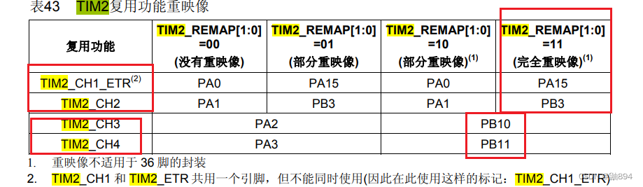
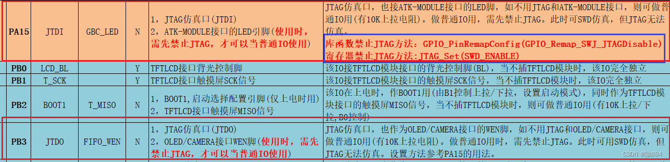
可以看出来原理图中有库函数禁止JTAG的方法!!!
pid.h
#ifndef __PID_H
#define __PID_H
#include "sys.h"
#include "pwm.h"
#include "encoder.h"
//定义一个pid的数据类型
typedef struct
{
	float Target; 			        //设定目标值
	float Measured; 				    //测量值
	float err; 									//本次偏差值
	float err_last; 			  	  //上一次偏差
	float err_beforeLast;
	float pwm; 									//pwm输出
}incrementalpid_t;

extern incrementalpid_t pid[4];
extern int Encoder1;
extern int Target1;
extern int Motor1;

extern int Encoder2;
extern int Target2;
extern int Motor2;

extern int Encoder3;
extern int Target3;
extern int Motor3;

extern int Encoder4;
extern int Target4;
extern int Motor4;
int Incremental_PID1(int Encoder1,int Target1);
int Incremental_PID2(int Encoder2,int Target2);
int Incremental_PID3(int Encoder3,int Target3);
int Incremental_PID4(int Encoder4,int Target4);
void Set_Pwm1(int moto1);
void Set_Pwm2(int moto2);
void Set_Pwm3(int moto3);
void Set_Pwm4(int moto4);
int myabs(int a); //取绝对值

#endif
注意:这里将pid算法中的变量用结构体定义了一个数据类型!!!
下面是重点!!!
pid.c
#include "pid.h"
//#include "Device/Include/stm32f10x.h"   // Device header
#define PI 3.14159265

incrementalpid_t pid[4];
float Kp1=9, Ki1=0.8,Kd1=0;				        //Kp, Ki,Kd控制系数
float Kp2=9, Ki2=0.7,Kd2=0;				        //Kp, Ki,Kd控制系数
float Kp3=9, Ki3=0.8,Kd3=0;				        //Kp, Ki,Kd控制系数
float Kp4=9, Ki4=0.7,Kd4=0;		 		        //Kp, Ki,Kd控制系数
int Motor1;
int Encoder1;
int Motor2;
int Encoder2;
int Motor3;
int Encoder3;
int Motor4;
int Encoder4;
int Target1;
int Target2;
int Target3;
int Target4;

/**************************************************************************
函数功能:增量PI控制器
入口参数:编码器测量值,目标速度
返回  值:电机PWM
根据增量式离散PID公式
pwm+=Kp[e(k)-e(k-1)]+Ki*e(k)+Kd[e(k)-2e(k-1)+e(k-2)]
e(k)代表本次偏差
e(k-1)代表上一次的偏差  以此类推
pwm代表增量输出
在我们的速度控制闭环系统里面,只使用PI控制
pwm+=Kp[e(k)-e(k-1)]+Ki*e(k)
**************************************************************************/
int Incremental_PID1(int Encoder1,int Target1)
{
	pid[0].err=Target1-Encoder1;                //计算偏差
	pid[0].pwm+=Kp1*(pid[0].err-pid[0].err_last)+Ki1*pid[0].err+Kd1*(pid[0].err-
    2*pid[0].err_last+pid[0].err_beforeLast);   //增量式PID控制器
    //===PWM满幅是7200 限制在7100
	if(pid[0].pwm<-7000)
    pid[0].pwm = -7000;
    else if(pid[0].pwm>7000)
    pid[0].pwm =  7000;
	pid[0].err_beforeLast=pid[0].err_last;
	pid[0].err_last=pid[0].err;	                   //保存上一次偏差
	return pid[0].pwm;                         //增量输出
}
int Incremental_PID2(int Encoder2,int Target2)
{
	pid[1].err=Target2-Encoder2;                //计算偏差
	pid[1].pwm+=Kp2*(pid[1].err-pid[1].err_last)+Ki2*pid[1].err+Kd2*(pid[1].err-
    2*pid[1].err_last+pid[1].err_beforeLast);   //增量式PID控制器
         //===PWM满幅是7200 限制在7100
	 if(pid[1].pwm<-7000)
		 pid[1].pwm = -7000;
	 else if(pid[1].pwm>7000)
		 pid[1].pwm =  7000;
	 pid[1].err_beforeLast=pid[1].err_last;
		pid[1].err_last=pid[1].err;	                   //保存上一次偏差
	return pid[1].pwm;                         //增量输出
}
int Incremental_PID3(int Encoder3,int Target3)
{
	pid[2].err=Target3-Encoder3;                //计算偏差
	pid[2].pwm+=Kp3*(pid[2].err-pid[2].err_last)+Ki3*pid[2].err+Kd3*(pid[2].err-
    2*pid[2].err_last+pid[2].err_beforeLast);   //增量式PID控制器
    //===PWM满幅是7200 限制在7100
	if(pid[2].pwm<-7000)
    pid[2].pwm = -7000;
	else if(pid[2].pwm>7000)
	pid[2].pwm =  7000;
	pid[2].err_beforeLast=pid[2].err_last;
	pid[2].err_last=pid[2].err;	                   //保存上一次偏差
	return pid[2].pwm;                         //增量输出
}
int Incremental_PID4(int Encoder4,int Target4)
{
	pid[3].err=Target4-Encoder4 //计算偏差
	pid[3].pwm+=Kp4*(pid[3].err-pid[3].err_last)+Ki4*pid[3].err+Kd4*(pid[3].err-
    2*pid[3].err_last+pid[3].err_beforeLast);//增量式PID控制器
    //===PWM满幅是7200 限制在7100
	if(pid[3].pwm<-7000)
	pid[3].pwm = -7000;
	else if(pid[3].pwm>7000)
	pid[3].pwm =  7000;
	pid[3].err_beforeLast=pid[3].err_last;
	pid[3].err_last=pid[3].err;	                   //保存上一次偏差
	return pid[3].pwm;                         //增量输出
}


void Set_Pwm1(int moto1)//赋值给PWM寄存器
{
 if(moto1>0) AIN1=0,   AIN2=1;
	else      AIN1=1,   AIN2=0;
	TIM8->CCR1=myabs(moto1);
}

void Set_Pwm2(int moto2)//赋值给PWM寄存器
{
 if(moto2>0) BIN1=0,   BIN2=1;
	else      BIN1=1,   BIN2=0;
	TIM8->CCR2=myabs(moto2);
}

void Set_Pwm3(int moto3)//赋值给PWM寄存器
{
 if(moto3>0) ain1=1,   ain2=0;
	else      ain1=0,   ain2=1;
	TIM8->CCR3=myabs(moto3);
}

void Set_Pwm4(int moto4)//赋值给PWM寄存器
{
 if(moto4>0) bin1=1,   bin2=0;
	else      bin1=0,   bin2=1;
	TIM8->CCR4=myabs(moto4);
}

int myabs(int a) //取绝对值
{
	 int temp;
	 if(a<0)  temp=-a;
	 else temp=a;
	 return temp;
}
最后是一个重中之重!!!!
将encoder/pwm/pid放在一个定时中断服务函数中!!!
timer.c
#include "timer.h"
#include "Device/Include/stm32f10x.h"   // Device header
#include "pwm.h"
#include "encoder.h"
#include "pid.h"


void  TIM6_Init(u16 arr, u16 psc)
{
	TIM_TimeBaseInitTypeDef  TIM_TimeBaseStructure;
	/* 配置时基结构体 */
	NVIC_InitTypeDef NVIC_InitStruct;
	RCC_APB1PeriphClockCmd(RCC_APB1Periph_TIM6, ENABLE);//使能定时器时钟

	TIM_TimeBaseStructure.TIM_Prescaler = psc;   	//配置定时器时钟分频
	TIM_TimeBaseStructure.TIM_Period = arr;       //配置自动重装载寄存器的值
	TIM_TimeBaseStructure.TIM_ClockDivision =0; //时钟分割
	TIM_TimeBaseStructure.TIM_CounterMode = TIM_CounterMode_Up; //TIM向上计数模式
	TIM_TimeBaseInit(TIM6, &TIM_TimeBaseStructure);	//初始化TIM6时间基数单位

	TIM_ClearFlag(TIM6, TIM_FLAG_Update);	//清除更新中断,防止一打开中断立马产生中断
	TIM_ITConfig(TIM6, TIM_IT_Update, ENABLE);	//打开定时器更新中断
/*配置中断优先级*/
	NVIC_InitStruct.NVIC_IRQChannel = TIM6_IRQn;   //使能外部中断通道
	NVIC_InitStruct.NVIC_IRQChannelCmd = ENABLE;   //使能外部中断通道
	NVIC_InitStruct.NVIC_IRQChannelPreemptionPriority = 1; //抢占优先级1
	NVIC_InitStruct.NVIC_IRQChannelSubPriority = 2;    //响应优先级3
	NVIC_Init(&NVIC_InitStruct);
	TIM_Cmd(TIM6, ENABLE);	//使能定时器

}
void TIM6_IRQHandler(void)
{
	if(TIM_GetFlagStatus(TIM6,TIM_FLAG_Update)==SET)
 {
   TIM_ClearITPendingBit(TIM6,TIM_IT_Update);   //===清除定时器1中断标志位
	 Encoder1=Read_Encoder(2);                     //取定时器2计数器的值
	 Encoder2=Read_Encoder(3);                     //取定时器4计数器的值
	 Encoder3=Read_Encoder(4);
	 Encoder4=Read_Encoder(5);
//   Led_Flash(100);                              //LED闪烁
	 Motor1=Incremental_PID1(Encoder1,Target1);    //===位置PID控制器
	 Motor2=Incremental_PID2(Encoder2,Target2);
	 Motor3=Incremental_PID3(Encoder3,Target3);
	 Motor4=Incremental_PID4(Encoder4,Target4);
   Set_Pwm1(Motor1);
	 Set_Pwm2(Motor2);
	 Set_Pwm3(Motor3);
	 Set_Pwm4(Motor4);
//	 PID_Output();
//	 PID_Output1();
 }
}
就此基本实现闭环!!!
上阶段余留任务:双舵机控制实现&编码器测值在仿真实时更新输出
本阶段实现任务:驱动四个电机&驱动舵机控制夹子&基本闭环
存在的一些问题:在哪给CCR设初值&四路编码器只能测出一个数值&仿真环境的使用
下一阶段任务:学习上位机使用&闭环代码完善&学习麦克纳姆轮&遥控驱动小车&红外寻迹&视觉沟通&电池给板子供电


 2310
2310


 被折叠的 条评论
为什么被折叠?
被折叠的 条评论
为什么被折叠?
 到【灌水乐园】发言


