


实验拓扑图
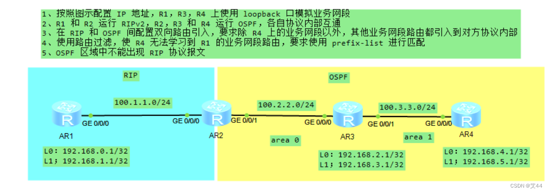
实验需求
1.按照图示配置 IP 地址,R1,R3,R4 上使用 loopback 口模拟业务网段
2.R1 和 R2 运行 RIPv2,R2,R3 和 R4 运行 OSPF,各自协议内部互通
3.在 RIP 和 OSPF 间配置双向路由引入,要求除 R4 上的业务网段以外,其他业务网段路由都引入到对方协议内部
4.使用路由过滤,使 R4 无法学习到 R1 的业务网段路由,要求使用 prefix-list 进行匹配
5.OSPF 区域中不能出现 RIP协议报文
实验思路与步骤
1.根据拓扑图进行ip配置
r1
[r1]int g0/0/0
[r1-GigabitEthernet0/0/0]ip a 100.1.1.1 24
[r1-GigabitEthernet0/0/0]int l0
[r1-LoopBack0]ip a 192.168.0.1 32
[r1-LoopBack0]int l1
[r1-LoopBack1]ip a 192.168.1.1 32
[r1-LoopBack1]q
[r1]dis ip in br
*down: administratively down
^down: standby
(l): loopback
(s): spoofing
The number of interface that is UP in Physical is 4
The number of interface that is DOWN in Physical is 2
The number of interface that is UP in Protocol is 4
The number of interface that is DOWN in Protocol is 2

Interface                         IP Address/Mask      Physical   Protocol
GigabitEthernet0/0/0              100.1.1.1/24         up         up
GigabitEthernet0/0/1              unassigned           down       down
GigabitEthernet0/0/2              unassigned           down       down
LoopBack0                         192.168.0.1/32       up         up(s)
LoopBack1                         192.168.1.1/32       up         up(s)
NULL0                             unassigned           up         up(s)
r2
[r2]int g 0/0/0
[r2-GigabitEthernet0/0/0]ip a 100.1.1.2 24
[r2-GigabitEthernet0/0/0]int g 0/0/1
[r2-GigabitEthernet0/0/1]ip a 100.2.2.2 24
[r2-GigabitEthernet0/0/1]q
[r2]dis ip in br
*down: administratively down
^down: standby
(l): loopback
(s): spoofing
The number of interface that is UP in Physical is 3
The number of interface that is DOWN in Physical is 1
The number of interface that is UP in Protocol is 3
The number of interface that is DOWN in Protocol is 1

Interface                         IP Address/Mask      Physical   Protocol
GigabitEthernet0/0/0              100.1.1.2/24         up         up
GigabitEthernet0/0/1              100.2.2.2/24         up         up
GigabitEthernet0/0/2              unassigned           down       down
NULL0                             unassigned           up         up(s)
r3
[r3]int g0/0/0
[r3-GigabitEthernet0/0/0]ip a 100.2.2.3 24
[r3-GigabitEthernet0/0/0]int g0/0/1
[r3-GigabitEthernet0/0/1]ip a 100.3.3.3 24
[r3-GigabitEthernet0/0/1]int l0
[r3-LoopBack0]ip a 192.168.2.1 32
[r3-LoopBack0]int l1
[r3-LoopBack1]ip a 192.168.3.1 32
[r3-LoopBack1]q
[r3]dis ip in br
*down: administratively down
^down: standby
(l): loopback
(s): spoofing
The number of interface that is UP in Physical is 5
The number of interface that is DOWN in Physical is 1
The number of interface that is UP in Protocol is 5
The number of interface that is DOWN in Protocol is 1

Interface                         IP Address/Mask      Physical   Protocol
GigabitEthernet0/0/0              100.2.2.3/24         up         up
GigabitEthernet0/0/1              100.3.3.3/24         up         up
GigabitEthernet0/0/2              unassigned           down       down
LoopBack0                         192.168.2.1/32       up         up(s)
LoopBack1                         192.168.3.1/32       up         up(s)
NULL0                             unassigned           up         up(s)
r4
[r4]int g0/0/0
[r4-GigabitEthernet0/0/0]ip a 100.3.3.4 24
[r4-GigabitEthernet0/0/0]int l0
[r4-LoopBack0]ip a 192.168.4.1 32
[r4-LoopBack0]int l1
[r4-LoopBack1]ip a 192.168.5.1 32
[r4-LoopBack1]q
[r4]dis ip in br
*down: administratively down
^down: standby
(l): loopback
(s): spoofing
The number of interface that is UP in Physical is 4
The number of interface that is DOWN in Physical is 2
The number of interface that is UP in Protocol is 4
The number of interface that is DOWN in Protocol is 2

Interface                         IP Address/Mask      Physical   Protocol
GigabitEthernet0/0/0              100.3.3.4/24         up         up
GigabitEthernet0/0/1              unassigned           down       down
GigabitEthernet0/0/2              unassigned           down       down
LoopBack0                         192.168.4.1/32       up         up(s)
LoopBack1                         192.168.5.1/32       up         up(s)
NULL0                             unassigned           up         up(s)
2.配置RIP和OSPF
RIP
r1
[r1]rip 1
[r1-rip-1]v 2
[r1-rip-1]un
[r1-rip-1]undo su
[r1-rip-1]undo summary
[r1-rip-1]ne 100.0.0.0
[r1-rip-1]ne 192.168.0.0
[r1-rip-1]ne 192.168.1.0
r2
[r2]rip 1
[r2-rip-1]v 2
[r2-rip-1]und
[r2-rip-1]undo su
[r2-rip-1]undo summary
[r2-rip-1]ne 100.0.0.0
[r2-rip-1]q
OSPF
r2
[r2]ospf 1 ro
[r2]ospf 1 router-id 1.1.1.1
[r2-ospf-1]a 0
[r2-ospf-1-area-0.0.0.0]ne 100.2.2.0 0.0.0.255
[r2-ospf-1-area-0.0.0.0]q
r3
[r3]ospf 1 r
[r3]ospf 1 router-id 2.2.2.2
[r3-ospf-1]a 0
[r3-ospf-1-area-0.0.0.0]ne 100.2.2.0 0.0.0.255
[r3-ospf-1-area-0.0.0.0]ne 192.168.2.1 0.0.0.0
[r3-ospf-1-area-0.0.0.0]ne 192.168.3.1 0.0.0.0
[r3-ospf-1-area-0.0.0.0]q
[r3-ospf-1]a 1
[r3-ospf-1-area-0.0.0.1]ne 100.3.3.0 0.0.0.255
[r3-ospf-1-area-0.0.0.1]q
r4
[r4]ospf 1 r
[r4]ospf 1 router-id 4.4.4.4
[r4-ospf-1]a 1
[r4-ospf-1-area-0.0.0.1]ne 100.3.3.0 0.0.0.255
[r4-ospf-1-area-0.0.0.1]ne 192.168.4.1 0.0.0.0
[r4-ospf-1-area-0.0.0.1]ne 192.168.5.1 0.0.0.0
[r4-ospf-1-area-0.0.0.1]q
3.在 RIP 和 OSPF 间配置双向路由引入,要求除 R4上的业务网段以外,其他业务网段路由都引入到对方协议内部
步骤1:rip和ospf间双向引入
[r2-rip-1]import-route ospf
[r2-rip-1]q
[r2]ospf 1
[r2-ospf-1]i
[r2-ospf-1]import-route rip
步骤2:创建acl来匹配 R4 上的业务网段路由,并把其他网段路由过滤掉
[r2]acl 2000
[r2-acl-basic-2000]rule deny source 192.168.4.0 0.0.1.255
[r2-acl-basic-2000]rule permit source 0.0.0.0 255.255.255.255
[r2-acl-basic-2000]q
步骤3:在r2上创建路由策略,关联ACL
[r2]route-policy aa permit node 10
[r2-route-policy]if-match acl 2000
步骤3:调用路由策略
[r2]rip 1
[r2-rip-1]im
[r2-rip-1]import-route os
[r2-rip-1]import-route ospf r
[r2-rip-1]import-route ospf route-policy aa
[r2-rip-1]q
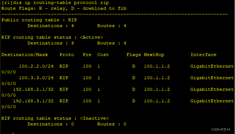
此时r1路由表
4.使用路由过滤,使 R4 无法学习到 R1 的业务网段路由,要求使用 prefix-list 进行匹配
r4
[r4]ip ip-prefix bb index 10 deny 192.168.0.0 23 less-equal 32
[r4]ip ip-prefix bb index 20 permit 0.0.0.0 0 less-equal 32
[r4]ospf 1
[r4-ospf-1]filter-policy ip-prefix bb import
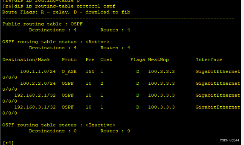
此时r4路有表
5.OSPF 区域中不能出现 RIP协议报文
在r2 的rip中配置静默接口
[r2]rip 1
[r2-rip-1]s
[r2-rip-1]silent-interface g0/0/1
至此,实验结束


 256
256

 被折叠的 条评论
为什么被折叠?
被折叠的 条评论
为什么被折叠?
 到【灌水乐园】发言


