


 本文深入探讨了TMS320F280049C DSP的CPU Timer和中断机制,介绍了硬件不支持中断嵌套的特性,通过软件方法实现中断,并详细解析了三个Timer的区别及中断信号传输方式。同时,提供了TI官方的配置例程和寄存器版例程,展示了如何配置定时器并触发中断。
继续280049C的学习,本节讨论CPU和中断。
timer
本DSP在硬件上是不支持中断嵌套的,仅可以通过一些软件的方法实现,具体方法可以参考[4],不过个人感觉没什么必要……
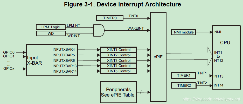
手册[1]对于CPU timer这一部分的介绍着实是有点简单,详细可以参考[3]中的介绍。TIMER2是给实时操作系统预留的,不过用户也可以使用。3个timer之间的区别是中断信号的传输不同,如下图所示,timer0需要经过PIE。
中断
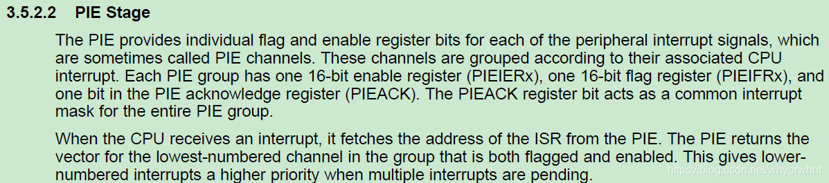
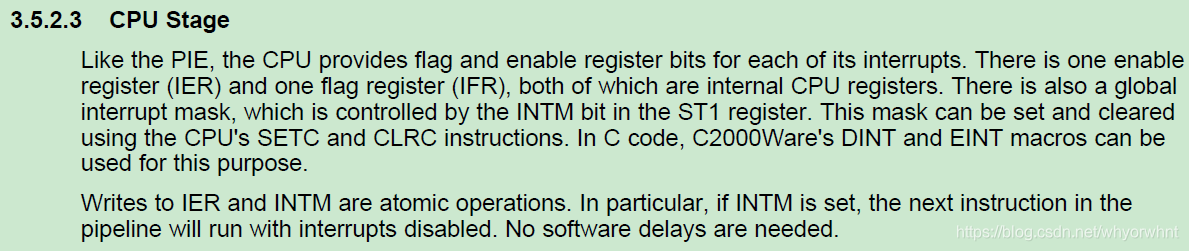
关于中断机制的介绍,也可以参考[3]入门,之后看手册的3.5节。
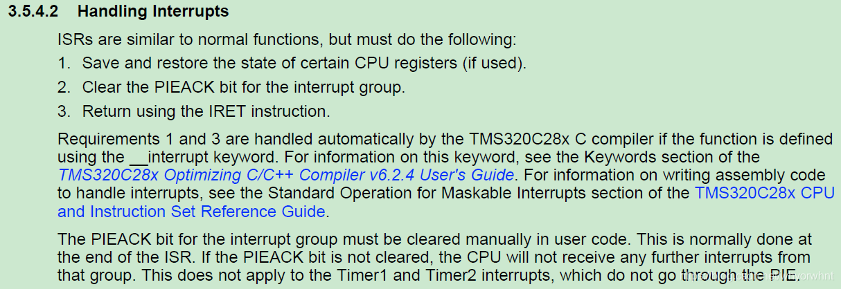
手册中有提到,中断时当前状态的进出栈是编译器自动的,我之前还奇怪怎么没人写进出栈的代码……
timer 例程
关于定时器,TI官方提供了2个配置例程。库函数版在C:\ti\c2000\C2000Ware_2_01_00_00\driverlib\f28004x\examples\timer
寄存器版在C:\ti\c2000\C2000Ware_2_01_00_00\device_support\f28004x\examples\timer
两个例程实现的功能一致,都是配置了定时器并触发中断。
手册中列出了用到的寄存器
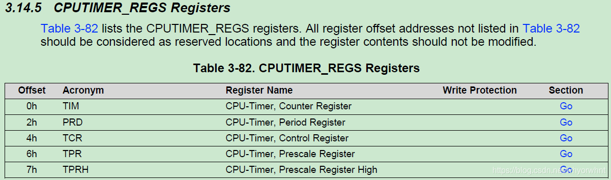
具体含义可参考手册和[2]中的介绍。
#include "F28x_Project.h"
#include "device.h"
#include "math.h"

#define DEVICE_GPIO_PIN_LED1        23U  // GPIO number for LD4
#define DEVICE_GPIO_PIN_LED2        34U  // GPIO number for LD5


// 计时器中断服务程序ISR
__interrupt void cpuTimer0ISR(void);
__interrupt void cpuTimer1ISR(void);
__interrupt void cpuTimer2ISR(void);


void main(void)
{
    // 初始化时钟和外设 Initialize device clock and peripherals
    Device_init();
    // InitSysCtrl();  //本工程不能使用寄存器的InitSysCtrl();函数初始化。

    InitGpio();  //寄存器指令配置,初始化GPIO并设置为推挽输出
    GPIO_SetupPinMux(DEVICE_GPIO_PIN_LED1, GPIO_MUX_CPU1, 0);
    GPIO_SetupPinOptions(DEVICE_GPIO_PIN_LED1, GPIO_OUTPUT, GPIO_PUSHPULL);
    GPIO_SetupPinMux(DEVICE_GPIO_PIN_LED2, GPIO_MUX_CPU1, 0);
    GPIO_SetupPinOptions(DEVICE_GPIO_PIN_LED2, GPIO_OUTPUT, GPIO_PUSHPULL);

    // 初始化PIE并清空PIE寄存器,关闭CPU中断
    // Initialize PIE and clear PIE registers. Disables CPU interrupts.
    Interrupt_initModule();

    // 初始化PIE向量表
    // Initialize the PIE vector table with pointers to the shell Interrupt  // Service Routines (ISR).
    Interrupt_initVectorTable();

    // 初始化外设,这里只初始化计时器
    // Initialize the Device Peripheral. For this example, only initialize the Cpu Timers.
    InitCpuTimers();

    // 映射中断服务程序 Map ISR functions
    EALLOW;
    PieVectTable.TIMER0_INT = &cpuTimer0ISR;
    PieVectTable.TIMER1_INT = &cpuTimer1ISR;
    PieVectTable.TIMER2_INT = &cpuTimer2ISR;
    EDIS;

    // 设置计时器周期
    // 100MHz CPU 频率, 1 second 周期 (in uSeconds)
    ConfigCpuTimer(&CpuTimer0, 100, 1000000);
    ConfigCpuTimer(&CpuTimer1, 100, 600000);
    ConfigCpuTimer(&CpuTimer2, 100, 1000000);

    // 计时器的控制寄存器 TIE位置1,允许其向CPU请求中断
    CpuTimer0Regs.TCR.all = 0x4000;
    CpuTimer1Regs.TCR.all = 0x4000;
    CpuTimer2Regs.TCR.all = 0x4000;

    // Enables CPU int1, int13, and int14 which are connected to CPU-Timer 0,
    // CPU-Timer 1, and CPU-Timer 2 respectively.
    // Enable TINT0 in the PIE: Group 1 interrupt 7
    Interrupt_enable(INT_TIMER0);
    Interrupt_enable(INT_TIMER1);
    Interrupt_enable(INT_TIMER2);
    /*
    IER |= M_INT1;
    IER |= M_INT13;
    IER |= M_INT14;
    // Enable TINT0 in the PIE: Group 1 interrupt 7
    PieCtrlRegs.PIEIER1.bit.INTx7 = 1; */

    // Enable Global Interrupt (INTM) and realtime interrupt (DBGM)
    EINT;
    ERTM;

    float a=cos((float)3.1415926/4);  // FPU32
    float b=__sin((float)(3.14/4));   // TMU

    for(;;)
    {
        // Turn on LED
        // 硬件电路设计是GPIO输出低电平时LED亮
        GPIO_writePin(DEVICE_GPIO_PIN_LED1, 0);

        // 延迟0.5s Delay for a bit.
        DEVICE_DELAY_US(500000);

        // Turn off LED
        GPIO_writePin(DEVICE_GPIO_PIN_LED1, 1);

        // Delay for a bit.
        DEVICE_DELAY_US(500000);
    }
}

// cpuTimer0ISR - CPU Timer0 ISR with interrupt counter
__interrupt void cpuTimer0ISR(void)
{
    CpuTimer0.InterruptCount++;

    GPIO_togglePin(DEVICE_GPIO_PIN_LED1);

    // Acknowledge this interrupt to receive more interrupts from group 1
        // Interrupt_clearACKGroup(INTERRUPT_ACK_GROUP1);
    PieCtrlRegs.PIEACK.all = PIEACK_GROUP1;
}

// cpuTimer1ISR - CPU Timer1 ISR with interrupt counter
__interrupt void cpuTimer1ISR(void)
{
    GPIO_togglePin(DEVICE_GPIO_PIN_LED2);

    // The CPU acknowledges the interrupt
    CpuTimer1.InterruptCount++;
}

// cpuTimer2ISR CPU Timer2 ISR with interrupt counter
__interrupt void cpuTimer2ISR(void)
{
    // The CPU acknowledges the interrupt
    CpuTimer2.InterruptCount++;
}


 1266
1266

 被折叠的 条评论
为什么被折叠?
被折叠的 条评论
为什么被折叠?
 到【灌水乐园】发言


