


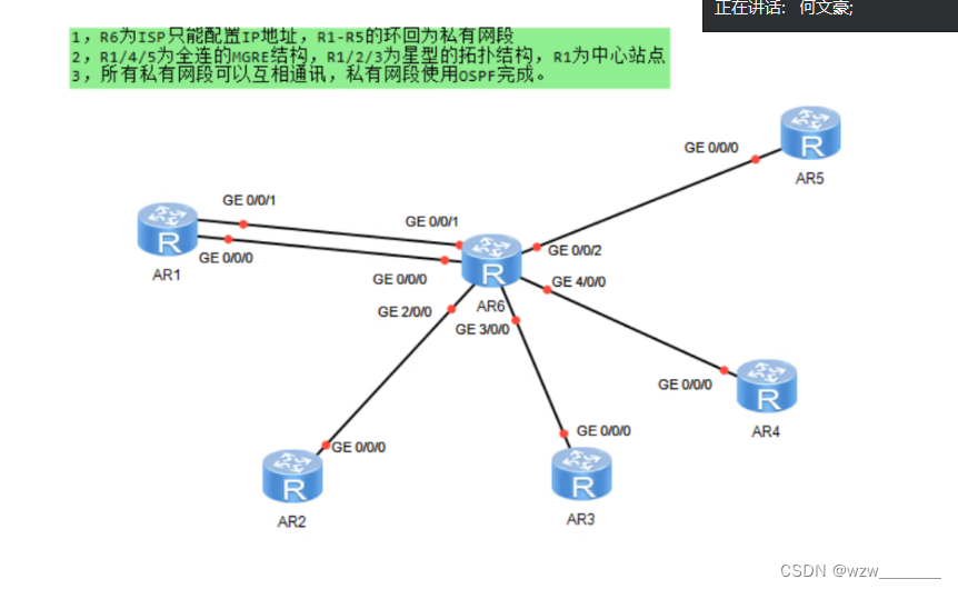
拓扑图
分析题目
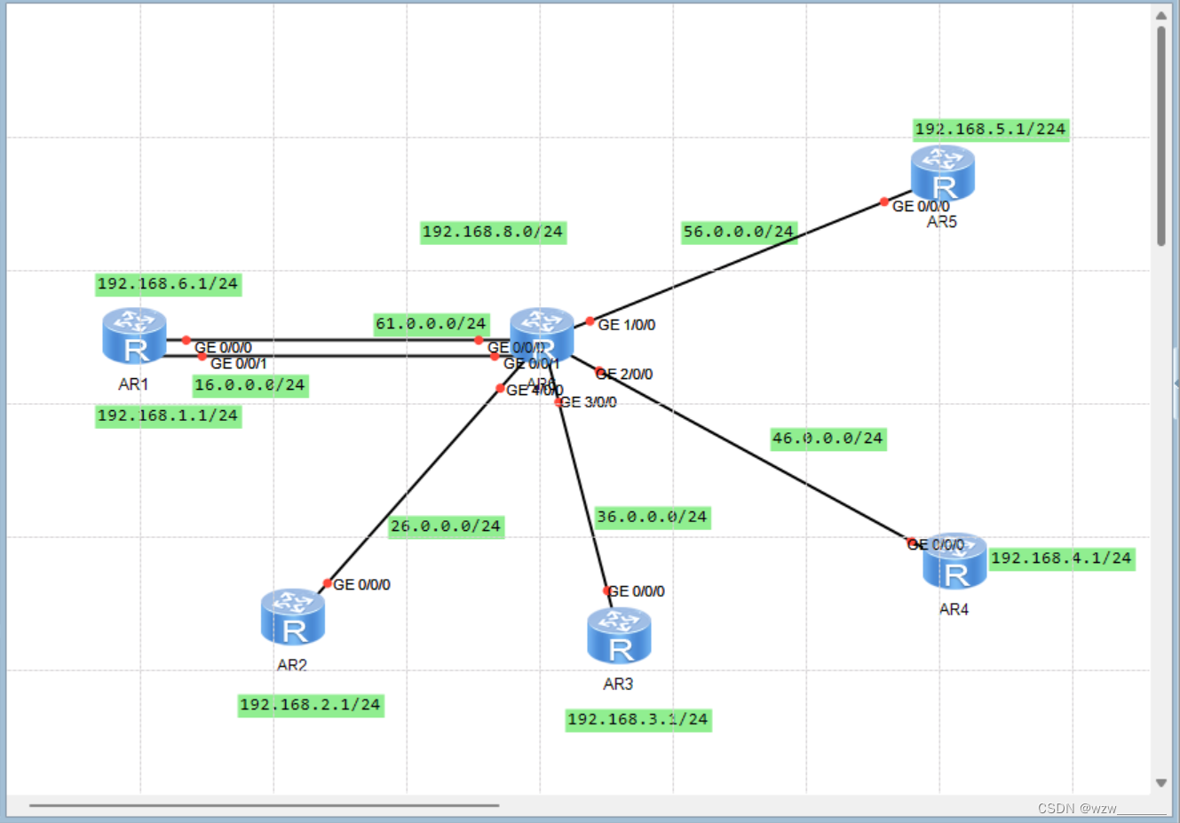
1.首先给各个设备分配IP并设置缺省使全网可达
2.进入各个点接口进行配置相应的拓扑或MGRE
3.因为MGRE不支持组播,所以使用OSPF
一.实验配置
R1为中心
R1拓扑结构,MGRE结构
[r1]int Tunnel 0/0/0
[r1-Tunnel0/0/0]ip add 192.168.7.1 24
[r1-Tunnel0/0/0]tunnel-protocol gre p2mp
[r1-Tunnel0/0/0]source 16.0.0.1
April 14 2024 15:35:45-08:00 r1 %%01IFNET/4/LINK_STATE(l)[0]:The line protocol IP
on the interface Tunnel0/0/0 has entered the UP state.
[r1-Tunnel0/0/0]nhrp network-id 100
[r1]int t0/0/1
[r1-Tunnel0/0/1]ip add 192.168.8.1 24
[r1-Tunnel0/0/1]tunnel-protocol gre p2mp
[r1-Tunnel0/0/1]source 61.0.0.1
April 14 2024 15:45:23-08:00 r1 %%01IFNET/4/LINK_STATE(l)[0]:The line protocol IP
on the interface Tunnel0/0/1 has entered the UP state.
[r1-Tunnel0/0/1]nhrp network-id 200
R2拓扑结构
[r2]int t0/0/0
[r2-Tunnel0/0/0]ip add 192.168.7.2 24
[r2-Tunnel0/0/0]tunnel-protocol gre p2mp
[r2-Tunnel0/0/0]source GigabitEthernet 0/0/0
April 14 2024 18:44:47-08:00 r2 %%01IFNET/4/LINK_STATE(l)[0]:The line protocol IP
on the interface Tunnel0/0/0 has entered the UP state.
[r2-Tunnel0/0/0]nhrp network-id 100
[r2-Tunnel0/0/0]nhrp entry 192.168.7.1 16.0.0.1 register
R3拓扑结构
[r3]int t0/0/0
[r3-Tunnel0/0/0]ip add 192.168.7.3 24
[r3-Tunnel0/0/0]tunnel-protocol gre p2mp
[r3-Tunnel0/0/0]source GigabitEthernet 0/0/0
April 14 2024 18:46:16-08:00 r3 %%01IFNET/4/LINK_STATE(l)[0]:The line protocol IP
on the interface Tunnel0/0/0 has entered the UP state.
[r3-Tunnel0/0/0]nhrp network-id 100
[r3-Tunnel0/0/0]nhrp entry 192.168.7.1 16.0.0.1 register
R4MGRE结构
[r4]int t0/0/1
[r4-Tunnel0/0/1]ip add 192.168.8.2 24
[r4-Tunnel0/0/1]tunnel-protocol gre p2mp
[r4-Tunnel0/0/1]source g0/0/0
April 14 2024 19:02:34-08:00 r4 %%01IFNET/4/LINK_STATE(l)[0]:The line protocol IP
on the interface Tunnel0/0/1 has entered the UP state.
[r4-Tunnel0/0/1]nhrp network-id 200
[r4-Tunnel0/0/1]nhrp entry 192.168.8.1 61.0.0.1 register
R5MGRE结构
[r5]int t0/0/1
[r5-Tunnel0/0/1]ip add 192.168.8.3 24
[r5-Tunnel0/0/1]tunnel-protocol gre p2mp
[r5-Tunnel0/0/1]source g0/0/0
April 14 2024 19:03:48-08:00 r5 %%01IFNET/4/LINK_STATE(l)[0]:The line protocol IP
on the interface Tunnel0/0/1 has entered the UP state.
[r5-Tunnel0/0/1]nhrp network-id 200
[r5-Tunnel0/0/1]nhrp entry 192.168.8.1 61.0.0.1 register
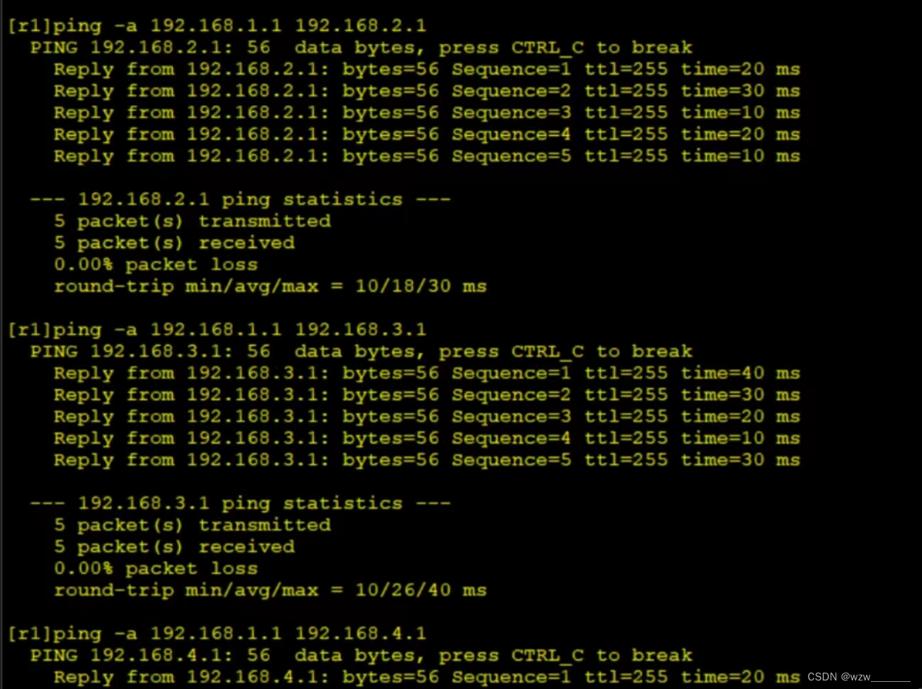
二.私有网段可以相互通信(使用OSPF)
[r1-Tunnel0/0/0]nhrp entry multicast dynamic
开启R1-R5的OSPF
[r1]ospf network-type broadcast
[r2]ospf network-type broadcast
[r3]ospf network-type broadcast
[r4]ospf network-type broadcast
[r5]ospf network-type broadcast
三.实验结果


 335
335

 被折叠的 条评论
为什么被折叠?
被折叠的 条评论
为什么被折叠?
 到【灌水乐园】发言


