


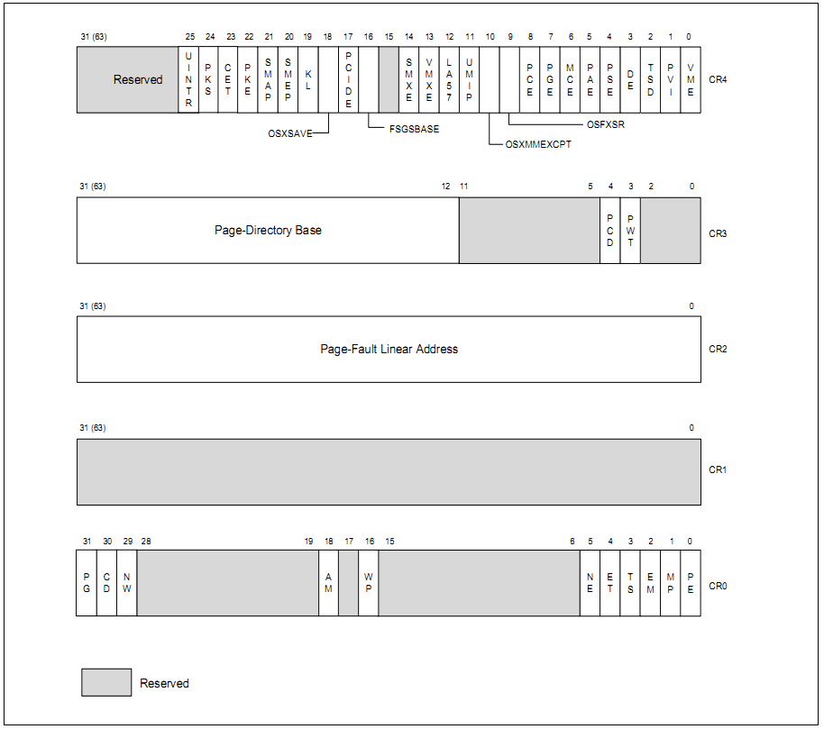
CR0 — Contains system control flags that control operating mode and states of the processor.
CR1 — Reserved.
CR2 — Contains the page-fault linear address (the linear address that caused a page fault).
CR3 — Contains the physical address of the base of the paging-structure hierarchy and two flags (PCD and PWT). Only the most-significant bits (less the lower 12 bits) of the base address are specified; the lower 12 bits of the address are assumed to be 0. The first paging structure must thus be aligned to a page (4-KByte) boundary. The PCD and PWT flags control caching of that paging structure in the processor’s internal data caches (they do not control TLB caching of page-directory information).
When using the physical address extension, the CR3 register contains the base address of the page-directory-pointer table. With 4-level paging and 5-level paging, the CR3 register contains the base address of the PML4 table and PML5 table, respectively.
CR4 — Contains a group of flags that enable several architectural extensions, and indicate operating system or executive support for specific processor capabilities. Bits CR4[63:32] can only be used for IA-32e mode only features that are enabled after entering 64-bit mode. Bits CR4[63:32] do not have any effect outside of IA-32e mode.
CR8 — Provides read and write access to the Task Priority Register (TPR). It specifies the priority threshold value that operating systems use to control the priority class of external interrupts allowed to interrupt the processor. This register is available only in 64-bit mode. However, interrupt filtering continues to apply in compatibility mode.
所有页表的物理地址被页目录表项指向了,那么页目录的物理地址,处理器是怎么知道的呢?
告诉 CR3 寄存器,也叫做: PDBR(Page Table Base Register)。


 被折叠的 条评论
为什么被折叠?
被折叠的 条评论
为什么被折叠?
 到【灌水乐园】发言


