


继续前行...
在设备描述表中还有一个路径层,如字面意思,即是在地域上画上了界限,别人无法侵犯;
在MFC中,创建路径层利用CDC类提供的BeginPath和EndPath这两个函数来实现的,首先调用BeginPath,是在设备描述表中打开一个路径层,然后利用图形设备接口(GDI)提供的绘图函数进行绘图操作,最后通过EndPath函数关闭路径层。
下面即是在路径层绘制一个矩形Rectangle,
BOOL Rectangle( int x1, inty1, intx2, inty2 );
左上角我们知道,可是获得右下角的坐标的话,得使用GetTextExtent函数,用来获得特定字符串在窗口显示时所占的宽度和高度;
CSize GetTextExtent( const CString&str ) const;
贴下:
CSize sz=pDC->GetTextExtent(str);

pDC->BeginPath();
pDC->Rectangle(50,50,50+sz.cx,50+sz.cy);
pDC->EndPath();
其中CSize sz=pDC->GetTextExtent(str);是对字符串str操作,即返回值都是str的一些属性,切记...
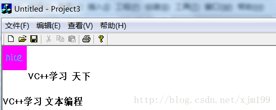
发现与之前的没变化,将BeginPath()和EndPath()注释;
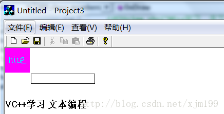
这是因为设备描述表默认一个白色画刷,当绘制矩形时,会用画刷填充矩形内部,所以会将之前的文字覆盖了;
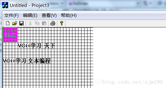
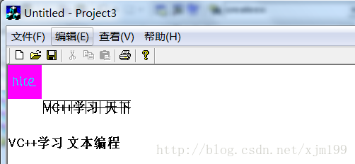
加上BeginPath()和EndPath()我们可能感觉没什么用,这时,我们先加入网格状线条:
for(int i=0;i<300;i+=10)
{
	pDC->MoveTo(0,i);
	pDC->LineTo(300,i);
	pDC->MoveTo(i,0);
	pDC->LineTo(i,300);
}
执行一下:
在CDC类中有一个SelectClipPath函数,它是把当前设置的路径层和设备描述表中已有的裁剪区按照一种特定的模式进行一个互操作。
BOOL SelectClipPath( int nMode);
其中nMode用来指定互操作的模式;
Specifies the way to use the path. The following values are allowed:
- RGN_AND The new clipping region includes the intersection (overlapping areas) of the current clipping region and the current path.
- RGN_COPY The new clipping region is the current path.
- RGN_DIFF The new clipping region includes the areas of the current clipping region, and those of the current path are excluded.
- RGN_OR The new clipping region includes the union (combined areas) of the current clipping region and the current path.
- RGN_XOR The new clipping region includes the union of the current clipping region and the current path, but without the overlapping areas.
我们可以试一下这几个值:
pDC->SelectClipPath(RGN_DIFF);
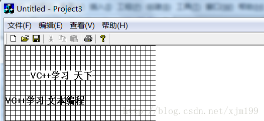
pDC->SelectClipPath(RGN_AND);
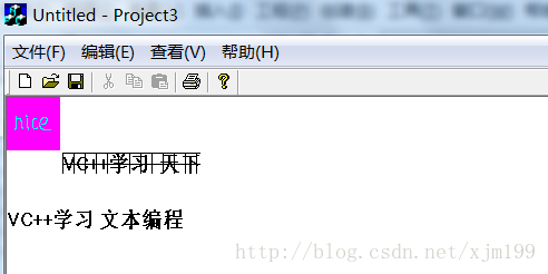
pDC->SelectClipPath(RGN_COPY);
剩下的大家可以自己试试...
小工程可见:http://download.csdn.net/detail/xjm199/6782459
继续加油...o(∩_∩)o


 12万+
12万+

 被折叠的 条评论
为什么被折叠?
被折叠的 条评论
为什么被折叠?
 到【灌水乐园】发言


