


 本文详细介绍了MSP430微控制器中USI模块的SPI模式配置与使用方法。主要内容包括SPI模式的硬件框架与时序图解析,关键寄存器配置说明,以及具体的SPI读写操作实现代码。
简述
在 MSP430 系列中微控制器中有三种串行通讯模块。它们分别是 USART 、 USI 和 USCI 。
USART 支持同一硬件模块的两种串行模式,分别是 UART 和 SPI 。 USART 实现了独立的收发转换暂存器和 分离的收发缓冲暂存器以及中断能力。
通用同步串行通讯 (USI) ,对于一个 GPIO 数量少的设备来说,是一个高性能串行接口。它是一个 8 或 16bit 移位寄存器,可被用作输出数据,或配合软件一起使用时,可以实现串行通讯。而且 USI 包含了一个能轻松实现 SPI 和 I2C 通讯的硬件功能。 USI 模块还包含了中断功能来减少必要 的对串行通讯管理软件并保持 MSP430 超低功耗的能力。
通用串行接口 (USCI) 是 MSP430 串行接口的新标准,支持使用单个硬件模块实现多种串行通讯模 式。 USCI 支持所有异步通讯模式和一个 SPI 。异步模式包括了 UART , IrDA 和 LIN 。 IrDA 和 LIN 只提供了其物理层的支持。有两个独立模块 USCI_A 和 USCI_B 可以同时工作。所有模块能够从 任何 LPMx 模式中唤醒。而且, USCI 有中断驱动和 DMA 功能。
msp430g2xx3的有usci。其他的是usi。USI中包括SPI模式和I2C模式。本篇主要讲一讲SPI模式。
SPI模式详解
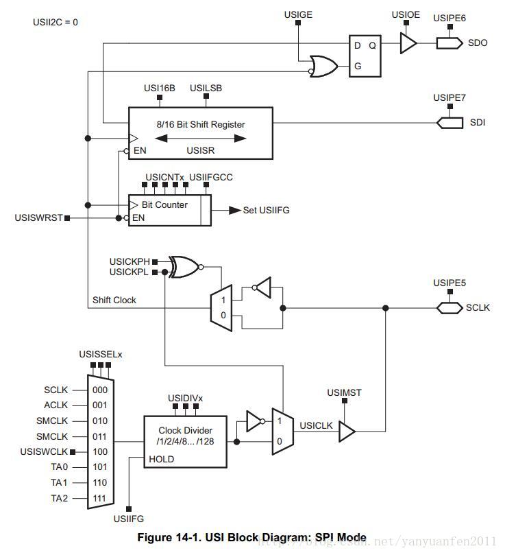
先看用户开发手册里的SPI硬件框架图:
再看SPI里的时序图:
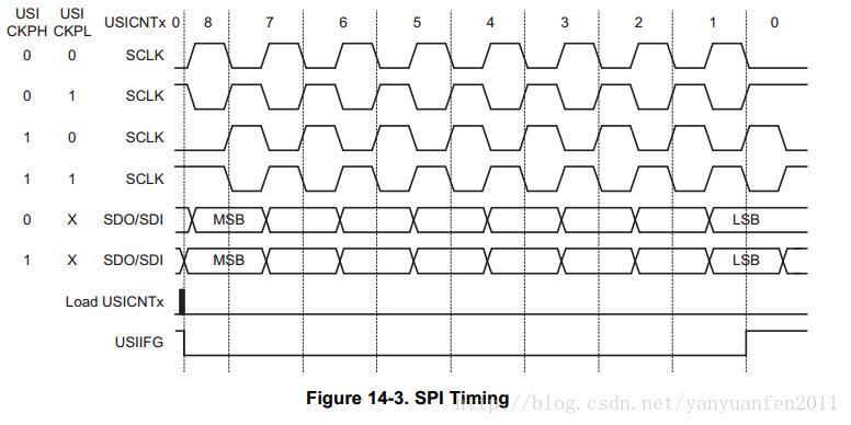
主要配置在于: 主从配置,相位配置及大小端配置。这三个配置对了,通讯才能正常。
下面主要看寄存器的相关位的设置:
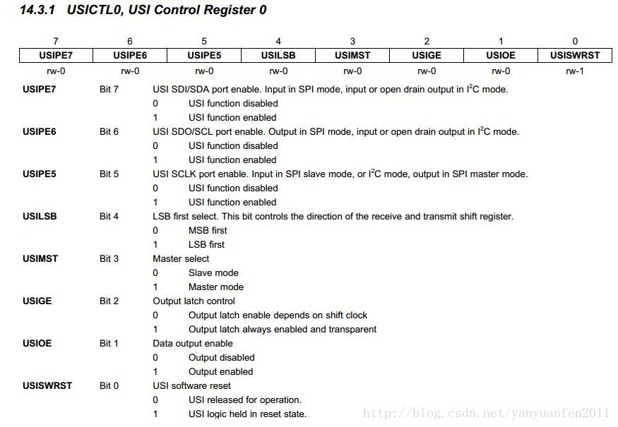
USICTL0主要是配置三个PIN,P1.5, P1.6, P1.7。还有MSB还是LSB。主模式还是从模式。
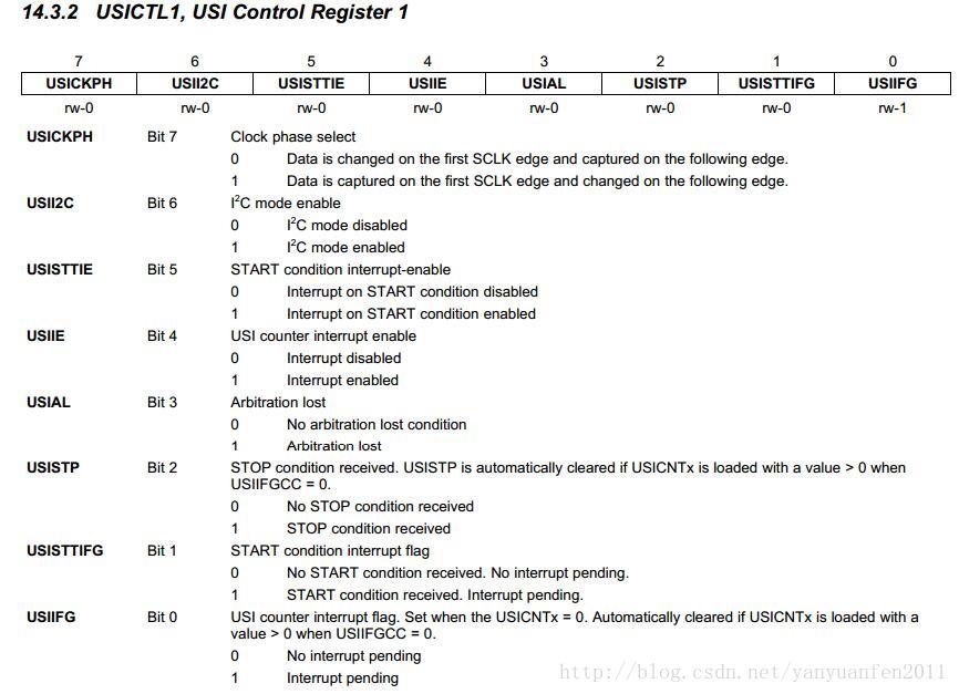
USICTL1主要是配置关于I2C模式。SPI相位,是时钟上升沿来数据还是下降沿来数据。
USICNT主要是配置SPI的时钟。
源代码
这是我自已用的代码,如果要引用的话,需要根据自已的实际情况作相应的更改。
void Init_SPI(void)
{
Init_CSN();
Init_IRQ();
/* USICTL0:
USIPE7: USI SDI/SDA port enable;
USIPE6: USI SDI/SDA port enable;
USIPE5: USI SDI/SDA port enable;
USILSB: LSB first select.
This bit controls the direction of the receive and transmit shift register.
USIMST: Master select;
USIGE : Output latch control;
USIOE : Data output enable;
USISWRST : USI software reset.
*/
USICTL0 |= USIPE7 + USIPE6 + USIPE5 + USIMST + USIOE; // Port, SPI master
/* USICTL1:
USICKPH: Clock phase select
USII2C : I2C mode enable
USISTTIE : START condition interrupt-enable
USIIE : USI counter interrupt enable
USIAL : Arbitration lost
USISTP : STOP condition received.
USISTP is automatically cleared if USICNTx is loaded with a value > 0 when USIIFGCC = 0.
USISTTIFG : START condition interrupt flag
USIIFG : USI counter interrupt flag. Set when the USICNTx = 0.
Automatically cleared if USICNTx is loaded with a value > 0 when USIIFGCC = 0.
*/
//USICTL1 |= USIIE;
USICTL1 |= USICKPH;//SDO in SCK rising edge.
USICNT |= USI16B; //use 16 bit register
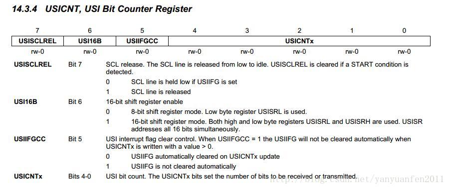
/* USICNT:
USISCLREL: SCL release.
The SCL line is released from low to idle. USISCLREL is cleared if a START condition is detected.
USI16B : 16-bit shift register enable
USIIFGCC : USI interrupt flag clear control. When USIIFGCC = 1 the USIIFG will not be cleared automatically when
USICNTx is written with a value > 0.
USICNTx :USI bit count. The USICNTx bits set the number of bits to be received or transmitted.
*/
/*
USISRL:
USISRLx : Contents of the USI low byte shift register
USISRH:
USISRHx : Contents of the USI high byte shift register. Ignored when USI16B = 0.
*/
/* USICKCTL:
USIDIVx : Clock divider select
USISSELx : Clock source select. Not used in slave mode.
USICKPL : Clock polarity select
USISWCLK : Software clock
*/
//Divider by 0, Clock source select SMCLK.
USICKCTL = USIDIV_0 + USISSEL_2;
// USI released for operation
USICTL0 &= ~USISWRST;
}
/*******************************************/
// SPI Write 8 bit data
// Byte: the byte want to write
/*******************************************/
unsigned char SPI_8Base(unsigned char byte)
{
USISRL = byte;
USICNT = 0x08;// re-load counter
while (0 == (USIIFG & USICTL1)); // Counter clear?
return(USISRL);
}
/*******************************************/
// SPI Write 16 bit data
// address: the address of want to write
// data: the byte want to write
/*******************************************/
unsigned char SPI_16Base(unsigned char address, unsigned char data)
{
USISRH = address;
USISRL = data;
USICNT |= 0x10;//16 bit re-load counter
while (0 == (USIIFG & USICTL1)); // Counter clear?
return(USISRL);
}
unsigned char SPI_write_read(unsigned char address)
{
/*
When USIIFG = 0 and USICNTx > 0, clock generation is enabled and the master will begin clocking in/out
data using USISR.
Received data must be read from the shift register before new data is written into it for transmission. In a
typical application, the USI software will read received data from USISR, write new data to be transmitted
to USISR, and enable the module for the next transfer by writing the number of bits to be transferred to
USICNTx
*/
address |= 0x80;
USISRH = address;
USISRL = 0x00;
Clr_CSN();
USICNT |= 0x10;//16 bit re-load counter
while (0 == (USIIFG & USICTL1)); // Counter clear?
Set_CSN();
return USISRL;
}
/*******************************************/
// SPI Write byte
// addr: the address of want to write
// *dataByte: the byte want to write
/*******************************************/
void SPI_write(unsigned char address, unsigned char data)
{
address &= ~0x80;
USISRH = address;
USISRL = data;
Clr_CSN();
USICNT |= 0x10;//16 bit re-load counter
while (0 == (USIIFG & USICTL1)); // Counter clear?
Set_CSN();
}
/*******************************************/
// SPI Read byte
// addr: the address of want to read
// *spi_data: the byte whick get will saved
/*******************************************/
void SPI_read(unsigned char address, unsigned char *data)
{
address |= 0x80;
USISRH = address;
USISRL = 0x00;
Clr_CSN();
USICNT |= 0x10;//16 bit re-load counter
while (0 == (USIIFG & USICTL1)); // Counter clear?
Set_CSN();
*data = USISRL;
}
/*******************************************/
// SPI Multi Read byte
// addr: the address of want to read
// *spi_data: the byte whick get will saved
// data_length: the length of data.
/*******************************************/
void SPI_multi_read (unsigned char address,
unsigned char* spi_data, unsigned char data_length)
{
unsigned char k = 0;
address |= 0x80;
USISRH = address;
Clr_CSN();
//Send address first.
USICNT |= 0x08;//8 bit re-load counter
while (0 == (USIIFG & USICTL1)); // Counter clear?
//Read multi data byte.
for(k = 0; k < data_length; k++)
{
USICNT |= 0x08;//8 bit re-load counter
while (0 == (USIIFG & USICTL1)); // Counter clear?
*(spi_data+k) = USISRL;
}
Set_CSN();
}引用
- MSP430G2xx1用户指南:http://download.csdn.net/detail/yanyuanfen2011/9893166


 5852
5852


 被折叠的 条评论
为什么被折叠?
被折叠的 条评论
为什么被折叠?
 到【灌水乐园】发言


