


SPI是"Serial Peripheral Interface" 的缩写,是一种四线制的同步串行通信接口,用来连接微控制器、传感器、存储设备,SPI设备分为主设备和从设备两种,用于通信和控制的四根线分别是:
- CS 片选信号
- SCK 时钟信号
- MISO 主设备的数据输入、从设备的数据输出脚
- MOSI 主设备的数据输出、从设备的数据输入脚
一、硬件结构
通常,负责发出时钟信号的设备我们称之为主设备,另一方则作为从设备,下图是一个SPI系统的硬件连接示例:

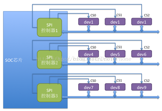
如上图所示,主设备对应SOC芯片中的SPI控制器,通常,一个SOC中可能存在多个SPI控制器,像上面的例子所示,SOC芯片中有3个SPI控制器。每个控制器下可以连接多个SPI从设备,每个从设备有各自独立的CS引脚。每个从设备共享另外3个信号引脚:SCK、MISO、MOSI。任何时刻,只有一个CS引脚处于有效状态,与该有效CS引脚连接的设备此时可以与主设备(SPI控制器)通信,其它的从设备处于等待状态,并且它们的3个引脚必须处于高阻状态。
二、工作时序
按照时钟信号和数据信号之间的相位关系,SPI有4种工作时序模式:
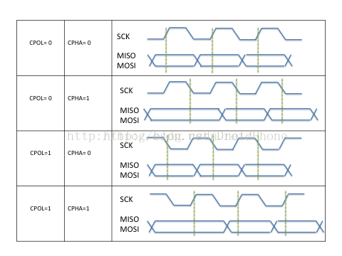
- CPOL=0,CPHA=1 模式0
- CPOL=0,CPHA=1 模式1
- CPOL=1,CPHA=0 模式2
- CPOL=1,CPHA=1 模式3
三、确定驱动文件
SPI作为linux里面比较小的一个子系统,其驱动程序位于/drivers/spi/*目录,首先,我们可以通过Makefile及Kconfig来确定我们需要看的源文件。
#
# Makefile for kernel SPI drivers.
#
# small core, mostly translating board-specific
# config declarations into driver model code
obj-$(CONFIG_SPI_MASTER)		+= spi.o
obj-$(CONFIG_SPI_SPIDEV)		+= spidev.o
# SPI master controller drivers (bus)
obj-$(CONFIG_SPI_BITBANG) += spi-bitbang.o
obj-$(CONFIG_SPI_IMX) += spi-imx.o
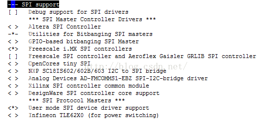
对应的Kconfig去配置内核
编译生成的目标文件如下
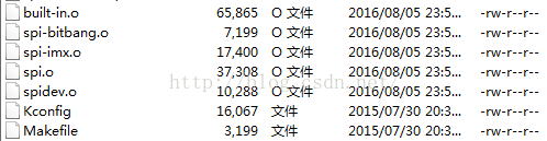
通过以上分析我们知道,spi驱动由三部分组成,分别是core(spi.c),master controller driver (spi_imx.c)以及SPIprotocol drivers (spidev.c)。
四、数据结构分析
Spi驱动涉及的数据结构主要位于/include/linux/spi.h,其中spi.c,spi-imx.c,spidev.c均用到了spi.h里的结构体。
1.spi_master
spi_master代表一个主机控制器,此处表示imx的SPI控制器。一般不需要自己编写spi控制器驱动,但是了解这个结构体还是必要的。
struct spi_master {
	struct device	dev;         //设备模型使用

	struct list_head list;

	/* other than negative (== assign one dynamically), bus_num is fully
	 * board-specific.  usually that simplifies to being SOC-specific.
	 * example:  one SOC has three SPI controllers, numbered 0..2,
	 * and one board's schematics might show it using SPI-2.  software
	 * would normally use bus_num=2 for that controller.
	 */
	s16			bus_num;   //总线(或控制器)编号,imx6q有5个spi控制器,0~4

	/* chipselects will be integral to many controllers; some others
	 * might use board-specific GPIOs.
	 */
	u16			num_chipselect;  //片选数量,决定该控制器下面挂接多少个SPI设备,从设备的片选号不能大于这个数量

	/* some SPI controllers pose alignment requirements on DMAable
	 * buffers; let protocol drivers know about these requirements.
	 */
	u16			dma_alignment;

	/* spi_device.mode flags understood by this controller driver */
	u16			mode_bits;            //master支持的设备模式

	/* bitmask of supported bits_per_word for transfers */
	u32			bits_per_word_mask;
#define SPI_BPW_MASK(bits) BIT((bits) - 1)
#define SPI_BIT_MASK(bits) (((bits) == 32) ? ~0U : (BIT(bits) - 1))
#define SPI_BPW_RANGE_MASK(min, max) (SPI_BIT_MASK(max) - SPI_BIT_MASK(min - 1))

	/* limits on transfer speed */
	u32			min_speed_hz;
	u32			max_speed_hz;

	/* other constraints relevant to this driver */
	u16			flags;
#define SPI_MASTER_HALF_DUPLEX	BIT(0)		/* can't do full duplex */
#define SPI_MASTER_NO_RX	BIT(1)		/* can't do buffer read */
#define SPI_MASTER_NO_TX	BIT(2)		/* can't do buffer write */
#define SPI_MASTER_MUST_RX      BIT(3)		/* requires rx */
#define SPI_MASTER_MUST_TX      BIT(4)		/* requires tx */

	/* lock and mutex for SPI bus locking */
	spinlock_t		bus_lock_spinlock;
	struct mutex		bus_lock_mutex;

	/* flag indicating that the SPI bus is locked for exclusive use */
	bool			bus_lock_flag;

	/* Setup mode and clock, etc (spi driver may call many times).
	 *
	 * IMPORTANT:  this may be called when transfers to another
	 * device are active.  DO NOT UPDATE SHARED REGISTERS in ways
	 * which could break those transfers.
	 */
	int			(*setup)(struct spi_device *spi);  //根据spi设备更新硬件配置。设置模式、时钟等,这个需要我们自己具体实现,主要设置SPI控制器和工作方式

	/* bidirectional bulk transfers
	 *
	 * + The transfer() method may not sleep; its main role is
	 *   just to add the message to the queue.
	 * + For now there's no remove-from-queue operation, or
	 *   any other request management
	 * + To a given spi_device, message queueing is pure fifo
	 *
	 * + The master's main job is to process its message queue,
	 *   selecting a chip then transferring data
	 * + If there are multiple spi_device children, the i/o queue
	 *   arbitration algorithm is unspecified (round robin, fifo,
	 *   priority, reservations, preemption, etc)
	 *
	 * + Chipselect stays active during the entire message
	 *   (unless modified by spi_transfer.cs_change != 0).
	 * + The message transfers use clock and SPI mode parameters
	 *   previously established by setup() for this device
	 */
	int			(*transfer)(struct spi_device *spi,
						struct spi_message *mesg);  //添加消息到队列的方法。这个函数不可睡眠。它的职责是安排发生的传送并且调用注册的回调函数complete()。这个不同的控制器要具体实现,传输数据最后都要调用这个函数

	/* called on release() to free memory provided by spi_master */
	void			(*cleanup)(struct spi_device *spi); //cleanup函数会在spidev_release函数中被调用,spidev_release被登记为spi dev的release函数。

	/*
	 * Used to enable core support for DMA handling, if can_dma()
	 * exists and returns true then the transfer will be mapped
	 * prior to transfer_one() being called.  The driver should
	 * not modify or store xfer and dma_tx and dma_rx must be set
	 * while the device is prepared.
	 */
	bool			(*can_dma)(struct spi_master *master,
					   struct spi_device *spi,
					   struct spi_transfer *xfer);

	/*
	 * These hooks are for drivers that want to use the generic
	 * master transfer queueing mechanism. If these are used, the
	 * transfer() function above must NOT be specified by the driver.
	 * Over time we expect SPI drivers to be phased over to this API.
	 */
	bool				queued;
	struct kthread_worker		kworker;
	struct task_struct		*kworker_task;
	struct kthread_work		pump_messages;
	spinlock_t			queue_lock;
	struct list_head		queue;
	struct spi_message		*cur_msg;
	bool				busy;
	bool				running;
	bool				rt;
	bool				auto_runtime_pm;
	bool                            cur_msg_prepared;
	bool				cur_msg_mapped;
	struct completion               xfer_completion;
	size_t				max_dma_len;

	int (*prepare_transfer_hardware)(struct spi_master *master);
	int (*transfer_one_message)(struct spi_master *master,
				    struct spi_message *mesg);
	int (*unprepare_transfer_hardware)(struct spi_master *master);
	int (*prepare_message)(struct spi_master *master,
			       struct spi_message *message);
	int (*unprepare_message)(struct spi_master *master,
				 struct spi_message *message);

	/*
	 * These hooks are for drivers that use a generic implementation
	 * of transfer_one_message() provied by the core.
	 */
	void (*set_cs)(struct spi_device *spi, bool enable);
	int (*transfer_one)(struct spi_master *master, struct spi_device *spi,
			    struct spi_transfer *transfer);

	/* gpio chip select */
	int			*cs_gpios;

	/* DMA channels for use with core dmaengine helpers */
	struct dma_chan		*dma_tx;
	struct dma_chan		*dma_rx;

	/* dummy data for full duplex devices */
	void			*dummy_rx;
	void			*dummy_tx;
};
2. spi_device
spi_device代表一个外围spi设备,由master controller driver注册完成后扫描BSP中注册设备产生的设备链表并向spi_bus注册产生。在内核中,每个spi_device代表一个物理的spi设备。
struct spi_device {
	struct device		dev;              //设备模型使用
	struct spi_master	*master;          //设备使用的master结构,挂在哪个主控制器下
	u32			max_speed_hz;     //通讯时钟最大频率
	u8			chip_select;      //片选号,每个master支持多个spi_device
	u16			mode;             //设备支持的模式,如片选是高or低?
#define	SPI_CPHA	0x01			/* clock phase */
#define	SPI_CPOL	0x02			/* clock polarity */
#define	SPI_MODE_0	(0|0)			/* (original MicroWire) */
#define	SPI_MODE_1	(0|SPI_CPHA)
#define	SPI_MODE_2	(SPI_CPOL|0)
#define	SPI_MODE_3	(SPI_CPOL|SPI_CPHA)
#define	SPI_CS_HIGH	0x04			/* chipselect active high? 为1时片选的有效信号是高电平*/
#define	SPI_LSB_FIRST	0x08			/* per-word bits-on-wire 发送时低比特在前*/
#define	SPI_3WIRE	0x10			/* SI/SO signals shared 输入输出信号使用同一根信号线*/
#define	SPI_LOOP	0x20			/* loopback mode 回环模式*/
#define	SPI_NO_CS	0x40			/* 1 dev/bus, no chipselect */
#define	SPI_READY	0x80			/* slave pulls low to pause */
#define	SPI_TX_DUAL	0x100			/* transmit with 2 wires */
#define	SPI_TX_QUAD	0x200			/* transmit with 4 wires */
#define	SPI_RX_DUAL	0x400			/* receive with 2 wires */
#define	SPI_RX_QUAD	0x800			/* receive with 4 wires */
	u8			bits_per_word;     //每个字长的比特数,默认是8
	int			irq;               //中断号
	void			*controller_state; //控制寄存器状态
	void			*controller_data;
	char			modalias[SPI_NAME_SIZE];  //设备驱动的名字
	int			cs_gpio;	/* chip select gpio */

	/*
	 * likely need more hooks for more protocol options affecting how
	 * the controller talks to each chip, like:
	 *  - memory packing (12 bit samples into low bits, others zeroed)
	 *  - priority
	 *  - drop chipselect after each word
	 *  - chipselect delays
	 *  - ...
	 */
};
由于一个SPI总线上可以有多个SPI设备,因此需要片选号来区分它们,SPI控制器根据片选号来选择不同的片选线,从而实现每次只同一个设备通信。
spi_device的mode成员有两个比特位含义很重要。SPI_CPHA选择对数据线采样的时机,0选择每个时钟周期的第一个沿跳变时采样数据,1选择第二个时钟沿采样数据;SPI_CPOL选择每个时钟周期开始的极性,0表示时钟以低电平开始,1选择高电平开始。这两个比特有四种组合,对应SPI_MODE_0~SPI_MODE_3。
另一个比较重要的成员是bits_per_word。这个成员指定每次读写的字长,单位是比特。虽然大部分SPI接口的字长是8或者16,仍然会有一些特殊的例子。需要说明的是,如果这个成员为零的话,默认使用8作为字长。
最后一个成员并不是设备的名字,而是需要绑定的驱动的名字。
3.spi_driver
spi_driver代表一个SPI protocol drivers,即外设驱动。
struct spi_driver {
	const struct spi_device_id *id_table;                          //支持的spi_device设备表
	int			(*probe)(struct spi_device *spi);      //和spi匹配成功之后会调用这个方法。因此这个方法需要对设备和私有数据进行初始化。
	int			(*remove)(struct spi_device *spi);     //解除spi_device和spi_driver的绑定,释放probe申请的资源。
	void			(*shutdown)(struct spi_device *spi);   //关闭
	int			(*suspend)(struct spi_device *spi, pm_message_t mesg);  //挂起
	int			(*resume)(struct spi_device *spi);       //恢复
	struct device_driver	driver;                               //设备模型使用
};
通常对于从事Linux驱动工作人员来说,spi设备的驱动主要就是实现这个结构体中的各个接口,并将之注册到spi子系统中去。
4.spi_transfer
spi_transfer代表一个读写缓冲对,包含接收缓冲区及发送缓冲区,其实,spi_transfer的发送是通过构建spi_message实现,通过将spi_transfer中的链表transfer_list链接到spi_message中的transfers,再以spi_message形势向底层发送数据。每个spi_transfer都可以对传输的一些参数进行设置,使得master controller按照它要求的参数进行数据发送。
struct spi_transfer {
	/* it's ok if tx_buf == rx_buf (right?)
	 * for MicroWire, one buffer must be null
	 * buffers must work with dma_*map_single() calls, unless
	 *   spi_message.is_dma_mapped reports a pre-existing mapping
	 */
	const void	*tx_buf;           //发送缓冲区,要写入设备的数据(必须是dma_safe),或者为NULL。
	void		*rx_buf;           //接收缓冲区,要读取的数据缓冲(必须是dma_safe),或者为NULL。
	unsigned	len;               //缓冲区长度,tx和rx的大小(字节数)。这里不是指它的和,而是各自的长度,它们总是相等的。

	dma_addr_t	tx_dma;           //如果spi_message.is_dma_mapped是真,这个是tx的dma地址
	dma_addr_t	rx_dma;           //如果spi_message.is_dma_mapped是真,这个是rx的dma地址
	struct sg_table tx_sg;
	struct sg_table rx_sg;

	unsigned	cs_change:1;      //当前spi_transfer发送完成之后重新片选。影响此次传输之后的片选。指示本次transfer结束之后是否要重新片选并调用setup改变设置。这个标志可以减少系统开销。
	u8		tx_nbits;
	u8		rx_nbits;
#define	SPI_NBITS_SINGLE	0x01 /* 1bit transfer */
#define	SPI_NBITS_DUAL		0x02 /* 2bits transfer */
#define	SPI_NBITS_QUAD		0x04 /* 4bits transfer */
	u8		bits_per_word;      //每个字长的比特数,0代表使用spi_device中的默认值8
	u16		delay_usecs;        //发送完成一个spi_transfer后延时时间,此次传输结束和片选改变之间的延时,之后就会启动另一个传输或者结束整个消息
	u32		speed_hz;           //通信时钟。如果是0,使用默认值

	struct list_head transfer_list;    //用于链接到spi_message,用来连接的双向链接节点
};</span>
5.spi_message
spi_message代表spi消息,由多个spi_transfer段组成。
spi_message用来原子的执行spi_transfer表示的一串数组传输请求。
这个传输队列是原子的,这意味着在这个消息完成之前不会有其它消息占用总线。
消息的执行总是按照FIFO的顺序。
向底层提交spi_message的代码要负责管理它的内存空间。未显示初始化的内存需要使用0来初始化。
struct spi_message {
	struct list_head	transfers;           //spi_transfer链表队列,此次消息的传输段队列,一个消息可以包含多个传输段。

	struct spi_device	*spi;                //传输的目的设备

	unsigned		is_dma_mapped:1;    //如果为真,此次调用提供dma和cpu虚拟地址。

	/* REVISIT:  we might want a flag affecting the behavior of the
	 * last transfer ... allowing things like "read 16 bit length L"
	 * immediately followed by "read L bytes".  Basically imposing
	 * a specific message scheduling algorithm.
	 *
	 * Some controller drivers (message-at-a-time queue processing)
	 * could provide that as their default scheduling algorithm.  But
	 * others (with multi-message pipelines) could need a flag to
	 * tell them about such special cases.
	 */

	/* completion is reported through a callback */
	void			(*complete)(void *context);  //异步调用完成后的回调函数
	void			*context;                    //回调函数的参数
	unsigned		frame_length;
	unsigned		actual_length;               //<span style="font-family: Arial, Helvetica, sans-serif;">实际传输的数据长度</span>

	int			status;                      //该消息的发送结果,成功被置0,否则是一个负的错误码。

	/* for optional use by whatever driver currently owns the
	 * spi_message ...  between calls to spi_async and then later
	 * complete(), that's the spi_master controller driver.
	 */
	struct list_head	queue;                      //下面两个成员是给拥有本消息的驱动选用的。spi_master会使用它们。自己最好不要使用。
	void			*state;
};
控制器驱动会先写入tx的数据,然后读取同样长度的数据。长度指示是len。
如果tx_buff是空指针,填充rx_buff的时候会输出0(为了产生接收的时钟),如果rx_buff是NULL,接收到的数据将被丢弃。
只有len长读的数据会被输出和接收。
输出不完整的字长是错误的(比如字长为2字节的时候输出三个字节,最后一个字节凑不成一个整字)。
本地内存中的数据总是使用本地cpu的字节序,无论spi的字节序是大段模式还是小段模式(使用SPI_LSB_FIRS)
当spi_transfer的字长不是8bit的2次幂的整数倍,这些数据字就包含扩展位。在spi通信驱动看来内存中的数据总是刚好对齐的,所以rx中位定义和rx中未使用的比特位总是最高有效位。(比如13bit的字长,每个字占2字节,rx和tx都应该如此存放)
所有的spi传输都以使能相关的片选线为开始。一般来说片选线在本消息结束之前保持有效的状态。驱动可以使用
spi_transfer中的cs_change成员来影响片选:
(i)如果transfer不是message的最后一个,这个标志量可以方便的将片选线置位无效的状态。
有时需要这种方法来告知芯片一个命令的结束并使芯片完成这一批处理任务。
(ii)当这个trasfer是最后一个时,片选可以一直保持有效知道下一个transfer到来。
在多spi从机的总线上没有办法阻止其他设备接收数据,这种方法可以作为一个特别的提示;开始往另一个设备传输信息就要先将本芯片的片选置为无效。但在其他情况下,这可以保证正确性。一些设备后面的信息依赖于前面的信息并且在一个处理序列完成后需要禁用片选线。
上面这段是翻译的,讲的不明白。
再说一下:cs_change影响此transfer完成后是否禁用片选线并调用setup改变配置。(这个标志量就是chip select change片选改变的意思)
没有特殊情况,一个spi_message应该只在最后一个transfer置位该标志量。
6.spi_board_info
spi_device的板信息用spi_board_info结构体描述,该结构体记录着SPI外设使用的主机控制器序号、片选序号、数据比特率、SPI传输模式(即CPOL、CPHA)等。ARM Linux3.x之后的内核在改为设备树之后,不再需要在arch/arm/mach-xxx中编码SPI的板级信息了,而倾向于在SPI控制器节点下填写子节点。
struct spi_board_info {
	/* the device name and module name are coupled, like platform_bus;
	 * "modalias" is normally the driver name.
	 *
	 * platform_data goes to spi_device.dev.platform_data,
	 * controller_data goes to spi_device.controller_data,
	 * irq is copied too
	 */
	char		modalias[SPI_NAME_SIZE];
	const void	*platform_data;
	void		*controller_data;
	int		irq;

	/* slower signaling on noisy or low voltage boards */
	u32		max_speed_hz;


	/* bus_num is board specific and matches the bus_num of some
	 * spi_master that will probably be registered later.
	 *
	 * chip_select reflects how this chip is wired to that master;
	 * it's less than num_chipselect.
	 */
	u16		bus_num;
	u16		chip_select;

	/* mode becomes spi_device.mode, and is essential for chips
	 * where the default of SPI_CS_HIGH = 0 is wrong.
	 */
	u16		mode;

	/* ... may need additional spi_device chip config data here.
	 * avoid stuff protocol drivers can set; but include stuff
	 * needed to behave without being bound to a driver:
	 *  - quirks like clock rate mattering when not selected
	 */
};
7.spi_bitbang
spi_bitbang是具体的负责信息传输的数据结构,它维护一个workqueue_struct,每收到一个消息,都会向其中添加一个work_struct,由内核守护进程在将来的某个时间调用该work_struct中的function进行消息发送。
struct spi_bitbang {
	spinlock_t		lock;
	u8			busy;       //忙标志
	u8			use_dma;
	u8			flags;		/* extra spi->mode support */

	struct spi_master	*master;

	/* setup_transfer() changes clock and/or wordsize to match settings
	 * for this transfer; zeroes restore defaults from spi_device.
	 */
	int	(*setup_transfer)(struct spi_device *spi,
			struct spi_transfer *t);                        //对数据传输进行设置

	void	(*chipselect)(struct spi_device *spi, int is_on);      //控制片选
#define	BITBANG_CS_ACTIVE	1	/* normally nCS, active low */
#define	BITBANG_CS_INACTIVE	0

	/* txrx_bufs() may handle dma mapping for transfers that don't
	 * already have one (transfer.{tx,rx}_dma is zero), or use PIO
	 */
	int	(*txrx_bufs)(struct spi_device *spi, struct spi_transfer *t);  //实际的数据传输函数

	/* txrx_word[SPI_MODE_*]() just looks like a shift register */
	u32	(*txrx_word[4])(struct spi_device *spi,
			unsigned nsecs,
			u32 word, u8 bits);
};


 1399
1399

 被折叠的 条评论
为什么被折叠?
被折叠的 条评论
为什么被折叠?
 到【灌水乐园】发言


