1. Introduction
You can use the S7 Communication, for example, for data transfer over the integrated PROFINET interface and Industrial Ethernet interface of the S7-1500 CPU.
The following communication instructions are available for S7 Communication.
* PUT for sending data
* GET for receiving data
In TIA Portal you will find the above-mentioned communication instructions in the "Instructions" task card in the "Communication >S7 Communication" palette.
This example shows how to configure an S7 connection between two S7-1500 CPUs to exchange data between the S7-1500 CPUs using the PUT and GET communication instructions.
2. Configuration of the S7 Connection
2.1 Configuration of the S7 Connection
In the Network view of the Hardware and network editor you create the connection partners, two S7-1500 CPUs and network them.
Proceed as follows to create an S7 connection graphically between the two S7-1500 CPUs.
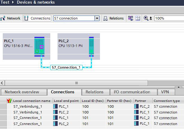
1) In the Network view you click the "Connections" button. This enables the Connection mode.
2) Select "S7 connection" as the connection type.
3) With the button held down drag the mouse cursor from the S7-1500 CPU where the S7 connection is to start to the S7-1500 CPU where the S7 connection is to finish.
4) Release the mouse button when the cursor is on the target device to create the S7 connection between the two S7-1500 CPUs.
Result
* A specified connection is created.
* The connection route is highlighted.
* The connection is entered in the connection table.
2.2 Properties of the Configured S7 Connection
The "Properties" tab in the Inspector window shows the properties of the S7 connection to be configured. These include:
* General connection parameters
* Local ID
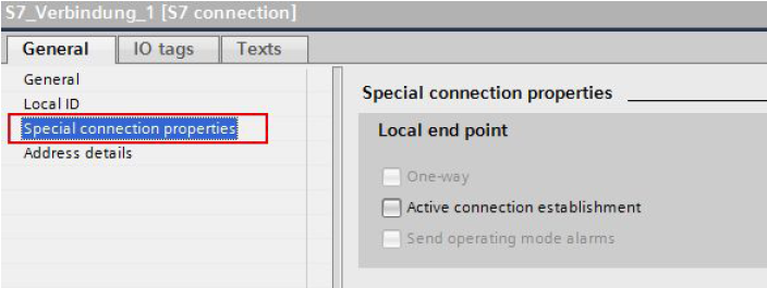
* Special connection parameters
* Address details
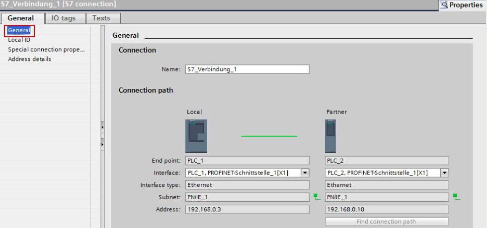
General connection parameters
The "General" parameters group of the properties of the S7 connection shows the general connection parameters that identify the connection endpoint. Here you can assign the connection route and specify the connection partner in full.
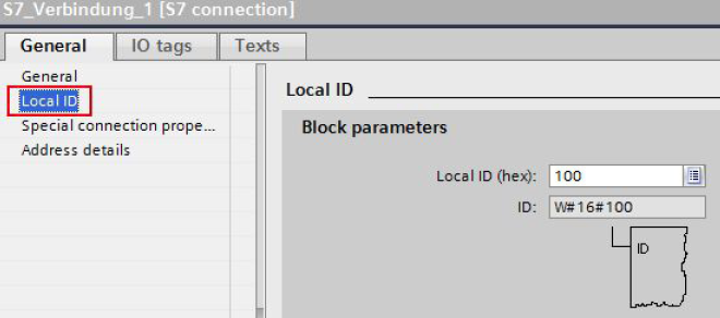
Local ID
Here you see the local ID of the module from which the S7 connection is observed (local partner). You can change the local ID. This is necessary if you have already
programmed communication function blocks and you want to use the local ID specified there for the S7 connection.
Special connection parameters
Display of the connection parameters
* One-way
One-way means that the connection partner is server for this connection and cannot actively send or receive.
* Active connection establishment
In this example a two-way S7 connection is configured. This means that you can set which connection partner is to take on the active part.
* Send operating mode alarms
In this example the local partner does not send any operating mode alarms to the connection partner.
Address details
Display of the address details of the S7 connection. In the case of an unspecified partner you can change the values for the rack and slot. All the other values are taken from the current configuration and cannot be changed.
2.3 Permit Access with PUT/GET Communication from Remote Partner (PLC, HMI, OPC, …)
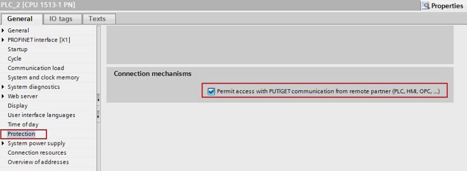
Access from the remote partner (PLC, HMI, OPC, …) with PUT/GET communication must be permitted for both S7-1500 CPUs between which the S7 connection is configured.
Select the CPU in the device configuration of the first S7-1500 station.
In the inspector window you enable the option "Permit access with PUT/GET communication from remote partner (PLC, HMI, OPC, …)" under "Properties > General > Protection".
Select the CPU in the device configuration of the second S7-1500 station. In the inspector window you enable the option "Permit access with PUT/GET communication from remote partner (PLC, HMI, OPC, …)" under "Properties > General > Protection".
Configure Clock Memory
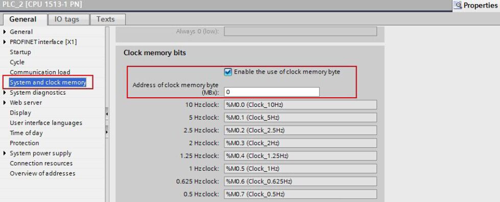
Memory byte 0 is configured as clock memory in the active S7-1500 CPU. The send and receive job is triggered by this clock memory.
Select the CPU in the device configuration of the S7-1500 station.
In the inspector window you enable the option "Enable the use of clock memory byte" under "Properties > General > System and clock memory". The address 0 is entered for the clock memory byte in this example.
3. User Program of the Active S7-1500 CPU
The user program of the active S7-1500 CPU consists of the following blocks:
| Block | Symbolic name | Description |
| OB100 | Startup | Startup OB The OB100 is executed when the CPU is restarted (warm restart). |
| OB1 | Main | The PUT_GET (FB1) block including the associated instance data block PUT_GET_DB (DB5) is called cyclically in OB1. |
| FB1 | PUT_GET | The communication instructions PUT and GET are called in the PUT_GET (FB1) block to transfer data via the configured S7 connection. |
| DB5 | PUT_GET_DB | Instance data block of the PUT_GET (FB1) block |
| DB1 | SEND_DATA | The data to be sent to the communication partner with the PUT instruction (send data) is stored in the SEND_DATA (DB1) block. |
| DB2 | RCVD_DATA | The data received from the communication partner with the GET instruction (receive data) is stored in the RCVD_DATA (DB2) data block. |
3.1 OB100
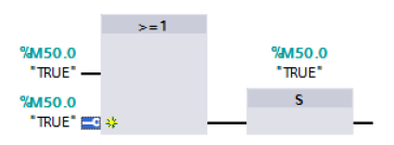
When you restart (warm restart) the CPU, the M50.0 "TRUE" is set to the value "1". With M50.0 "TRUE" the job to send or receive data is enabled.
3.2 OB1
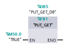
The PUT_GET (FB1) block including the associated instance data block PUT_GET_DB (DB5) is called cyclically in OB1.
3.3 PUT_GET (FB1)
3.3.1 Write data
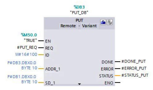
The PUT communication instruction is called in the PUT_GET (FB1) block. The PUT instruction is in the "Instructions" task card in the "Communication > S7 Communication" palette.
You use the PUT instruction to write data to the remote S7-1500 CPU.
Note:
This is only possible if the function "Permit access with PUT/GET communication from remote partner" has been enabled for the partner CPU in the Properties of the CPU under "Protection".
With the PUT instruction you cannot access blocks that have been created with the "optimized" type of access.
Input parameters of the PUT instruction
The PUT instruction has the following input parameters.
| Input parameters | Data type | Description |
| REQ | BOOLEAN | Control parameter, enables data transfer on rising edge |
| ID | WORD | Addressing parameter for specifying the connection to the partner CPU |
| ADDR_1 | REMOTE | Pointer to the area to be written to in the partner CPU. |
| SD_1 | VARIANT | Pointer to the area in your own CPU that contains the data to be sent. |
Output parameters of the PUT instruction
The PUT instruction has the following output parameters.
| Output parameters | Data type | Description |
| DONE | BOOLEAN | State parameter DONE 0: Job not yet started or is still being executed 1: Job executed error-free |
| ERROR | BOOLEAN | ERROR = 0 or ERROR = 1 |
| STATUS | WORD | State parameters ERROR and STATUS, error display ERROR = 0 STATUS has the value: – 0000H: neither warning nor error – <> 0000H: Warning, STATUS provides detailed information ERROR = 1 An error has occurred, STATUS provides detailed information about the type of error |
Enable job to write the data
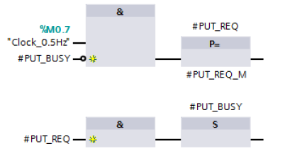
The job to write the data is enabled by a positive edge at the REQ input of the PUT instruction. Enabling of the write job is controlled by clock memory M0.7 and the "PUT_BUSY" variable. When the write job is running, “PUT_BUSY” is set to the value "1". This makes it impossible for a new send job to be triggered.
Only when the current write job has been completed successfully or with an error is “PUT_BUSY” reset to the value "0" so that a new write job can be enabled.
Setting connection parameters
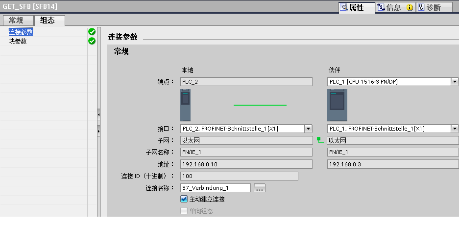
The connection parameters for the PUT instruction are set in the inspector window of the program editor. For this you select the PUT instruction called in the PUT_GET (FB1) block. Open the "Configuration" tab in the inspector window. The "Connection Parameters" group is in the "Configuration" tab in the area navigation. This group includes the connection parameters.
Define the connection endpoints of the S7 connection via which the data will be sent and received. In this example you select as partner the S7-1500 CPU that participates passively in establishing the configured S7 connection.
The interface type, interface name and address of the communication partners are entered automatically once you have defined the connection endpoint.
Select the name of the S7 connection via which the data is to be transferred. The ID of the selected S7 connection will be entered automatically at the ID parameter of the PUT instruction.
Receive data area in the partner CPU
At the ADDR_1 input parameter of the PUT instruction you specify the memory area of the partner CPU to which the data is to be written. Only absolute addressing is permitted. In this example 10 bytes of data are stored in DB3 of the partner CPU starting at address 0:
P#DB3.DBX0.0 BYTE 10.
Send data area in the local CPU
At the SD_1 input data area of the PUT instruction you specify the memory area of the local CPU from which the data is to be read. In this example 10 bytes of data are stored in DB1 of the local CPU starting at address 0:
P#DB1.DBX0.0 BYTE 10.
Error evaluation
If an error occurs during processing of the PUT instruction, the STATUS of the PUT instruction is stored in the static variable “SAVE_STATUS_PUT”.
If the PUT instruction is executed and completed successfully, the “SAVE_STATUS_PUT” variable is set to the value 33 (dec) = 21 (hex).
3.3.2 Read data
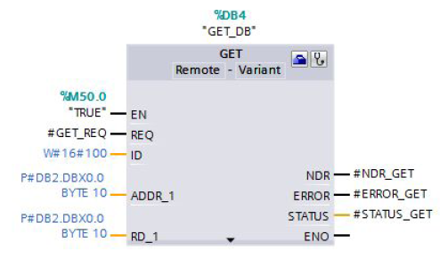
The GET communication instruction is called in the PUT_GET (FB1) block. The GET instruction is in the "Instructions" task card in the "Communication > S7 Communication" palette.
You use the GET instruction to read data from the remote S7-1500 CPU.
Note:
This is only possible if the function "Permit access with PUT/GET communication from remote partner" has been enabled for the partner CPU in the Properties of the CPU under "Protection".
With the GET instruction you cannot access blocks that have been created with the "optimized" type of access.
Input parameters of the GET instruction
The GET instruction has the following input parameters.
| Input parameters | Data type | Description |
| REQ | BOOLEAN | Control parameter, enables data transfer on rising edge |
| ID | WORD | Addressing parameter for specifying the connection to the partner CPU |
| ADDR_1 | REMOTE | Pointer to the area to be read to in the partner CPU. |
| RD_1 | VARIANT | Pointer to the area in your own CPU in which the read data is stored. |
Output parameters of the PUT instruction
The GET instruction has the following output parameters.
| Output parameters | Data type | Description |
| NDR | BOOLEAN | State parameter NDR 0: Job not yet started or is still being executed 1: Job executed error-free |
| ERROR | BOOLEAN | ERROR = 0 or ERROR = 1 |
| STATUS | WORD | State parameters ERROR and STATUS, error display ERROR = 0 STATUS has the value: – 0000H: neither warning nor error – <> 0000H: Warning, STATUS provides detailed information ERROR = 1 An error has occurred, STATUS provides detailed information about the type of error |
Enable job to read the data
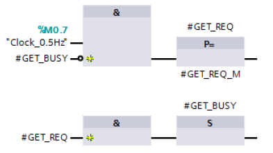
The job to read the data is enabled by a positive edge at the REQ input of the GET instruction. Enabling of the read job is controlled by clock memory M0.7 and the "GET_BUSY" variable. When the read job is running, “GET_BUSY” is set to the value "1". Triggering a new read job is not then possible.
Only when the current read job has been completed successfully or with an error is “GET_BUSY” reset to the value "0" so that a new read job can be enabled.

P#DB2.DBX0.0 BYTE 10


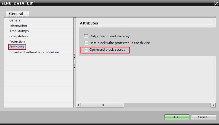
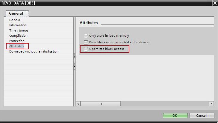
In the Properties of the SEND_DATA (DB1) data block you disable the "Optimized block access" function under "Attributes".
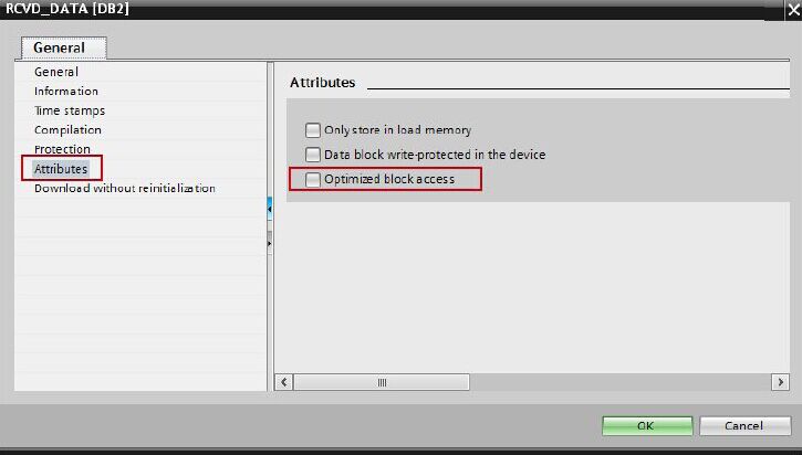
All you need are data blocks in which the sent and received data is stored.
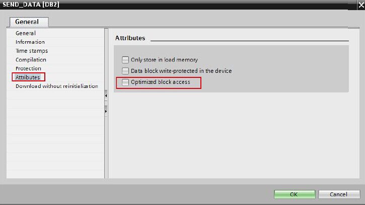
In the Properties of the RCVD_DATA (DB2) data block you disable the "Optimized block access" function under "Attributes".








 728
728

 被折叠的 条评论
为什么被折叠?


