


设备树的最终目的
提供一种语言来解析硬件配置信息
设备端:使用设备树之前
硬件的描述信息,放置在一个个arch/xxx/mach-xxx/board-xxx.c的C文件中
static struct resource dm9000_resource1[] ={

	{

		.start = 0x20100000,

		.end = 0x20100000 + 1,

		.flags = IORESOURCE_MEM

		…

		.start = IRQ_PF15,

		.end = IRQ_PF15,

		.flags = IORESOURCE_IRQ |IORESOURCE_IRQ_HIGHEDGE

	}

};

static struct platform_devicedm9000_device1 = {

	.name= "dm9000",

	.id= 0,

	.num_resources =ARRAY_SIZE(dm9000_resource1),

	.resource= dm9000_resource1,

};

static struct platform_device*ip0x_devices[] __initdata = {

	&dm9000_device1,

	&dm9000_device2,

};

static int __init ip0x_init(void)
{

	platform_add_devices(ip0x_devices, ARRAY_SIZE(ip0x_devices));

}
设备端,使用设备树之后
硬件的描述信息,放置到一个个arch/xxx/boot/dts目录下的.dtsi和dts文件中
arch/powerpc/boot/dts
arch/arm/boot/dts
…..
这些目录存在大量的dts文件
eth:eth4,c00000{

         compatible=”davicom,dm90000”;

         reg=<40x00c00000 0x2
	      40x00c00002 0x2>;
         Interrupt-parent=<&gpio2>;
	 Interrupt=<14 IRQ_TYPE_LEVEL_LOW>;

}
在使用device-tree之后,linux就会有大量的dts文件,但是设备驱动只有一份
驱动端:从DT拿硬件信息:drivers/xxx
static int dm9000_probe(structplatform_device *pdev)
{
	…
	db->addr_res =platform_get_resource(pdev, IORESOURCE_MEM, 0); 其实它可能就对应你节点里面的reg这个属性,其他的属性你可以去其他的API里面去拿,你可以看到很多的of开头的一些API,这些API就是帮你去拿device_tree下面的各种属性
	db->data_res =platform_get_resource(pdev, IORESOURCE_MEM, 1);

	db->irq_res  = platform_get_resource(pdev, IORESOURCE_IRQ,0);

	…

}

static struct platform_driver dm9000_driver= {

	.driver = {

		.name   = "dm9000",

		.pm     = &dm9000_drv_pm_ops,

		.of_match_table =of_match_ptr(dm9000_of_matches),

		},

	.probe  = dm9000_probe,

	.remove = dm9000_drv_remove,

};
device-tree的文件实际上是包括两种格式
第一个是dtsi,另一个是dts。Dts一般是最末尾的一级,dtsi是类是于大家写C语言,也有头文件和.c文件一样。
soc-abc.dtsi
有个节点a,下面有个属性b=c
a{
b=c;
}
然后在soc-abc2-boardd.dts引用了soc-abc.dtsi
然后有个a{
b=d;
}
然后这里a下面的属性b的值c就会被编译器去掉变成d;
这就叫底层覆盖上层,底层的DTS的属性可以改变上次的值
设备树的生命周期
首先你有个DTS的源文件,然后经过一个DTC的编译器,然后DTC会把DTB编译出DTB,你会把这个DTB烧到SD卡里面或者是flash里面,然后你的bootloadr会把这个DTB拷贝到DDR内存条里面,但是拷贝的时候可能会做一些改动,因为Bootloader也是支持DTB的,所以会把你的DTB做一些改动,然后linux kernel在启动过程中,就会在R2寄存器读出你这个基地址,然后FDT(平坦的设备树,就是连续占了一段内存)编程不平坦的expanded dt(就是把整个联系的内存解析成一个一个的设备节点)。
节点和属性,
i2c0: i2c@7f004000 {

	compatible ="samsung,s3c2440-i2c";

	reg =<0x7f004000 0x1000>;

	interrupt-parent= <&vic1>;

	interrupts =<18>;

	clock-names ="i2c";

	clocks =<&clocks PCLK_IIC0>;

	status ="disabled";

	#address-cells =<1>;

	#size-cells =<0>;

	g762@3e {

		compatible = "gmt,g762";

		reg = <0x3e>;

		clocks = <&g762_clk>;

	};

}
上面就是一个节点,这个节点下面有很多属性,这些字符串可以是字符串,可以是整数,还可以互相引用,有时候你会看到C语言里面的取地址符,比如说我的中断父是vic1,而vic1其实是另一个节点,
平时做device tree的时候就是三个地方
脚本文档 代码
比如下面的
omap5-sbc-t54.dts

&mmc1 {

	...

	cd-inverted;//反转

	wp-inverted; //写保护

	...

};
bool型的最好写,你写了上面那就话,bool型的就为真
上面的属性是bool型的
drivers/mmc/core/host.c

cd_cap_invert = of_property_read_bool(np,"cd-inverted");

ro_cap_invert = of_property_read_bool(np,"wp-inverted");
如果你没写那就话,你读cd_cap_invert = of_property_read_bool(np, "cd-
inverted");这个的时候,读到的就是假
然后看文档
Documentation/devicetree/bindings/mmc/mmc.txt

- cd-inverted: when present, polarity on the CD line is inverted. See the note below for the case, when a GPIO is used for the CD line
- wp-inverted: when present, polarity on the WP line is inverted. See the note below for the case, when a GPIO is used for the WP line
我们在来看一下一个U32数组节点属性的来龙去脉
tegra30.dtsi

arm,data-latency =<6 6 2>;
这三位整数在我们文档里面也有解释
Documentation/devicetree/

bindings/arm/l2cc.txt

- arm,data-latency : Cycles of latency for Data RAM accesses. Specifies 3 cells of read, write and setup latencies. Minimum valid values are 1. Controllers without setup latency control should use a value of 0.
这跟我们前面bool型不一样,是32位的整形数组,所以我们这里用的是读23位整形数组去读它
这样就把它读到C语言的data数组里面去了
arch/arm/mm/cache-l2x0.c
of_property_read_u32_array(np,"arm,data-latency",data, ARRAY_SIZE(data));
所以在LINUX里面有各种各有的API方便你去读
在include/linux/of.h里面定义
设备树里数据有三大作用
这个世界上有这么多的电路板,这么多的芯片,linux kernel起来了首先应该知道我是哪一个板子,所以device tree首先标识我是哪一块板子,这就是平台标识。这个平台标识是通过你device tree根节点的兼容性字段的属性来得到的
用DT来标识特定的machine;root节点的compatible字段,匹配machine_desc的dt_compat
比如:
compatible ="ti,omap3-beagleboard","ti,omap3450","ti,omap3";所以你根节点下的兼容性字段的属性就是你芯片的类型,linux内核有方法去获取到这个信息,从而知道你是一块什么板第二个是运行时配置chosen节点的属性
chosen {
	bootargs ="console=ttyS0,115200
	loglevel=8";
	initrd-start =<0xc8000000>;
	initrd-end =<0xc8200000>;
};
最后是
设备信息集合device population
serial@70006300 {

    compatible ="nvidia,tegra20-uart";

    reg = <0x70006300 0x100>;

    interrupts = <122>;

};
平台标识的实现
这些芯片进去之后都会有个DT_MACHINE_START,里面描述了一些DT_MACHINE
这些DT_MACHINE一般都是这样的
DT_MACHINE_START(OMAP242X_DT, "GenericOMAP2420 (Flattened Device Tree)")

         .reserve   = omap_reserve,

         .map_io             = omap242x_map_io,

         .init_early         = omap2420_init_early,

         .init_machine  = omap_generic_init,

         .init_time = omap_init_time,

         .dt_compat      = omap242x_boards_compat,

         .restart    = omap2xxx_restart,

MACHINE_END
DT_MACHINE_START和MACHINE_END之间是你这个芯片和你这个电路板特定的一些初始化的代码,所以linux下会有很多这个DT_MACHINE,到底执行的是那个DT_MACHINE,每个DT_MACHINE下面都会有个.dt_compat =omap242x_boards_compat,
这就你那个DT_MACHINE所兼容的板和芯片
static const char *constomap242x_boards_compat[] __initconst = {

         "ti,omap2420",

         NULL,

};
上面这个例子就是兼容的"ti,omap2420",有个电路板的根节点的compatible字段
运行时配置-U-Boot修改dtb
用户设置的bootarg就是这样传给设备树的
int fdt_chosen(void *fdt)
{
int nodeoffset;
int err;
char *str;
/* used to set string properties */
err = fdt_check_header(fdt);
...
/* find or create "/chosen" node.*/
nodeoffset = fdt_find_or_add_subnode(fdt,0, "chosen");
...
str = getenv("bootargs");
if (str) {
err = fdt_setprop(fdt, nodeoffset,"bootargs", str,
strlen(str) + 1);
...
}
...
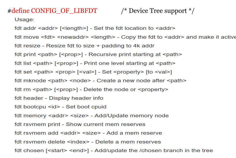
}Uboot里面有很多设置device tree的命令
Ranges属性代表了local地址向parent地址转换
ranges为空表示1:1映射
无range代表不是memory map区域
Ranges(local地址,parents地址,size)
举例如下
mpcore {
    compatible = "simple-bus";
    ranges = <0x00000000 0x19020000 0x00003000>;
    #address-cells = <1>;
    #size-cells = <1>;
    scu@0000 {
        compatible = "arm,cortex-a9-scu";
        reg = <0x0000 0x100>;
    };
    timer@0200 {
        compatible = "arm,cortex-a9-global-timer";
        reg = <0x0200 0x100>;
        interrupts = <GIC_PPI 11 IRQ_TYPE_LEVEL_HIGH>;
        clocks = <&clk_periph>;
    };
}设备与驱动的匹配
eth: eth@4,c00000 {
    compatible = "davicom,dm9000";
    …
};

#ifdef CONFIG_OF
static const struct of_device_id dm9000_of_matches[] = {
    { .compatible = "davicom,dm9000", },
    { /* sentinel */ }
};

MODULE_DEVICE_TABLE(of, dm9000_of_matches);
#endif

static struct platform_driver dm9000_driver = {
    .driver = {
        .name    = "dm9000",
        .pm      = &dm9000_drv_pm_ops,
        .of_match_table = of_match_ptr(dm9000_of_matches),
    },
    .probe   = dm9000_probe,
    .remove  = dm9000_drv_remove,
}; static const struct of_device_id dm9000_of_matches[] = {
{ .compatible = "davicom,dm9000", },
{ /* sentinel */ }
};
这个.compatible一致就匹配上了,匹配上了就可以调用probe函数了
下面是拿到data的操作。
drivers/dma/sun6i-dma.c
static struct sun6i_dma_config sun8i_a23_dma_cfg = {
	.nr_max_channels = 8,
	.nr_max_requests = 24,
	.nr_max_vchans   = 37,
};
static struct of_device_id sun6i_dma_match[] = {
	{ .compatible = "allwinner,sun6i-a31-dma", .data = &sun6i_a31_dma_cfg },
	{ .compatible = "allwinner,sun8i-a23-dma", .data = &sun8i_a23_dma_cfg },
	{ /* sentinel */ }
};
static int sun6i_dma_probe(struct platform_device *pdev)
{
	...
	device = of_match_device(sun6i_dma_match, &pdev->dev);
	if (!device)
	return -ENODEV;
	sdc->cfg = device->data
}
device tree下面的关键属性,第一个是reg(寄存器等)属性,这个一般是描述你的基地址和地址size
每个总线下面都会有一个#address-cells = <1> 和#size-cells = <1>;这个是说你地址需要多少个数据来描述,你的size要多少个数据来描述
举个例子
soc@0 {
    #address-cells = <1>;
    #size-cells = <1>;
    compatible = "intel,ce4100-cp";
    ranges;
    ioapic1: interrupt-controller@fec00000 {
            #interrupt-cells = <2>;
            compatible = "intel,ce4100-ioapic";
            interrupt-controller;
            reg = <0xfec00000  0x1000>;
};
因为我soc总线的#address-cells = <1>; #size-cells = <1>;都是1,所以我reg = <0xfec00000 0x1000>;前面的就是address,后面的就是size了
i2c-controller@b,2 {
    #address-cells = <2>;
    #size-cells = <1>;
    ...
    i2c@0 {
        reg = <0 0 0x100>;
    };
}
但是你看上面这一条,I2c控制器接到某一天总线上,但是这个总线的地址比如说是64位的,我就需要2个32位的整数来描述,reg = <0 0 0x100>;地址占两个整数
size占一个整数
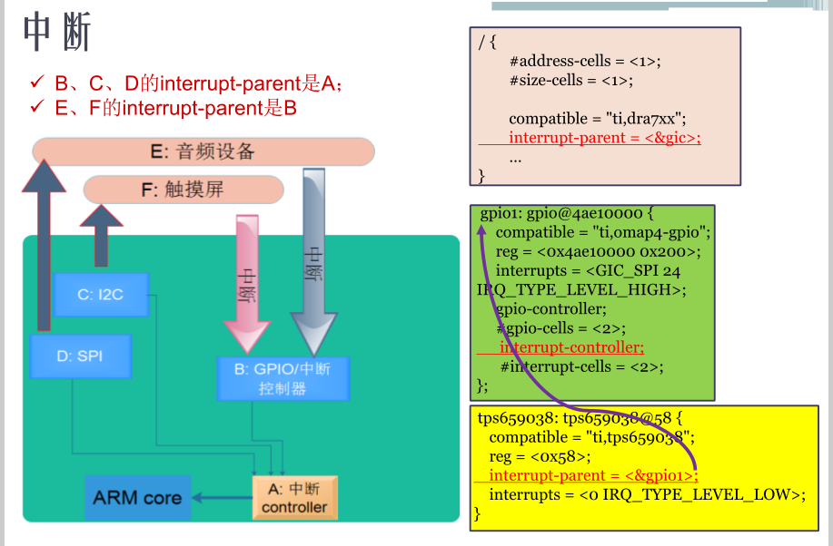
上图的解析:绿色的部分是SOC,


 3866
3866

 被折叠的 条评论
为什么被折叠?
被折叠的 条评论
为什么被折叠?
 到【灌水乐园】发言


