


实验top
实验要求:
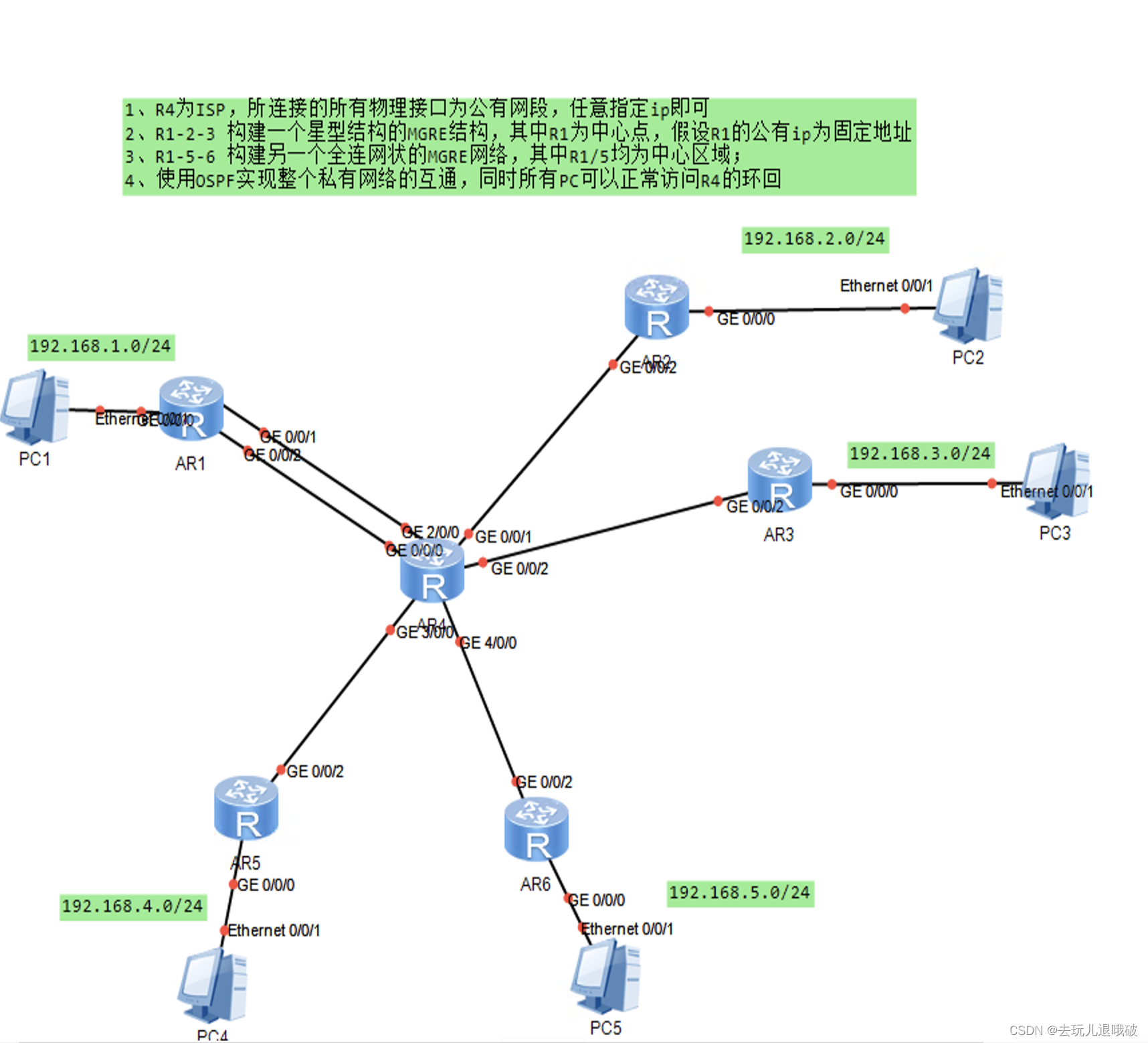
1、R4为ISP,所连接的所有物理接口为公有网段,任意指定ip即可
2、R1-2-3 构建一个星型结构的MGRE结构,其中R1为中心点,假设R1的公有ip为固定地址
3、R1-5-6 构建另一个全连网状的MGRE网络,其中R1/5均为中心区域;
4、使用OSPF实现整个私有网络的互通,同时所有PC可以正常访问R4的环回
实验步骤:
第一步:IP地址规划
PC地址
PC1 192.168.1.2 24 网关192.168.1.1 24
PC2 192.168.2.2 24 网关192.168.2.1 24
PC3 192.168.3.2 24 网关192.168.3.1 24
PC4 192.168.4.2 24 网关192.168.4.1 24
PC5 192.168.5.2 24 网关192.168.5.1 24
设备地址
R1 g0/0/0 192.168.1.1 24 g0/0/1 16.1.1.1 24 g0/0/2 61.1.1.1 24
R2 g0/0/0 192.168.2.1 24 g0/0/1 26.1.1.2 24
R3 g0/0/0 192.168.3.1 24 g0/0/1 36.1.1.3 24
R4 g0/0/0 162.168.4.1 24 g0/0/1 46.1.1.4 24
R5 g0/0/0 192.168.5.1 24 g0/0/1 56.1.1.5 24
R6 g0/0/0 16.1.1.6 24 g2/0/0 61.1.1.6 24 g0/0/1 26.1.1.6 24
g0/0/2 36.1.1.6 24 g3/0/0 56.1.1.6 24 g4/0/0 46.1.1.6 24
第二步:配置IP地址
R1配置
[R1]int g0/0/0
[R1-GigabitEthernet0/0/0]ip add 192.168.1.1 24
[R1]int g0/0/1
[R1-GigabitEthernet0/0/1]ip add 16.1.1.1 24
[R1]int g0/0/2
[R1-GigabitEthernet0/0/2]ip add 61.1.1.1 24
R2配置
[R2]int g0/0/0
[R2]GigabitEthernet0/0/0]ip add 192.168.2.1 24
[R2]int g0/0/1
[R1-GigabitEthernet0/0/2]ip add 61.1.1.1 24
R2配置
[R2]int g0/0/0
[R2]GigabitEthernet0/0/0]ip add 192.168.2.1 24
[R2]int g0/0/1
[R2]GigabitEthernet0/0/1]ip add 26.1.1.2 24
R3配置
[R3]int g0/0/0
[R3-GigabitEthernet0/0/0]ip add 192.168.3.1 24
[R3]int g0/0/1
[R3-GigabitEthernet0/0/1]ip add 36.1.1.3 24
R4配置
[R4]int g0/0/0
[R4-GigabitEthernet0/0/0]ip add 192.168.4.1 24
[R4]int g0/0/1
[R4-GigabitEthernet0/0/1]ip add 46.1.1.4 24
R5配置
[R5]int g0/0/0
[R5-GigabitEthernet0/0/0]ip add 192.168.5.1 24
[R5]int g0/0/1
[R5-GigabitEthernet0/0/1]ip add 56.1.1.5 24
R6配置
[R6]int g0/0/0
[R6-GigabitEthernet0/0/0]ip add 16.1.1.6 24
[R6]int g2/0/0
[R6-GigabitEthernet0/0/0]ip add 61.1.1.6 24
[R6]int g0/0/1
[R6-GigabitEthernet0/0/0]ip add 26.1.1.6 24
[R6]int g0/0/2
[R6-GigabitEthernet0/0/0]ip add 36.1.1.6 24
[R6]int g3/0/0
[R6-GigabitEthernet0/0/0]ip add 56.1.1.6 24
[R6]int g4/0/0
[R6-GigabitEthernet0/0/0]ip add 46.1.1.6 24
第三步:配置缺省路由
[R1]ip route-static 0.0.0.0 0 16.1.1.6
[R2]ip route-static 0.0.0.0 0 26.1.1.6
[R3]ip route-static 0.0.0.0 0 36.1.1.6
[R4]ip route-static 0.0.0.0 0 46.1.1.6
[R5]ip route-static 0.0.0.0 0 56.1.1.6
第四步:NAT
[R1]acl 2000
[R1-acl-basic-2000]rule 1 permit source any
[R1]int g 0/0/1
[R1-GigabitEthernet0/0/1]nat outbound 2000
R2配置
[R2]acl 2000
[R2-acl-basic-2000]rule 1 permit source any
[R2]int g 0/0/1
[R2-GigabitEthernet0/0/1]nat outbound 2000
R4配置
[R4]acl 2000
[R4-acl-basic-2000]rule 1 permit source any
[R4]int g 0/0/1
[R4-GigabitEthernet0/0/1]nat outbound 2000
R5配置
[R5]acl 2000
[R5-acl-basic-2000]rule 1 permit source any
[R5]int g 0/0/1
[R5-GigabitEthernet0/0/1]nat outbound 2000
第五步:R1R2R3构建星型MGRE结构
R1配置
[R1]interface Tunnel 0/0/0
[R1-Tunnel0/0/0]ip address 10.1.1.1 24
[R1-Tunnel0/0/0]tunnel-protocol gre p2mp
[R1-Tunnel0/0/0]source 61.1.1.1
[R1-Tunnel0/0/0]nhrp network-id 100
R2配置
[R2]interface Tunnel 0/0/0
[R2-Tunnel0/0/0]ip address 10.1.1.2 24
[R2-Tunnel0/0/0]tunnel-protocol gre p2mp
[R2-Tunnel0/0/0]source g0/0/1
[R2-Tunnel0/0/0]nhrp entry 10.1.1.1 61.1.1.1 register
[R2-Tunnel0/0/0]nhrp network-id 100
R3配置
[R3]interface Tunnel 0/0/0
[R3-Tunnel0/0/0]ip address 10.1.1.3 24
[R3-Tunnel0/0/0]tunnel-protocol gre p2mp
[R3-Tunnel0/0/0]source g0/0/1
[R3-Tunnel0/0/0]nhrp entry 10.1.1.1 61.1.1.1 register
[R3-Tunnel0/0/0]nhrp network-id 100
第六步:R1R4R5构建全连网状的MGRE结构
R1配置
[R1]interface Tunnel 0/0/1
R1配置
[R1]interface Tunnel 0/0/1
[R1-Tunnel0/0/1]ip address 20.1.1.1 24
[R1-Tunnel0/0/1]tunnel-protocol gre p2mp
[R1-Tunnel0/0/1]source 16.1.1.1
[R1-Tunnel0/0/1]nhrp network-id 101
[R1-Tunnel0/0/1]nhrp entry 20.1.1.2 46.1.1.4 register
[R1-Tunnel0/0/1]nhrp entry 20.1.1.3 56.1.1.5 register
R4配置
[R4]interface Tunnel 0/0/1
[R4-Tunnel0/0/1]ip address 20.1.1.2 24
[R4-Tunnel0/0/1]tunnel-protocol gre p2mp
[R4-Tunnel0/0/1]source 46.1.1.4
[R4-Tunnel0/0/1]nhrp network-id 101
[R4-Tunnel0/0/1]nhrp entry 20.1.1.1 16.1.1.1 register
[R4-Tunnel0/0/1]nhrp entry 20.1.1.3 56.1.1.5 register
R5配置
[R5]interface Tunnel 0/0/1
[R5-Tunnel0/0/1]ip address 20.1.1.3 24
[R5-Tunnel0/0/1]tunnel-protocol gre p2mp
[R5-Tunnel0/0/1]source 56.1.1.5
[R5-Tunnel0/0/1]nhrp network-id 101
[R5-Tunnel0/0/1]nhrp entry 20.1.1.1 16.1.1.1 register
[R5-Tunnel0/0/1]nhrp entry 20.1.1.2 46.1.1.4 register
第七步:书写OSPF
R1配置
[R1]ospf 1 router-id 1.1.1.1
[R1-ospf-1]area 0
[R1-ospf-1-area-0.0.0.0]network 20.1.1.0 0.0.0.255
[R1-ospf-1-area-0.0.0.0]network 10.1.1.0 0.0.0.255
[R1-ospf-1-area-0.0.0.0]network 192.168.1.0 0.0.0.255
第八步:将p2p修改为bordcast
R1配置
[R1]interface Tunnel 0/0/0
[R1-Tunnel0/0/0]ospf network-type broadcast
[R1]interface Tunnel 0/0/1
[R1-Tunnel0/0/1]ospf network-type broadcast
R2配置
[R2]interface Tunnel 0/0/0
[R2-Tunnel0/0/0]ospf network-type broadcast
R3配置
[R3]interface Tunnel 0/0/0
[R3-Tunnel0/0/0]ospf network-type broadcast
R4配置
[R4]interface Tunnel 0/0/1
[R4-Tunnel0/0/1]ospf network-type broadcast
R5配置
[R5]interface Tunnel 0/0/1
[R5-Tunnel0/0/1]ospf network-type broadcast
第九步:开启伪广播
R1配置
[R1]interface Tunnel 0/0/0
[R1-Tunnel0/0/0]nhrp entry multicast dynamic
[R1]interface Tunnel 0/0/1
[R1-Tunnel0/0/1]nhrp entry multicast dynamic
R4配置
[R4]interface Tunnel 0/0/1
[R4-Tunnel0/0/1]nhrp entry multicast dynamic
R5配置
[R5]interface Tunnel 0/0/1
[R5-Tunnel0/0/1]nhrp entry multicast dynamic
第十步:修改优先级
R2配置
[R2]interface Tunnel 0/0/0
[R2-Tunnel0/0/0]ospf dr-priority 0
R3配置
[R3]interface Tunnel 0/0/0
[R3-Tunnel0/0/0]ospf dr-priority 0


 562
562


 被折叠的 条评论
为什么被折叠?
被折叠的 条评论
为什么被折叠?
 到【灌水乐园】发言


