


一.ps2手柄介绍
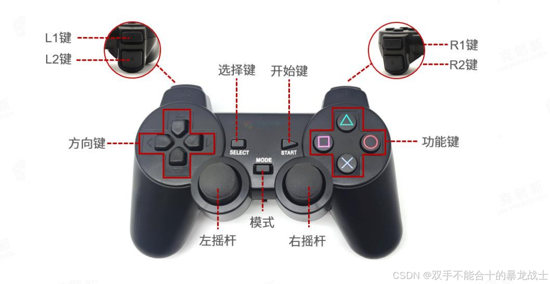
手柄按键定义如下图,具有 2 个 360°摇杆和 17 个物理按键,摇杆也可以作为按键使用。
手柄通过 2 节 7 号电池供电,使用前请安装电池。并将下图所示开关打开,拨动到 ON 一侧
为打开。
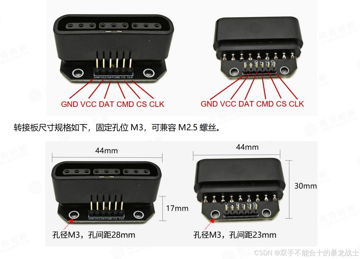
下图为转接板。
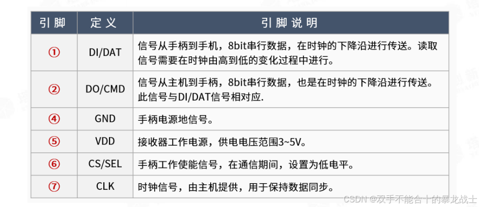
下图为引脚定义
1-DATA:信号流向从手柄到主机。此信号是一个 8 bit 的串行数据,同步传送于时钟下降沿
(输入输出信号在时钟信号由高 到低时变化,所有信号的读取在时钟前沿到电平变化之前完成。)
2-COMMAND :信号流向从主机到手柄。此信号和 DATA 相对,同样是一个 8 bit 的串行
数据,同步传送于时钟下降沿。
3-N/C (9 Volts unused)
4-GND
5-VCC :电源电压从 5V 到 3V 原装的索尼手柄都可以工作。主机主板上装有表面安装的
750mA 保险丝 ,用于防止外设过载
(750mA 是包括左右手柄和记忆卡)。
6-ATT :用于提供手柄触发信号。信号在通信期间处于低电平。又有人将此针脚叫做 CS。
7-CLOCK :信号流向从主机到手柄。用于保持数据同步。
8-N/C
9-ACK :从手柄到主机的应答信号。此信号在每个 8 bits 数据发送之后的最后一个时钟周期
变低,并且 ATT 一直保低电平。如果 ACK 信号不变低约 60 微秒 PS 主机会试另一个外设。
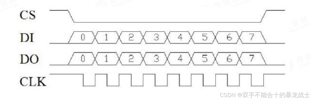
PS 手柄信号,所有通讯都是 8 bit 串行数据最低有效位先行。在 PS 手柄总线的所有时码在时
钟下降沿都是同步的。传送一个字节的情况如下所示。数据线的逻辑电平在时钟下降沿驱动下触发
改变。数据的接收读取在时钟的前沿(在记号*处)到电平变化之前完成。 在被选手柄接收每个
COMMAND 信号之后,手柄需拉低 ACK 电平在最后一个时钟。如果被选手柄没 ACK 应答主机
将假定没手柄接入。
当 PS 主机想读一个手柄的数据时,将会拉低 ATT 线电平并发出一个开始命令 (0x01)。手柄
将会回复它的 ID (0x41=数字, 0x23=NegCon, 0x73=工作模式). 在手柄发送 ID 字节的同时主机
将传送 0x42 请求数据。随后命令线将空闲和手柄送出 0x5A 意思说:“数据来了”。
字节定义如下。左右摇杆模拟值为无效,推到极限时,对应发送
UP、RIGHT、DOWN、
LEFT、△、〇、X、□,按键 L3、R3 无效。
二.cubeide配置
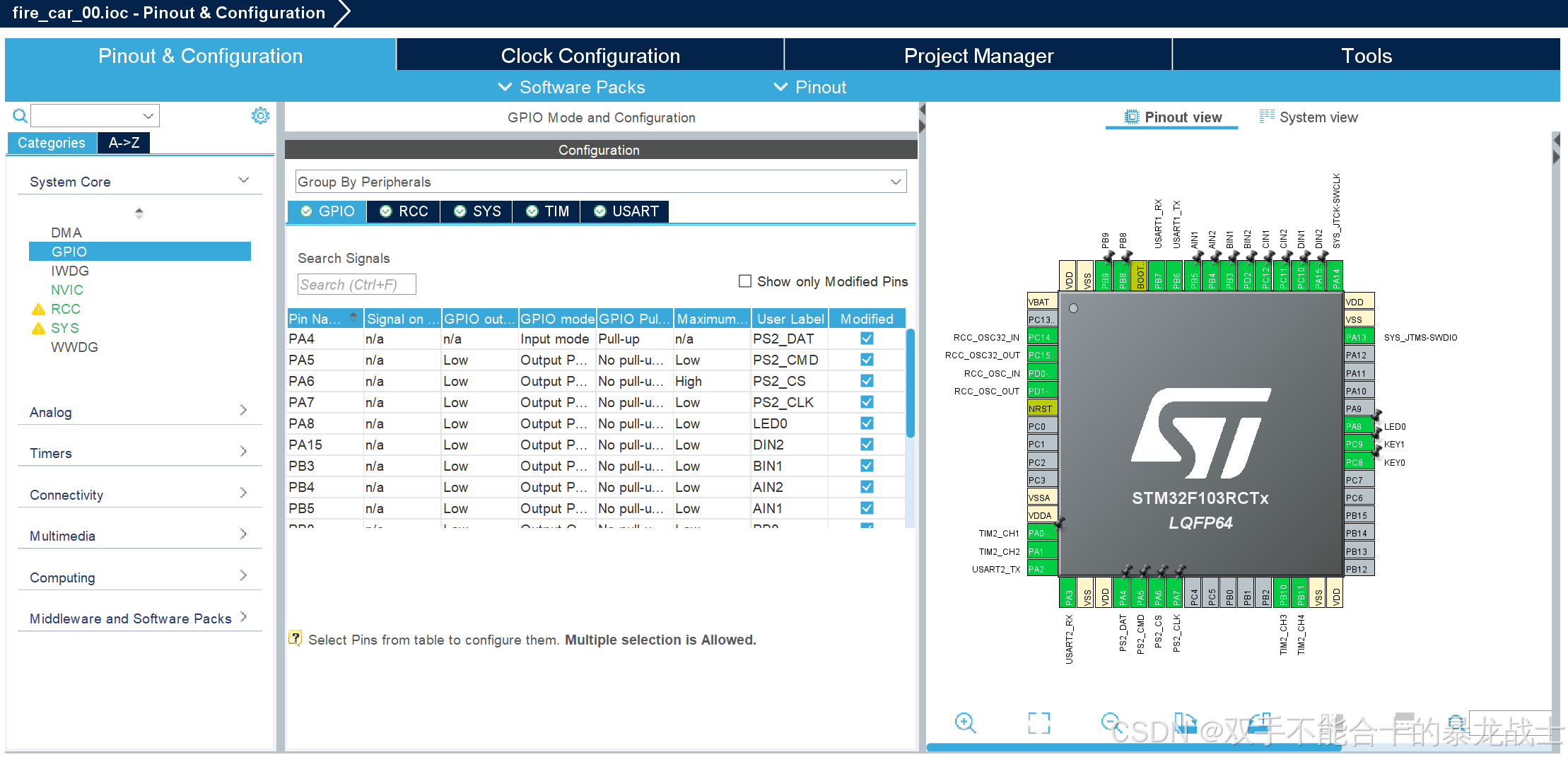
硬件连接关系如下。
GND——GND
VCC——3.3V 或 5V
DATA——PA4
CMD——PA5
CS——PA6
CLK——PA7
(后续关于其他的配置会给出)
三.微秒级延时
ps2需要一个us级的延时函数,所以需要自建一个delay函数
我这里用的是定时器模拟
1.delay.c
#include "delay.h"
#include "tim.h"


/**
  * @brief  微秒级延时(基于通用定时器,如 TIM2)
  * @param  htim: 定时器句柄(例如 &htim2)
  * @param  us: 延时的微秒数(范围:1 ~ 65535)
  */
void delay_us(TIM_HandleTypeDef *htim, uint32_t us)
{
  __HAL_TIM_SET_COUNTER(htim, 0);                        // 重置计数器
  HAL_TIM_Base_Start(htim);                              // 启动定时器

  while (__HAL_TIM_GET_COUNTER(htim) < us);              // 等待计数器达到目标值

  HAL_TIM_Base_Stop(htim);                               // 停止定时器
}
2.delay.h
#ifndef BSP_DELAY_H_
#define BSP_DELAY_H_

#include "main.h"

void delay_us(TIM_HandleTypeDef *htim, uint32_t us);

#endif /* BSP_DELAY_H_ */
四.ps2手柄解码
1.ps2.c
#include "ps2_0.h"
#include "delay.h"
#include "tim.h"

uint8_t PS2_RawData[9] = {0}; //存储原始数据的数组
PS2_TypeDef PS2_Data = {0};	//存储解码后数据的结构体

/*
 * PS2_CS函数的作用是控制PS2设备的片选信号(chip select)。
 * 在嵌入式系统中,片选信号通常用于控制多个设备的数据传输。
 * 当需要与某个设备进行通信时,将该设备的片选信号置为低电平,以使该设备接受数据传输。
 * 在与该设备的通信结束后,将该设备的片选信号置为高电平,以防止其他设备误接受数据传输。
 * 因此,PS2_CS函数是用来控制与PS2设备通信的时序和片选信号的函数。
 */

void PS2_CS(uint8_t Val)
{
    if (Val)
        HAL_GPIO_WritePin(PS2_CS_GPIOx, PS2_CS_Pin, GPIO_PIN_SET);
    else
        HAL_GPIO_WritePin(PS2_CS_GPIOx, PS2_CS_Pin, GPIO_PIN_RESET);
}


void PS2_CLK(uint8_t Val)
{
    if (Val)
        HAL_GPIO_WritePin(PS2_CLK_GPIOx, PS2_CLK_Pin, GPIO_PIN_SET);
    else
        HAL_GPIO_WritePin(PS2_CLK_GPIOx, PS2_CLK_Pin, GPIO_PIN_RESET);
}

void PS2_DO(uint8_t Val)
{
    if (Val)
        HAL_GPIO_WritePin(PS2_DO_GPIOx, PS2_DO_Pin, GPIO_PIN_SET);
    else
        HAL_GPIO_WritePin(PS2_DO_GPIOx, PS2_DO_Pin, GPIO_PIN_RESET);
}
uint8_t PS2_Read_DI()
{
    return HAL_GPIO_ReadPin(PS2_DI_GPIOx, PS2_DI_Pin);
}

uint8_t PS2_ReadWrite_Byte(uint8_t TxData)
{
    uint8_t TX = TxData;
    uint8_t RX = 0;
    for (int i = 0; i < 8; i++)
    {
        if (TX & 0x01)
            PS2_DO(1);
        else
            PS2_DO(0);
        TX >>= 1;
        PS2_CLK(1);
        delay_us(&htim4,50);
        PS2_CLK(0);
        RX >>= 1;
        RX |= (PS2_Read_DI() << 7);
        delay_us(&htim4,50);
        PS2_CLK(1);
        delay_us(&htim4,50);
    }
    return RX;
}

void PS2_Decode()
{
    if (PS2_RawData[2] == 0x5A)
    {
        PS2_Data.Key_Select = (~PS2_RawData[3] >> 0) & 0x01; //选择键
        PS2_Data.Key_Start = (~PS2_RawData[3] >> 3) & 0x01;  //开始键

        //左侧按键
        PS2_Data.Key_L_Up = (~PS2_RawData[3] >> 4) & 0x01;
        PS2_Data.Key_L_Right = (~PS2_RawData[3] >> 5) & 0x01;
        PS2_Data.Key_L_Down = (~PS2_RawData[3] >> 6) & 0x01;
        PS2_Data.Key_L_Left = (~PS2_RawData[3] >> 7) & 0x01;

        //后侧按键
        PS2_Data.Key_L2 = (~PS2_RawData[4] >> 0) & 0x01;
        PS2_Data.Key_R2 = (~PS2_RawData[4] >> 1) & 0x01;
        PS2_Data.Key_L1 = (~PS2_RawData[4] >> 2) & 0x01;
        PS2_Data.Key_R1 = (~PS2_RawData[4] >> 3) & 0x01;

        //右侧按键
        PS2_Data.Key_R_Up = (~PS2_RawData[4] >> 4) & 0x01;
        PS2_Data.Key_R_Right = (~PS2_RawData[4] >> 5) & 0x01;
        PS2_Data.Key_R_Down = (~PS2_RawData[4] >> 6) & 0x01;
        PS2_Data.Key_R_Left = (~PS2_RawData[4] >> 7) & 0x01;

        if (PS2_RawData[1] == 0x41)
        { //无灯模式(摇杆值八向)
            PS2_Data.Rocker_LX = 127 * (PS2_Data.Key_L_Right - PS2_Data.Key_L_Left);
            PS2_Data.Rocker_LY = 127 * (PS2_Data.Key_L_Up - PS2_Data.Key_L_Down);

            PS2_Data.Rocker_RX = 127 * (PS2_Data.Key_R_Right - PS2_Data.Key_R_Left);
            PS2_Data.Rocker_RY = 127 * (PS2_Data.Key_R_Up - PS2_Data.Key_R_Down);
        }
        else if (PS2_RawData[1] == 0x73)
        { //红灯模式(摇杆值模拟)

            //摇杆按键
            PS2_Data.Key_Rocker_Left = (~PS2_RawData[3] >> 1) & 0x01;
            PS2_Data.Key_Rocker_Right = (~PS2_RawData[3] >> 2) & 0x01;

            //摇杆值
            PS2_Data.Rocker_LX = PS2_RawData[7] - 0x80;
            PS2_Data.Rocker_LY = -1 - (PS2_RawData[8] - 0x80);
            PS2_Data.Rocker_RX = PS2_RawData[5] - 0x80;
            PS2_Data.Rocker_RY = -1 - (PS2_RawData[6] - 0x80);
        }
    }
}
void PS2_Read_Data(void)
{
    PS2_CS(0);
    PS2_RawData[0] = PS2_ReadWrite_Byte(0x01); // 0
    PS2_RawData[1] = PS2_ReadWrite_Byte(0x42); // 1
    for (int i = 2; i < 9; i++)
        PS2_RawData[i] = PS2_ReadWrite_Byte(0xff);
    PS2_CS(1);
    PS2_Decode();
}
2.ps2.h
#ifndef BSP_PS2_0_H_
#define BSP_PS2_0_H_

#include "main.h"


/*
需要4个GPIO:
3个推挽输出模式 CLK DO CS
1个上拉输入模式 DI
*/

#define PS2_CS_GPIOx GPIOA
#define PS2_CS_Pin GPIO_PIN_6

#define PS2_CLK_GPIOx GPIOA
#define PS2_CLK_Pin GPIO_PIN_7

#define PS2_DO_GPIOx GPIOA
#define PS2_DO_Pin GPIO_PIN_5

#define PS2_DI_GPIOx GPIOA
#define PS2_DI_Pin GPIO_PIN_4

typedef struct
{
    uint8_t A_D;                                       //模拟(红灯)为1 数字(无灯)为0
    int8_t Rocker_RX, Rocker_RY, Rocker_LX, Rocker_LY; //摇杆值(模拟状态为实际值0-0xFF)(数字态为等效的值0,0x80,0xFF)
    //按键值0为未触发,1为触发态
    uint8_t Key_L1, Key_L2, Key_R1, Key_R2;                //后侧大按键
    uint8_t Key_L_Right, Key_L_Left, Key_L_Up, Key_L_Down; //左侧按键
    uint8_t Key_R_Right, Key_R_Left, Key_R_Up, Key_R_Down; //右侧按键
    uint8_t Key_Select;                                    //选择键
    uint8_t Key_Start;                                     //开始键
    uint8_t Key_Rocker_Left, Key_Rocker_Right;             //摇杆按键

} PS2_TypeDef;

extern PS2_TypeDef PS2_Data;

void PS2_Read_Data(void);

#endif /* BSP_PS2_0_H_ */
五.ps2手柄按键及摇杆测试
1.main.c
/* USER CODE BEGIN Header */
/**
  ******************************************************************************
  * @file           : main.c
  * @brief          : Main program body
  ******************************************************************************
  * @attention
  *
  * Copyright (c) 2025 STMicroelectronics.
  * All rights reserved.
  *
  * This software is licensed under terms that can be found in the LICENSE file
  * in the root directory of this software component.
  * If no LICENSE file comes with this software, it is provided AS-IS.
  *
  ******************************************************************************
  */
/* USER CODE END Header */
/* Includes ------------------------------------------------------------------*/
#include "main.h"
#include "tim.h"
#include "usart.h"
#include "gpio.h"

/* Private includes ----------------------------------------------------------*/
/* USER CODE BEGIN Includes */
#include <stdarg.h>
#include "stdio.h"
#include "OLED.h"
#include "delay.h"
#include "Motor.h"
#include "Key.h"
#include "Led.h"
#include "ps2.h"
#include "ps2_0.h"
#include "openmv.h"
/* USER CODE END Includes */

/* Private typedef -----------------------------------------------------------*/
/* USER CODE BEGIN PTD */

/* USER CODE END PTD */

/* Private define ------------------------------------------------------------*/
/* USER CODE BEGIN PD */

/* USER CODE END PD */

/* Private macro -------------------------------------------------------------*/
/* USER CODE BEGIN PM */

/* USER CODE END PM */

/* Private variables ---------------------------------------------------------*/

/* USER CODE BEGIN PV */

/* USER CODE END PV */

/* Private function prototypes -----------------------------------------------*/
void SystemClock_Config(void);
/* USER CODE BEGIN PFP */

/* USER CODE END PFP */

/* Private user code ---------------------------------------------------------*/
/* USER CODE BEGIN 0 */

/* USER CODE END 0 */

/**
  * @brief  The application entry point.
  * @retval int
  */
int main(void)
{

  /* USER CODE BEGIN 1 */

  /* USER CODE END 1 */

  /* MCU Configuration--------------------------------------------------------*/

  /* Reset of all peripherals, Initializes the Flash interface and the Systick. */
  HAL_Init();

  /* USER CODE BEGIN Init */

  /* USER CODE END Init */

  /* Configure the system clock */
  SystemClock_Config();

  /* USER CODE BEGIN SysInit */

  /* USER CODE END SysInit */

  /* Initialize all configured peripherals */
  MX_GPIO_Init();
  MX_TIM1_Init();
  MX_TIM2_Init();
  MX_USART1_UART_Init();
  MX_USART2_UART_Init();
  MX_TIM3_Init();
  MX_TIM4_Init();
  /* USER CODE BEGIN 2 */
  /***********锟斤拷始锟斤拷***********/
  OLED_Init();
  Motor_Init();

  /* USER CODE END 2 */

  /* Infinite loop */
  /* USER CODE BEGIN WHILE */
  while (1)
  {
	  PS2_Read_Data();

	if(PS2_Data.Key_L_Up)
	{
		Motor_Set_Speed(1000,1000,1000, 1000);
	}
	else if(PS2_Data.Key_L_Down)
	{
		Motor_Set_Speed(-1000,-1000,-1000, -1000);
	}

	else if(PS2_Data.Key_L_Left)
	{
		Motor_Set_Speed(1000,0,1000, 0);
	}
	else if(PS2_Data.Key_L_Right)
	{
		Motor_Set_Speed(0,1000,0, 1000);
	}
	else
	{
		Motor_Set_Speed(0,0,0, 0);
	}


	  /****************串口按键调试****************/
	  Serial_Printf(&huart2, "MODE:%2x Rocker_RX:%2x Rocker_RY:%2x Rocker_LX:%2x Rocker_LY:%2x\r\n",
			  PS2_Data.A_D, PS2_Data.Rocker_RX, PS2_Data.Rocker_RY, PS2_Data.Rocker_LX, PS2_Data.Rocker_LY);
	  Serial_Printf(&huart2, "MODE:%2x Key_L_Right:%2x Key_L_Left:%2x Key_L_Up:%2x Key_L_Down:%2x\r\n",
	  		  PS2_Data.A_D, PS2_Data.Key_L_Right, PS2_Data.Key_L_Left, PS2_Data.Key_L_Up, PS2_Data.Key_L_Down);
	  Serial_Printf(&huart2, "MODE:%2x Key_R_Right:%2x Key_R_Left:%2x Key_R_Up:%2x Key_R_Down:%2x\r\n",
	  	  	  PS2_Data.A_D, PS2_Data.Key_R_Right, PS2_Data.Key_R_Left, PS2_Data.Key_R_Up, PS2_Data.Key_R_Down);
	  Serial_Printf(&huart2, "MODE:%2x Key_Select:%2x Key_Start:%2x Key_Rocker_Left:%2x Key_Rocker_Right:%2x\r\n",
	  	  	  PS2_Data.A_D, PS2_Data.Key_Select, PS2_Data.Key_Start, PS2_Data.Key_Rocker_Left, PS2_Data.Key_Rocker_Right);

	  HAL_Delay(30);


    /* USER CODE END WHILE */

    /* USER CODE BEGIN 3 */
  }
  /* USER CODE END 3 */
}

/**
  * @brief System Clock Configuration
  * @retval None
  */
void SystemClock_Config(void)
{
  RCC_OscInitTypeDef RCC_OscInitStruct = {0};
  RCC_ClkInitTypeDef RCC_ClkInitStruct = {0};

  /** Initializes the RCC Oscillators according to the specified parameters
  * in the RCC_OscInitTypeDef structure.
  */
  RCC_OscInitStruct.OscillatorType = RCC_OSCILLATORTYPE_HSE;
  RCC_OscInitStruct.HSEState = RCC_HSE_ON;
  RCC_OscInitStruct.HSEPredivValue = RCC_HSE_PREDIV_DIV1;
  RCC_OscInitStruct.HSIState = RCC_HSI_ON;
  RCC_OscInitStruct.PLL.PLLState = RCC_PLL_ON;
  RCC_OscInitStruct.PLL.PLLSource = RCC_PLLSOURCE_HSE;
  RCC_OscInitStruct.PLL.PLLMUL = RCC_PLL_MUL9;
  if (HAL_RCC_OscConfig(&RCC_OscInitStruct) != HAL_OK)
  {
    Error_Handler();
  }

  /** Initializes the CPU, AHB and APB buses clocks
  */
  RCC_ClkInitStruct.ClockType = RCC_CLOCKTYPE_HCLK|RCC_CLOCKTYPE_SYSCLK
                              |RCC_CLOCKTYPE_PCLK1|RCC_CLOCKTYPE_PCLK2;
  RCC_ClkInitStruct.SYSCLKSource = RCC_SYSCLKSOURCE_PLLCLK;
  RCC_ClkInitStruct.AHBCLKDivider = RCC_SYSCLK_DIV1;
  RCC_ClkInitStruct.APB1CLKDivider = RCC_HCLK_DIV2;
  RCC_ClkInitStruct.APB2CLKDivider = RCC_HCLK_DIV1;

  if (HAL_RCC_ClockConfig(&RCC_ClkInitStruct, FLASH_LATENCY_2) != HAL_OK)
  {
    Error_Handler();
  }
}

/* USER CODE BEGIN 4 */

/* USER CODE END 4 */

/**
  * @brief  This function is executed in case of error occurrence.
  * @retval None
  */
void Error_Handler(void)
{
  /* USER CODE BEGIN Error_Handler_Debug */
  /* User can add his own implementation to report the HAL error return state */
  __disable_irq();
  while (1)
  {
  }
  /* USER CODE END Error_Handler_Debug */
}

#ifdef  USE_FULL_ASSERT
/**
  * @brief  Reports the name of the source file and the source line number
  *         where the assert_param error has occurred.
  * @param  file: pointer to the source file name
  * @param  line: assert_param error line source number
  * @retval None
  */
void assert_failed(uint8_t *file, uint32_t line)
{
  /* USER CODE BEGIN 6 */
  /* User can add his own implementation to report the file name and line number,
     ex: printf("Wrong parameters value: file %s on line %d\r\n", file, line) */
  /* USER CODE END 6 */
}
#endif /* USE_FULL_ASSERT */
六.总结
到此为止,ps2手柄控制stm32HAL库麦轮消防机器人第一步完成。


 951
951

 被折叠的 条评论
为什么被折叠?
被折叠的 条评论
为什么被折叠?
 到【灌水乐园】发言


