


我们从一开始接触Arduino编程就知道,Arduino程序结构由setup()和loop()两部分组成,我们需要反复执行的代码要放在loop()中,并且这些代码一般都是顺序执行的。
随着我们需要实现的功能越来越复杂,这种顺序执行的方式很难达到实时性,这个时候就需要使用操作系统了,就类似于我们的PC机,可以同时运行多个软件,你可以一边聊QQ一边看电影,或者你用手机一边听歌一边看这篇文章。当然PC机和手机的处理器要强大的太多太多了,而我们的Arduino UNO开发板上使用的是一颗8位的AVR单片机。
接触过嵌入式的朋友都知道,我们会在ARM处理器上使用Linux系统,而在STM32这种较ARM低端而又比单片机强大的MCU上一般会使用更轻量级的实时操作系统,类似的如UCOS、FreeRTOS、RTThread等。习惯了STM32上运行FreeRTOS,真的没有想过在Arduino上来运行,最近发现了被移植到Arduino上运行的FreeRTOS实时操作系统,赶紧来尝试下。
1. 安装Arduino FreeRTOS库
在Arduino IDE中,点击「项目」—「加载库」—「管理库」,在搜索栏输入"FreeRTOS",查找并安装库。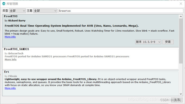
2. Arduino FreeRTOS的使用
Arduino FreeRTOS库可运行于Arduino AVR设备,如Uno、Leonardo、Mega等。本篇使用Uno开发板。
首先要包含Arduino FreeRTOS库的头文件。
#include <Arduino_FreeRTOS.h>
我们使用xTaskCreate()函数来创建任务,函数原型为:
xTaskCreate(TaskFunction_t pvTaskCode,const char * const pcName,uint16_t usStackDepth,void * pvParameters,UBaseType_t uxPriority,TaskHandle_t * pxCreatedTask)
创建任务时需要传入6个参数:
pvTaskCode:任务函数。
pcName:任务名称,一般用于调试和追踪。
usStackDepth:任务堆栈,内核在创建任务时将其分配给任务。该值指定堆栈可以容纳的字数,而不是字节数。例如,如果堆栈为32位宽,并且usStackDepth作为100传入,那么将在RAM中分配400字节的堆栈空间(100 * 4字节)。合理使用此项,因为Arduino Uno只有2KB的RAM。
pvParameters:任务输入参数(可以为NULL)。
uxPriority:任务优先级(0是最低优先级)。
pxCreatedTask:可用于向正在创建的任务传递句柄。然后,可以使用此句柄在API调用中引用任务,例如,更改任务优先级或删除任务(可以为NULL)。
本次实验创建两个串口打印任务:
xTaskCreate(TaskPrint1, "Print1", 128, NULL, 1, NULL);
xTaskCreate(TaskPrint2, "Print2", 128, NULL, 2, NULL);
其中任务2有更高的优先级,会首先执行。
创建任务后,使用**vTaskStartScheduler()**函数启动任务调度。
创建任务实现函数。一般结构如下:
void task(void *param)
{
    while(1)
    {
        ....//需要执行的代码
    }
}
大多数代码都需要延迟函数来停止正在运行的任务,但是在RTOS中,不建议使用**Delay()**函数,因为它会停止CPU,因此RTOS也将停止工作。因此,FreeRTOS具有内核API,可以在特定时间内阻止任务:
vTaskDelay(const TickType_t xTicksToDelay)
例如延时1秒:
vTaskDelay(1000 / portTICK_PERIOD_MS)
其中portTICK_PERIOD_MS与实际MCU的时钟频率相关。
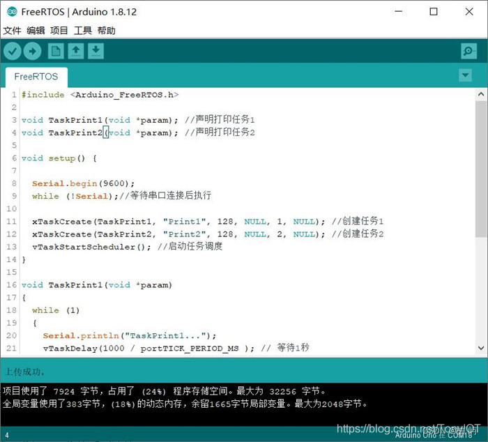
3. 本实验代码如下,拷贝编译下载。
#include <Arduino_FreeRTOS.h>

void TaskPrint1(void *param); //声明打印任务1
void TaskPrint2(void *param); //声明打印任务2

void setup() {

  Serial.begin(9600);
  while (!Serial);//等待串口连接后执行

  xTaskCreate(TaskPrint1, "Print1", 128, NULL, 1, NULL); //创建任务1
  xTaskCreate(TaskPrint2, "Print2", 128, NULL, 2, NULL); //创建任务2
  vTaskStartScheduler(); //启动任务调度
}

void TaskPrint1(void *param)
{
  while (1)
  {
    Serial.println("TaskPrint1...");
    vTaskDelay(1000 / portTICK_PERIOD_MS ); // 等待1秒
  }
}


void TaskPrint2(void *param)
{
  while (1)
  {
    Serial.println("TaskPrint2...");
    vTaskDelay(2000 / portTICK_PERIOD_MS ); // 等待2秒
  }
}

void loop() {

}
4. 实验现象
打开串口监视器,波特兰设置与程序中一致的9600,会看到任务2先运行打印,由于任务1等待1秒,任务2等待2秒,所以每次打印任务1两次,打印任务2一次。
Arduino学习交流群:672088578
更多内容,欢迎关注我的公众号。 微信扫一扫下方二维码即可关注:


 1098
1098


 被折叠的 条评论
为什么被折叠?
被折叠的 条评论
为什么被折叠?
 到【灌水乐园】发言


