


 本文介绍了STM32的ADC转换原理,包括模数转换器的定义、PCM编码过程、模拟信号与数字信号的区别,以及STM32 ADC的常用库函数配置,如初始化、通道配置、软件转换启动和数据读取。同时,提到了STM32F4 ADC的分辨率与精度,并给出了测量结果转化为电压值的方法。最后,建议通过调整可调电阻和ADC获取电压来控制PWM占空比,以实践操作。
一、ADC,模拟数字转换器
1、定义
ADC(Analog to Digital Converter) :模数变换器;简称“模数转换器”,把模拟量转换为数字量的装置。
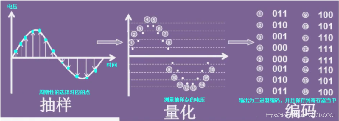
在计算机控制系统中,须经各种检测装置,以连续变化的电压或电流作为模拟量,随时提供被控制对象的有关参数(如速度、压力、温度等)而进行控制。计算机的输入必须是数字量,故需用模数转换器达到控制目的,过程有抽样、量化、编码(PCM编码,脉冲编码调制)。
其次简单介绍一下PCM编码:
(1)抽样:就是对模拟信号进行周期性扫描,把时间上连续的信号变成时间上离散的信号。该模拟信号经过抽样后述应当包含原信号中所有信息,也就是说能无失真的恢复原模拟信号。
(2)量化:就是把经过抽样得到的瞬时值将其幅度离散,即用一组规定的电平,把瞬时抽样值用最接近的电平值来表示,通常是用二进制表示。
(3)编码:就是用一组二进制码组来表示每一个有固定电平的量化值。然而,实际上量化是在编码过程中同时完成的,故编码过程也称为模/数变换,可记作A/D。
2、模拟信号
模拟信号是指用连续变化的物理量表示的信息,其信号的幅度,或频率,或相位随时间作连续变化,如目前广播的声音信号,或图像信号等。抓重点,连续的,如正弦波。
3、数字信号
数字信号指幅度的取值是离散的,幅值表示被限制在有限个数值之内。
二进制码就是一种数字信号。二进制码受噪声的影响小,易于有数字电路进行处理,所以得到了广泛的应用。抓重点,离散的,但在示波器中的方波一般指的是数字信号,把竖线去掉就是离散的了。
4、常用库函数
a.根据ADC_CommonInitTypeDef结构体,初始化ADC外设指定的参数(容易被忽略)
typedef struct
{

  uint32_t ADC_Mode;                      /*!< Configures the ADC to operate in
                                               independent or multi mode.
                                               This parameter can be a value of @ref ADC_Common_mode */
  uint32_t ADC_Prescaler;                 /*!< Select the frequency of the clock
                                               to the ADC. The clock is common for all the ADCs.
                                               This parameter can be a value of @ref ADC_Prescaler */
  uint32_t ADC_DMAAccessMode;             /*!< Configures the Direct memory access
                                              mode for multi ADC mode.
                                               This parameter can be a value of
                                               @ref ADC_Direct_memory_access_mode_for_multi_mode */
  uint32_t ADC_TwoSamplingDelay;          /*!< Configures the Delay between 2 sampling phases.
                                               This parameter can be a value of
                                               @ref ADC_delay_between_2_sampling_phases */

}ADC_CommonInitTypeDef;
- @param ADC_CommonInitStruct: pointer to an ADC_CommonInitTypeDef structure that contains the configuration information for All ADCs peripherals.
void ADC_CommonInit(ADC_CommonInitTypeDef* ADC_CommonInitStruct)
b.根据ADC_InitTypeDef结构体,初始化ADC外设指定的参数
typedef struct
{

  uint32_t ADC_Resolution;                /*!< Configures the ADC resolution dual mode.
                                               This parameter can be a value of @ref ADC_resolution */
  FunctionalState ADC_ScanConvMode;       /*!< Specifies whether the conversion
                                               is performed in Scan (multichannels)
                                               or Single (one channel) mode.
                                               This parameter can be set to ENABLE or DISABLE */
  FunctionalState ADC_ContinuousConvMode; /*!< Specifies whether the conversion
                                               is performed in Continuous or Single mode.
                                               This parameter can be set to ENABLE or DISABLE. */
  uint32_t ADC_ExternalTrigConvEdge;      /*!< Select the external trigger edge and
                                               enable the trigger of a regular group.
                                               This parameter can be a value of
                                               @ref ADC_external_trigger_edge_for_regular_channels_conversion */
  uint32_t ADC_ExternalTrigConv;          /*!< Select the external event used to trigger
                                               the start of conversion of a regular group.
                                               This parameter can be a value of
                                               @ref ADC_extrenal_trigger_sources_for_regular_channels_conversion */
  uint32_t ADC_DataAlign;                 /*!< Specifies whether the ADC data  alignment
                                               is left or right. This parameter can be
                                               a value of @ref ADC_data_align */
  uint8_t  ADC_NbrOfConversion;           /*!< Specifies the number of ADC conversions
                                               that will be done using the sequencer for
                                               regular channel group.
                                               This parameter must range from 1 to 16. */
}ADC_InitTypeDef;
- @brief Initializes the ADCx peripheral according to the specified parameters in the ADC_InitStruct.
- @note This function is used to configure the global features of the ADC ( Resolution and Data Alignment), however, the rest of the configuration
- parameters are specific to the regular channels group (scan mode activation, continuous mode activation, External trigger source and edge, number of conversion in the regular channels group sequencer).
-
@param ADCx: where x can be 1, 2 or 3 to select the ADC peripheral. - @param ADC_InitStruct: pointer to an ADC_InitTypeDef structure that contains the configuration information for the specified ADC peripheral.
void ADC_Init(ADC_TypeDef* ADCx, ADC_InitTypeDef* ADC_InitStruct)
c.为选定的ADC常规通道进行配置
-
@brief Configures for the selected ADC regular channel its corresponding rank in the sequencer and its sample time.
-
@param ADCx: where x can be 1, 2 or 3 to select the ADC peripheral.
-
@param ADC_Channel: the ADC channel to configure.
-
This parameter can be one of the following values:
-
@arg ADC_Channel_0~~~~~~arg ADC_Channel_18 -
@param Rank: The rank in the regular group sequencer.
-
This parameter must be between 1 to 16. -
@param ADC_SampleTime: The sample time value to be set for the selected channel.
-
This parameter can be one of the following values:
-
@arg ADC_SampleTime_3Cycles: Sample time equal to 3 cycles -
@arg ADC_SampleTime_15Cycles: Sample time equal to 15 cycles -
@arg ADC_SampleTime_28Cycles: Sample time equal to 28 cycles -
@arg ADC_SampleTime_56Cycles: Sample time equal to 56 cycles -
@arg ADC_SampleTime_84Cycles: Sample time equal to 84 cycles -
@arg ADC_SampleTime_112Cycles: Sample time equal to 112 cycles -
@arg ADC_SampleTime_144Cycles: Sample time equal to 144 cycles -
@arg ADC_SampleTime_480Cycles: Sample time equal to 480 cycles
void ADC_RegularChannelConfig(ADC_TypeDef* ADCx, uint8_t ADC_Channel, uint8_t Rank, uint8_t ADC_SampleTime)
例如是42MHZ,3cycle采集一次,那么时间就是3*1/42Mhz=0.07us,即三个ADC时钟的时间
d.使能指定的ADC的软件转换启动功能
- @param ADCx: where x
 最低0.47元/天 解锁文章


 被折叠的 条评论
为什么被折叠?
被折叠的 条评论
为什么被折叠?
 到【灌水乐园】发言


