


摘自https://machinerysafety101.com/2017/07/03/safe-drive-control-sto/
Since we are controlling machinery, safety is always a concern. In the 1990’s when I started designing machinery with motor drives, dealing with safety concerns usually meant adding a suitably rated contactor upstream of the drive so that you could interrupt power to the drive in case something went wrong. With early servo drives, interrupting the supply power often meant losing position data or worse. Placing contactors between the drive and the motor solved this problem, but interrupting the supply power would sometimes cause the drive stage of the servo controller to blow up if the switch-off happened with the motor running and under high load. Motor drive manufacturers responded by providing contactors and other components built into their drives, creating a feature called Safe Torque Off (STO).
Note that only Safe Torque Off and Safe Stop 1 can be used for emergency stop functions. Safe Torque Off, Safe Stop 1 and Safe Stop 2 can be used for safety-related stop functions initiated by a safeguarding device. This distinction, between emergency stop functions and safeguarding functions, is an important one.
Safe Torque Off (STO)
According to Siemens, “The STO function ensures that no torque-generating energy can continue to act upon a motor and prevents unintentional starting.” Risk assessment of the machinery can identify the need for an STO function.
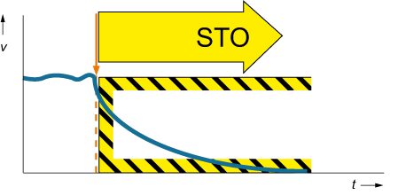
The orange arrow and the dotted line show the initiation of the stopping function.
At the beginning of the stopping process (orange arrow and dotted line), the drive gate pulses are immediately shut off, removing torque from the motor. The speed of the driven equipment will drop at a rate determined by the system friction and inertia until standstill is achieved. Note that it is possible that the driven equipment may coast for some time. You may be able to move the driven equipment by hand or gravity with the drive in the STO mode.
uncontrolled stop
stopping of machine motion by removing electrical power to the machine actuators
NOTE This definition does not imply any other state of other (for example, non-electrical) stopping devices, for example, mechanical or hydraulic brakes that are outside the scope of this standard.
The embodiment of the uncontrolled stop concept is Stop Category 0:
stop category 0 — stopping by immediate removal of power to the machine actuators (i.e., and uncontrolled stop)
Stop category 0 is only appropriate where the machinery has little inertia, or where mechanical friction is high enough that the stopping time is short. It may also be used in cases where the machinery has very high inertia, but only for normal stopping when coasting time is not a factor, not for safety stopping functions where the time to a no-motion state is critical.
Safe Stop 1 (SS1)
If a defined stopping time is needed, a controlled stopping function will be required followed by entry into STO. This stopping function is called “Safe Stop 1” (SS1).
SS1 is directly related to Stop Category 1:
stop category 1 — a controlled stop with power available to the machine actuators to achieve the stop and then removal of power when the stop is achieved;
A “controlled stop” is:
controlled stop
stopping of machine motion with electrical power to the machine actuator maintained during the stopping process
Once the controlled stop is completed, i.e., machine motion has stopped, the drive may then be placed into STO (or category 0 stop):
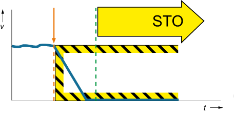
As compared to Fig. 1 where the deceleration curve is gentle and exponential, the active stopping period in Fig. 2 is a linear curve from operating speed to zero speed. At the blue dotted line, the drive enters and stays in STO. This stopping method is typical of many types of machinery, particularly those with servo-driven mechanisms.
Safe Stop 2 (SS2)
In some cases, the risk assessment may show that removing power completely from a mechanism will increase the risk. An example might be a vertical axis where the motor drive is used to maintain the position of the tooling. Removing power from the drive with the tool raised would result in the tooling crashing to the bottom of the axis in an uncontrolled way. Not the desired way to achieve any type of stop!
There are various to prevent this kind of occurrence, but I’m going to limit the discussion here to the Safe Stop 2 function.
stop category 2 — a controlled stop with power left available to the machine actuators.
Emergency Stop functions cannot use Stop Category 2. If you have tooling where Stop Category 2 is the most appropriate stopping function under normal conditions, you will have to add an another means to prevent the axis from falling during the emergency stop. The additional means could be a spring-set brake that is held released by the emergency stop system and is applied when the e‑stop system removes power from the tooling.
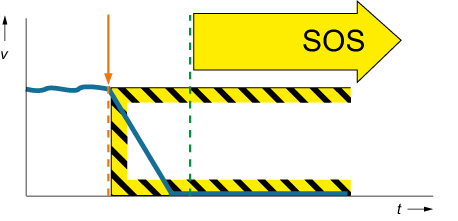
the operation of Safe Stop 2 differs from Safe Stop 1 in that, instead of entering into STO when motion stops, the system enters Safe Operating Stop (SOS) , not STO. SOS is a Stop Category 2 function. Full torque remains available from the motor to hold the tooling in position. Safe standstill is monitored by the drive or other means.
Safe Operating Stop (SOS)
During a safe operating stop (SOS), the motor is brought to a specific position and held there by the drive. Full torque is available to keep the tooling in position. The stop is monitored safely by the drive. 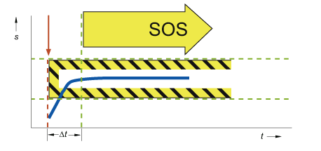
In the figure above, the y‑axis, s, represents the position of the tooling, NOT the velocity, while the x‑axis represents time, t. The start of the position holding function is shown by the orange arrow and dashed line. The period following the green dashed line is the SOS period.
SOS cannot be used for the emergency stop function. Under certain conditions it may be used when guard interlocks are opened, i.e., the guard door on a CNC lathe is opened so that the operator can place a new workpiece.
Safe Standstill
Safe standstill is a condition where motion has stopped and is being monitored by a safety-rated device whose output signals are used to control the release of guard locking devices. Safe standstill is not the same as zero-speed because zero-speed can be achieved without the use of safety-rated control components and design, while safe standstill requires both suitable components and design.
There are various ways to achieve safe standstill. Here are three approaches:
- Rotation sensors
Sensors including proximity sensors, resolvers, and encoders can be used to monitor the motion of the drive components. A safe standstill monitoring device is used to when standstill has occurred. When a machine has an unstable rest position, a proximity sensor should be used to ensure the machine is in a safe condition before the guard locking devices are released. - Back EMF monitoring
Back electromotive force or Back EMF is the voltage created in an electric motor due to the rotation of the armature in the magnetic field in the motor. This voltage opposes the applied voltage and is approximately proportional to the rotational speed of the motor. Back EMF remains after the supply voltage has been removed, allowing monitoring devices to indirectly measure motor speed and standstill. - Failsafe timer
Failsafe timers are time delay relays designed for use in safety functions. Failsafe timers can be used when the stopping performance of the machinery is consistent and known.
Following removal of power from the drive motor, the time delay starts. At the end of the time delay, the relay releases the guard locking devices.
Regular time delay relays cannot be used for this purpose, only fail-safe relays designed to be used in safety functions can be used, along with suitable safety systems design techniques like ISO 13849 or IEC 62061.


 1775
1775


 被折叠的 条评论
为什么被折叠?
被折叠的 条评论
为什么被折叠?
 到【灌水乐园】发言


