


实验五 默认路由和点对点以太网实验
点对点信道互联以太网实验
一、实验目的
(1)验让路由器串行接口配置过程
(2)验证建立PPP链路过程
(3)验证静态路由项配置过程
(4)验证路由表与分组传输路径之回的关系
(5)验证IP分组端到端传输过程
(6)验证不同类型的传输网络将IP分组封装成该传输网络对应的帧格式的过程。
二、实验内容
本实验由路由器 R1 和R2之间用点对点信道互连,路由器R1连接一个网络地址为 192.1.1.0/24 的以太网,路由器 R2连接一个网络地址为 192.1.2.0/24 的以大网,两个以太网上分别连接终端 A 和终端B,完成终端A和终端B之间的数据传输过程。
三、实验步骤
1.AR1220串行接口模块安装界面
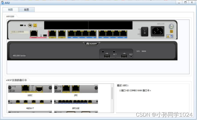
2.完成2SAA模块安装过程后界面

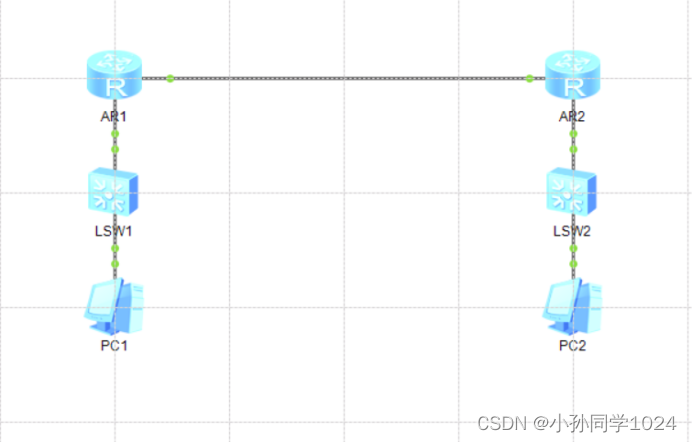
3.完成设备放置和连接后的eHSP界面
4.安装串行总线模块2SA后的ARI接口配置情况

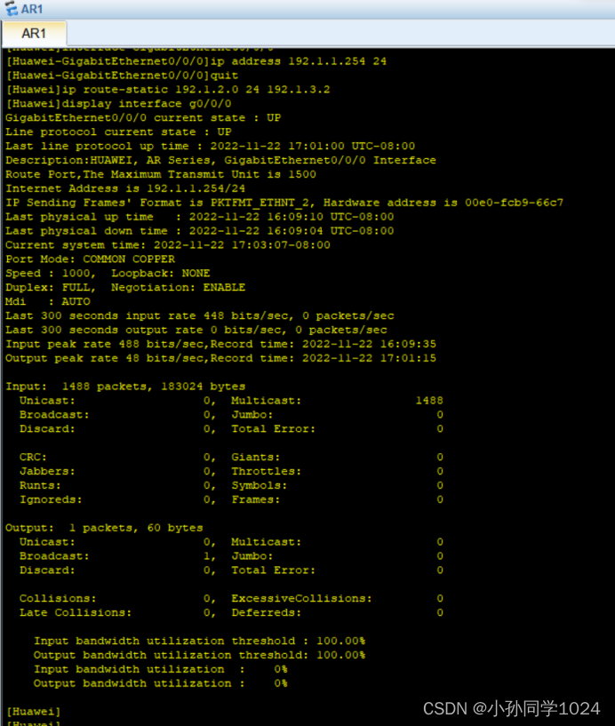
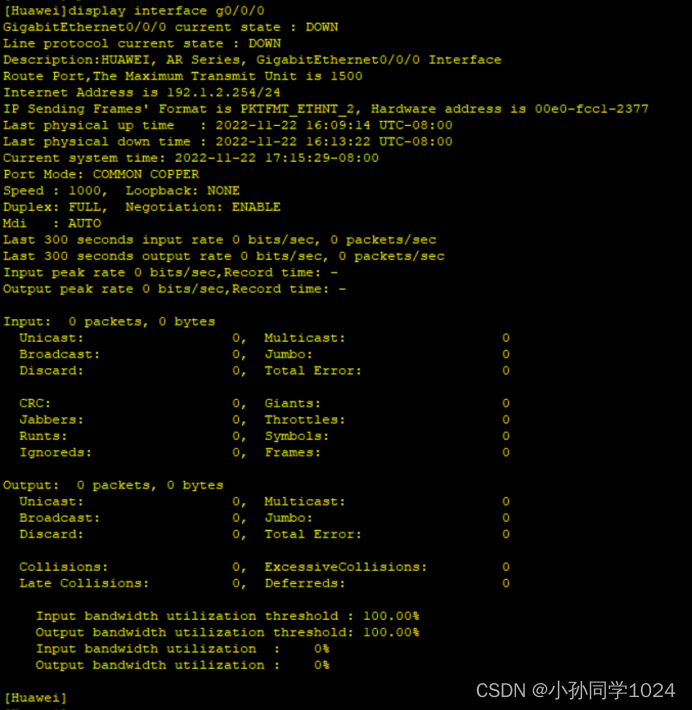
5.AP1千兆以太网接口状态
system-view

undo info-center enable

interface Serial2/0/0

link-protocol ppp

ip address 192.1.3.1 30

quit

aaa

authentication-scheme yyy

authentication-mode local

quit

domain system

authentication-scheme yyy

quit

local-user aaa1 password cipher bbb1

local-user aaa1 service-type ppp

quit

interface Serial2/0/0

ppp authentication-mode chap domain system

ppp chap user aaa2

ppp chap password cipher bbb2

shutdown

undo shutdown

quit

interface GigabitEthernet0/0/0

ip address 192.1.1.254 24

quit

ip route-static 192.1.2.0 24 192.1.3.2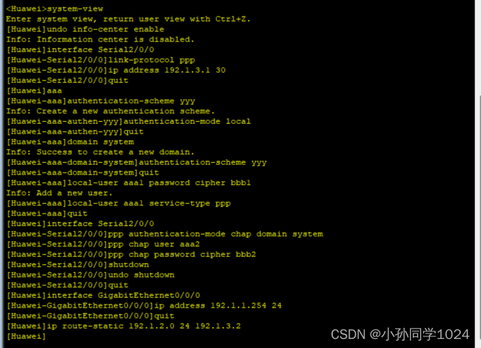
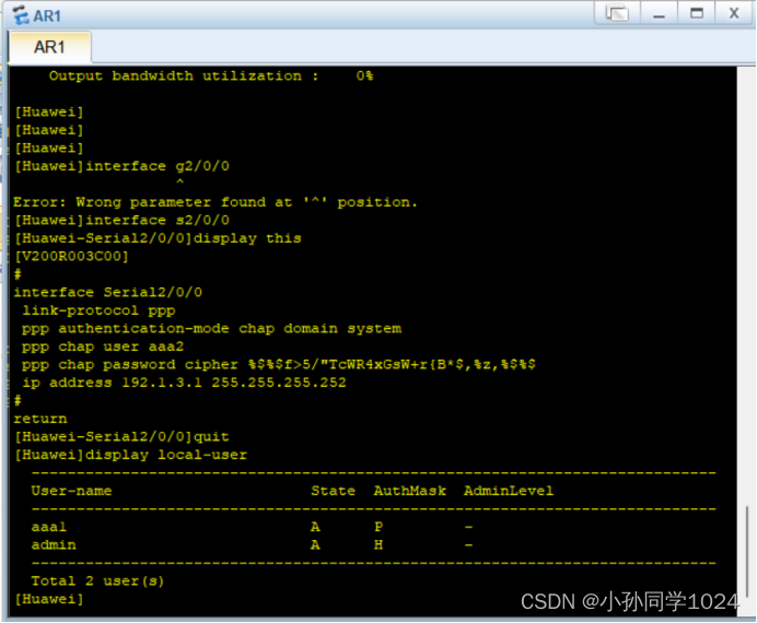
 6.AR1串行接口配置的IP地址、子网掩码、和PPP相关信息
7.AR2千兆以太网接口状态
system-view
undo info-center enable
interface Serial2/0/0
link-protocol ppp
ip address 192.1.3.2 30
quit
aaa
authentication-scheme yyy
authentication-mode local
quit
domain system
authentication-scheme yyy
quit
local-user aaa2 password cipher bbb2
local-user aaa2 service-type ppp
quit
interface Serial2/0/0
ppp authentication-mode chap domain system
ppp chap user aaa1
ppp chap password cipher bbb1
shutdown
undo shutdown
quit
interface GigabitEthernet0/0/0
ip address 192.1.2.254 24
quit
ip route-static 192.1.1.0 24 192.1.3.1 
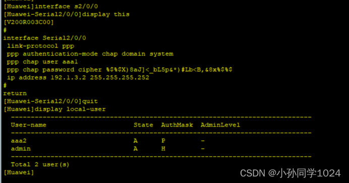
8.AR2串行接口配置的IP地址、子网掩码和PPP相关信息
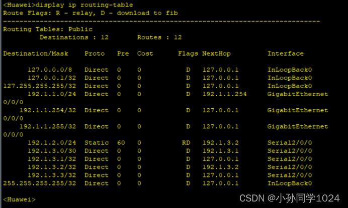
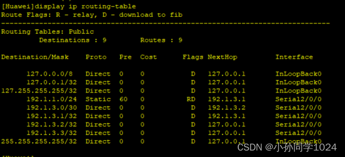
9.AR1的路由表
10.AP2的路由表
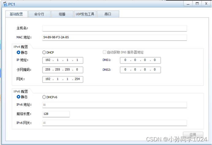
11.PC1配置的IP地址、子网掩码和默认网关地址
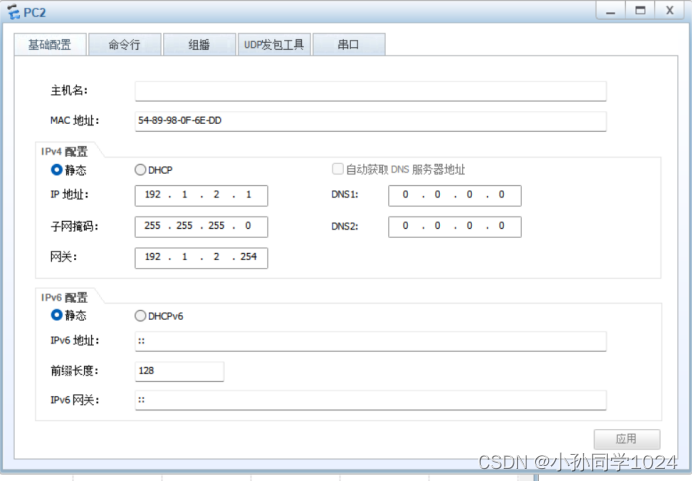
12.PC2配置的IP地址、子网掩码和默认网关地址
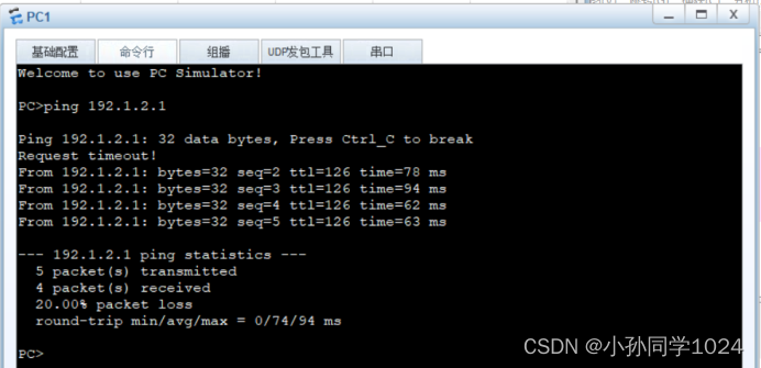
13.PC1和PC2之间的通信过程
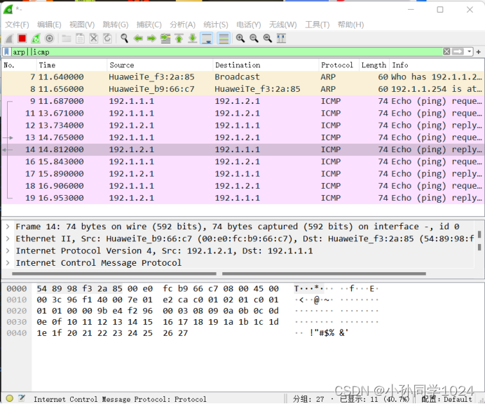
14.在路由器AP1的接口GigabitEthernet0/0/0上捕获的报文序列
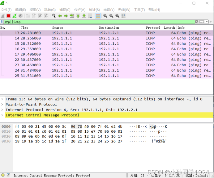
15.在路由器AP1的接口Serial2/0/0上捕获的报文序列
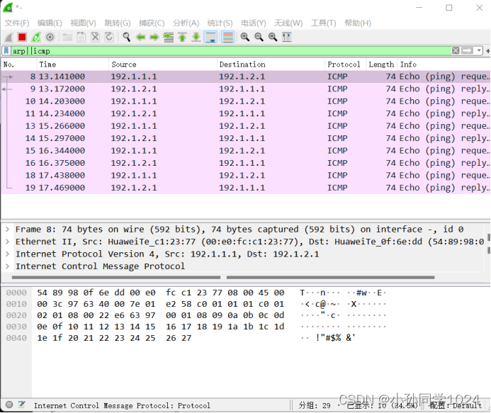
16.在路由器AR2的接口GigabitEthernet0/0/0上捕获的报文序列
默认路由项配置实验
一、实验目的
(1)了解默认路由项的适用环境
(2)掌握默认路由项的配置过程
(3)了解默认路由项可能存在的问题
二、实验内容
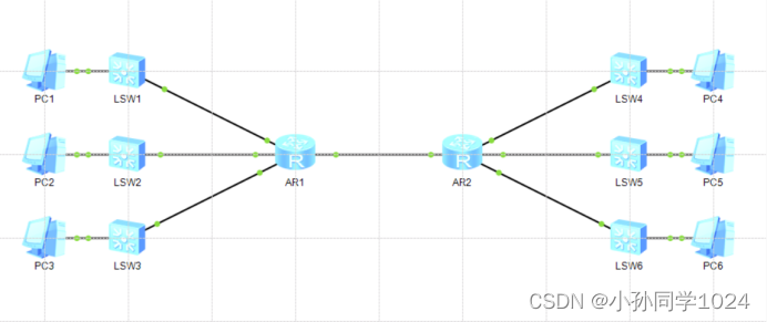
本实验通过在路由器 R1 和R2 中配置默认路由项实现互联以大网中各个终端之间的相互通信过程
三、实验步骤
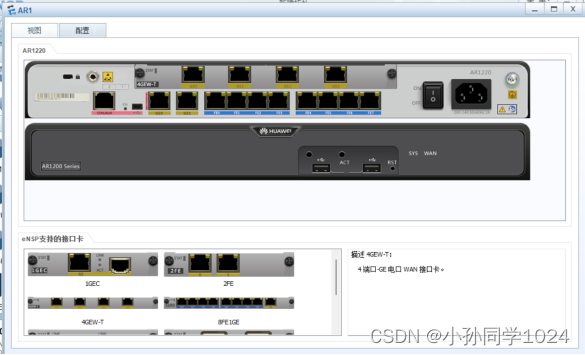
1.安装有4个三层千兆以太网接口的模块4GEW-T后的AR1220
2.完成设配放置和连接后的eNSP界面
3.AR1各个接口配置的IP地址和子网掩码
在AR1 CLI上输入:
system-view
undo info-center enable
interface GigabitEthernet0/0/0
ip address 202.1.7.254 24
quit
interface GigabitEthernet0/0/1
ip address 10.7.3.254 24
quit
interface GigabitEthernet2/0/0
ip address 192.7.3.254 24
quit
interface GigabitEthernet2/0/1
ip address 192.1.3.1 30
quit
ip route-static 0.0.0.0 0 192.1.3.2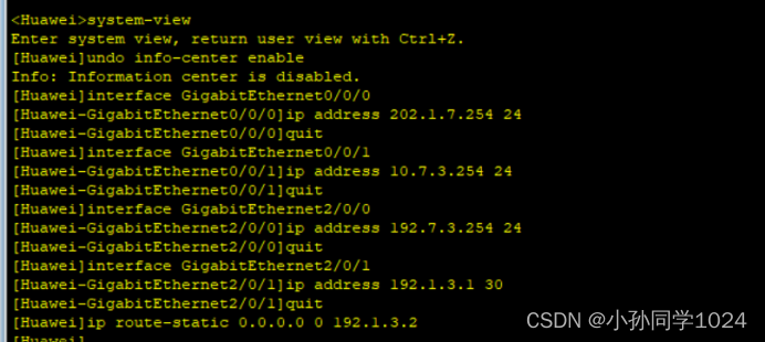
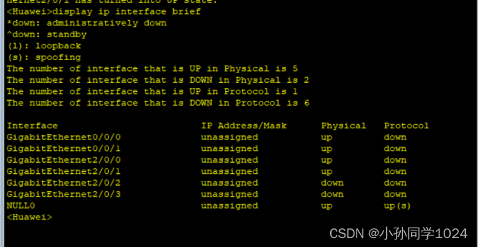
输入:display ip interface brief 查看
4.AR2各个接口配置的IP地址和子网掩码
在AR2 CLI上输入:
system-view
undo info-center enable
interface GigabitEthernet0/0/0
ip address 202.3.6.254 24
quit
interface GigabitEthernet0/0/1
ip address 33.77.6.254 24
quit
interface GigabitEthernet2/0/0
ip address 101.7.3.254 24
quit
interface GigabitEthernet2/0/1
ip address 192.1.3.2 30
quit
ip route-static 0.0.0.0 0 192.1.3.1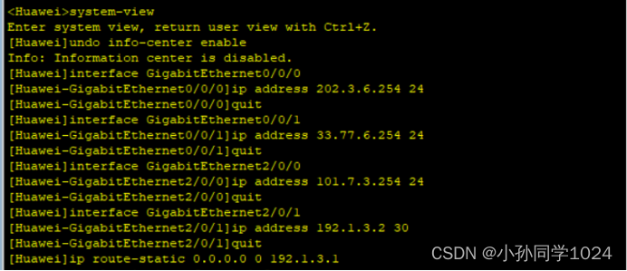
输入:display ip interface brief 查看

5.AR1的路由表
在AR1 CLI中输入:
display ip routing-table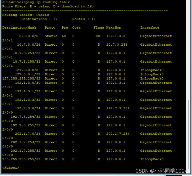
6.AR2的路由表
在AR1 CLI中输入:
display ip routing-table
7.PC1与PC4之间的通信过程

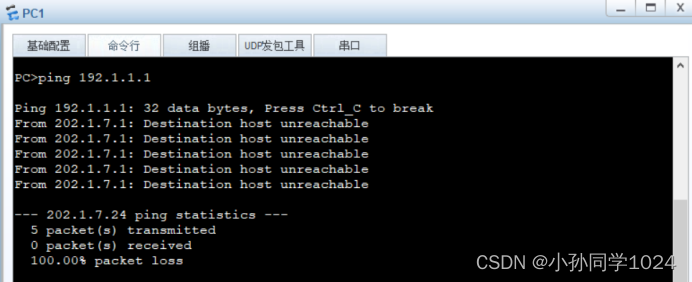
8.PC1对IP 地址192.1.1.1进行ping操作
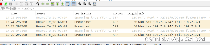
9.AR1连接AR2接口时捕获的报文序列
实验总结
通过本次实验学习了点对点信道通信互联以太网实验和默认路由项配置实验,对路由又有了新的认识和体会。实验过程中会出现接口连接的错误,需要认真分析接口IP地址再进行连接。


 1039
1039

 被折叠的 条评论
为什么被折叠?
被折叠的 条评论
为什么被折叠?
 到【灌水乐园】发言


