


LiteCAD API reference
一、Layer
The user may choose to put certain types of entities on certain layers.Layers can be turned off and on, so that their respective data can be viewed in or out of context with adjacent layers.All new graphic objects are added to the current layer. When you create a new drawing it will already have one layer named “0”.
Adds a new layer into a drawing: HANDLE lcDrwAddLayer (HANDLE hDrw,LPCWSTR szName,LPCWSTR szColor,HANDLE hLinetype,int Linewidth);
Parameters:hDrw(Handle to a drawing object.);szName(Layer name. Must be different from exist layers.);szColor(Layer color.);hLinetype(Handle to a linetype object. NULL for “Continuous” linetype.);Linewidth(Linewidth value.).
二、Linetype
A linetype defines a line’s characteristics. A line can consist of combinations of dashes, dots, spaces and symbols. New entities are added to a drawing using the current linetype. When you create a new drawing it already has linetypes named “ByLayer”, “ByBlock”, and, “Continuous”.
Linetype definition
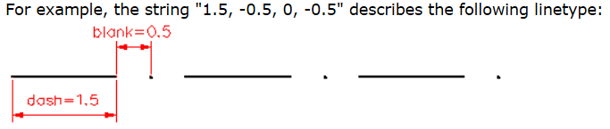
In LiteCAD’s functions the Linetype data is manifested as a plotter-style instruction based upon simple ASCII text
code.Linetypes can have dashes, blank spaces, dots and symbols.Each component of the line’s symbology is delimited by a comma in the text code string. The Dash characteristic is written as a positive number. The blank space characteristic is written as a negative number. A dot characteristic is written as a zero.
Symbol based linetypes (complex linetypes) deviate from the previous definition in their inclusive content. Complex linetypes contain symbols and/or text strings, along with blank spaces, dots, and dashs as desired. Symbol descriptions are enclosed in brackets [ ]. The bracketed description has several components, once again, delimited by commas. The syntax of the info within the brackets are the next:
[char code or name, font file, parameter=value, parameter=value, …]
or
[text, style, parameter=value, parameter=value, …]
All possible parameters are described in the following table:

三、LiteCAD Colors
LiteCAD color can be a true color (24-bit RGB value) or index of a color palette.In objects properties it is represented as a text string. If a text string has 3 digital values (0-255) separated by commas, then color is a true color. If one value (1-255) - index color.On input, index value can be replaced by color name. Litecad recognises the following color names:
“red” (same as “1”)
“yellow” (same as “2”)
“green” (same as “3”)
“cyan” (same as “4”)
“blue” (same as “5”)
“magenta” (same as “6”)
“foreground” (same as “7”)
“gray” (same as “8”)
“ltgray” (same as “9”)
Also, for graphic objects, a special words can be used - “ByLayer” and “ByBlock”.
“ByLayer” means the color assigned to a Layer will dictate the color of an object found on that particular Layer.
“ByBlock” means the color assigned to a Block Reference object will dictate the color of an object added to the Block. If the object is not a part of block but has the “ByBlock” color assigned to it, the foreground color will be used to draw the object.
Foreground color is defined by the LC_PROP_G_COLORFOREM and LC_PROP_G_COLORFOREP property.
Converts color value from string into integer components:BOOL lcColorToVal (LPCWSTR szColor,int pbRGB,int pIndex,int* pRed,int* pGreen,int* pBlue);**
Parameters:
szColor(Color value as string.);pbRGB(Pointer to variable that will receive “RGB” flag of the color.If received value is TRUE, then color is RGB color, if FALSE - index in color palette.);pIndex(Pointer to variable that will receive color index. The received value will be valid only for indexed color (bRGB=FALSE).The index value can be from 0 to 256, where 0 is “ByBlock” and 256 is “ByLayer” colors.);pRed pGreen pBlue(Pointers to variables that will receive Red, Green, Blue values of the color.).
Samples:
lcPropPutStr( hLayer, LC_PROP_LAYER_COLOR, L"200,170,255" );
lcPropPutStr( hEnt, LC_PROP_ENT_COLOR, L"ByLayer" );
lcPropPutStr( hEnt, LC_PROP_ENT_COLOR, L"red" );
lcPropPutStr( hEnt, LC_PROP_ENT_COLOR, L"56" );

WCHAR szColor[32];
int   bRGB, Index, R, G, B;
wcscpy( szColor, lcPropGetStr(hEnt,LC_PROP_ENT_COLOR) );
lcColorToVal( szColor, &bRGB, &Index, &R, &G, &B );
四、Filling
Defines filling style for closed entities.
These are the functions used to manage filling styles in a drawing:lcDrwAddFilling(Adds a new filling style into a drawing);lcFillSetLine(Defines hatch line).
Create entities with semi-transparent filling
void DemoTranspFill (HANDLE hLcWnd)
{
  HANDLE hDrw, hBlock, hTStyle, hEnt;

  // get a drawing and a block, linked with CAD window
  hDrw = lcPropGetHandle( hLcWnd, LC_PROP_WND_DRW );
  hBlock = lcPropGetHandle( hLcWnd, LC_PROP_WND_BLOCK );

  // get active text style
  hTStyle = lcPropGetHandle( hDrw, LC_PROP_DRW_TEXTSTYLE );
  // set font "Arial"
  lcPropPutStr( hTStyle, LC_PROP_TSTYLE_FONT, L"Arial" );
  lcPropPutBool( hTStyle, LC_PROP_TSTYLE_SOLID, true );

  // add bottom text (yellow)
  hEnt = lcBlockAddText2( hBlock, L"0123456789", 15.8, 36.9, LC_TA_CENTER, 5.0, 1.0, 45*LC_DEG_TO_RAD, false );
  lcPropPutStr( hEnt, LC_PROP_ENT_COLOR, L"255,255,0" );

  // add red rectangle
  hEnt = lcBlockAddRect( hBlock, 7,38, 30,20, 0, true );
  lcPropPutStr( hEnt, LC_PROP_ENT_FCOLOR, L"255,0,0" );
  lcPropPutInt( hEnt, LC_PROP_ENT_FALPHA, 120 );

  // add green circle
  hEnt = lcBlockAddCircle( hBlock, 20,33, 10, true );
  lcPropPutStr( hEnt, LC_PROP_ENT_FCOLOR, L"0,255,0" );
  lcPropPutInt( hEnt, LC_PROP_ENT_FALPHA, 120 );

  // add blue polygon
  hEnt = lcBlockAddPolyline( hBlock, 0, true, true );
  lcPlineAddVer( hEnt, 0,  0,34 );
  lcPlineAddVer( hEnt, 0,  8,54 );
  lcPlineAddVer( hEnt, 0, 20,56 );
  lcPlineAddVer( hEnt, 0, 39,40 );
  lcPlineEnd( hEnt );
  lcPropPutStr( hEnt, LC_PROP_ENT_FCOLOR, L"0,0,255" );
  lcPropPutInt( hEnt, LC_PROP_ENT_FALPHA, 120 );

  // update view
  lcBlockUpdate( hBlock, LC_TRUE, 0 );
  // zoom extents
  lcWndZoomRect( hLcWnd, 0, 0, 0, 0 );
}

五、Drawing object(Drawing database)
The LiteCAD drawing object is the internal database representing a drawing. The database contains graphical objects (entities) and non-graphical (named objects). You must create at least one instance of a drawing object in your application. You can load a file into a drawing object or create a drawing programmatically. To view and interactively edit a drawing, an application must link it with a LiteCAD design window.
When you are finished working with a drawing object you must delete its handle to free system memory allocated to it.
Some functions used to manage LiteCAD drawing object:

六、Entities (graphic objects)
Entities are visible graphical objects (lines, circles, raster images, and so on) that make up a drawing. Graphical objects have typical properties such as Identifier, Layer, Linetype, Color, etc. They also have specific properties, depending on their object type, such as, Center, Radius, and Area.

以往的文章已经介绍了所有的命名对象(named objects)和大部分图形对象(graphical objects),下面是剩下还没介绍过的图形对象。
1.Shape
A shape is a group of simple entities that acts as a single entity. There are types of entities that can be grouped into a shape:Line, Polyline, Rectangle,Circle, Arc, Ellipse.
In order a shape can be filled, all grouped entities must make closed contours.
To add a shape into a drawing use following functions:lcBlockBeginShape(Indicates start of shape definition);lcBlockAddShape(Makes a shape from entities added into a block after lcBlockBeginShape function).
Create a shape entity
void DemoShape (HANDLE hLcWnd)
{
  HANDLE hBlock, hEnt;
  // get a block, linked with CAD window
  hBlock = lcPropGetHandle( hLcWnd, LC_PROP_WND_BLOCK );
  // begin Shape entity
  lcBlockBeginShape( hBlock );
  // create entities that will be parts of Shape entity
  lcBlockAddCircle( hBlock, 10, 10, 5, false );
  lcBlockAddCircle( hBlock, 30, 10, 5, false );
  lcBlockAddRect2( hBlock, 0, 0, 40, 20, 5, false );
  // add Shape entity
  hEnt = lcBlockAddShape( hBlock );
  // set solid filling
  lcPropPutBool( hEnt, LC_PROP_ENT_SOLIDFILL, true );
  lcPropPutStr( hEnt, LC_PROP_ENT_FCOLOR, L"0,255,255" );
  // update view
  lcBlockUpdate( hBlock, true, 0 );
  lcWndZoomRect( hLcWnd, -10, -10, 50, 30 );
}

Create a shape entity
void DemoShape3 (HANDLE hLcWnd)
{
  HANDLE hBlock, hEnt;
  double X, Y, X1, X2, Xc, Y1, Y2, Yc, H, R1, R2, R3, dd;

  // get a block, linked with CAD window
  hBlock = lcPropGetHandle( hLcWnd, LC_PROP_WND_BLOCK );
  // begin Shape entity
  lcBlockBeginShape( hBlock );

  // create entities that will be parts of Shape entity
  X1 = 90;
  X2 = 260;
  Y1 = 0;
  Y2 = 180;
  Yc = (Y2 + Y1) / 2.0;
  H = Y2 - Y1;
  R1 = H / 2.0;
  R2 = H / 4.0;
  R3 = (R1 - R2) / 5.0;

  // Fig 1 outside
  lcBlockAddArc( hBlock, X1, Yc, R1, LC_DEG90, LC_DEG180 );
  lcBlockAddLine( hBlock, X1, Y1, X2, Y1 );
  lcBlockAddArc( hBlock, X2, Yc, R1, LC_DEG270, LC_DEG180 );
  lcBlockAddLine( hBlock, X2, Y2, X1, Y2 );

  // Fig 2 inside 1
  lcBlockAddArc(hBlock, X1, Yc, R2, LC_DEG90, LC_DEG180 );
  lcBlockAddLine(hBlock, X1, Yc-R2, X2, Yc-R2 );
  lcBlockAddArc(hBlock, X2, Yc, R2, LC_DEG270, LC_DEG180);
  lcBlockAddLine(hBlock, X2, Yc+R2, X1, Yc+R2);

  // circles inside of 1-2
  dd = (R1 + R2) / 2.0;
  Xc = (X1 + X2) / 2.0;
  X = X1 - dd;
  lcBlockAddCircle( hBlock, X, Yc, R3, false );
  X = X2 + dd;
  lcBlockAddCircle( hBlock, X, Yc, R3, false );
  Y = Yc - dd;
  lcBlockAddCircle( hBlock, X1, Y, R3, false );
  lcBlockAddCircle( hBlock, Xc, Y, R3, false );
  lcBlockAddCircle( hBlock, X2, Y, R3, false );
  Y = Yc + dd;
  lcBlockAddCircle( hBlock, X1, Y, R3, false );
  lcBlockAddCircle( hBlock, Xc, Y, R3, false );
  lcBlockAddCircle( hBlock, X2, Y, R3, false );

  // add Shape entity
  hEnt = lcBlockAddShape( hBlock );
  // set solid filling
  lcPropPutBool( hEnt, LC_PROP_ENT_SOLIDFILL, true );
  lcPropPutStr( hEnt, LC_PROP_ENT_FCOLOR, L"0,255,0" );
  // disable border line
  lcPropPutInt( hEnt, LC_PROP_ENT_LWIDTH, 0 );
  // undate view
  lcBlockUpdate( hBlock, true, 0 );
  lcWndZoomRect( hLcWnd, 0, 0, 0, 0 );
}

lcBlockAddShapeSel(Makes a shape from selected entities);
In order to create Shape from selected entities, use command LC_CMD_SHAPE
Create a shape entity from selected entities
void DemoShape5 (HANDLE hLcWnd)
{
  HANDLE hBlock, hShape;

  // get a block, linked with CAD window
  hBlock = lcPropGetHandle( hLcWnd, LC_PROP_WND_BLOCK );
  // make a shape from selected entities
  hShape = lcBlockAddShapeSel( hBlock, true );
  // set solid filling
  lcPropPutBool( hShape, LC_PROP_ENT_SOLIDFILL, true );
  lcPropPutStr( hShape, LC_PROP_ENT_FCOLOR, L"0,255,0" );
  // disable border line
  lcPropPutInt( hShape, LC_PROP_ENT_LWIDTH, 0 );
  // redraw view
  lcWndRedraw( hLcWnd );
}
lcShapeAddEnt(Adds an entity into a shape);lcShapeEnd(Updates a shape after adding entities).
Create a shape entity from marked entities
void DemoShape6 (HANDLE hLcWnd)
{
  HANDLE hBlock, hShape, hEnt;

  // get a block, linked with CAD window
  hBlock = lcPropGetHandle( hLcWnd, LC_PROP_WND_BLOCK );
  // add Shape entity
  hShape = lcBlockAddShape( hBlock );
  hEnt = lcBlockGetEntByKey( hBlock, 1 );
  if (hEnt){
    lcShapeAddEnt( hShape, hEnt, true );
  }
  hEnt = lcBlockGetEntByKey( hBlock, 2 );
  if (hEnt){
    lcShapeAddEnt( hShape, hEnt, true );
  }
  hEnt = lcBlockGetEntByKey( hBlock, 3 );
  if (hEnt){
    lcShapeAddEnt( hShape, hEnt, true );
  }
  lcShapeEnd( hShape );

  // set solid filling
  lcPropPutBool( hShape, LC_PROP_ENT_SOLIDFILL, true );
  lcPropPutStr( hShape, LC_PROP_ENT_FCOLOR, L"0,255,0" );
  // disable border line
  lcPropPutInt( hShape, LC_PROP_ENT_LWIDTH, 0 );
  // redraw view
  lcWndRedraw( hLcWnd );
}
Enumerate entities which make a shape.
User selects shape entity, then calls this function:
void DemoShapeGetEnts (HANDLE hLcWnd)
{
  HANDLE hBlock, hShape, hEnt, hVer, hPnt;
  int    EntType;
  double X, Y;

  // get the block linked with graphics window
  hBlock = lcPropGetHandle( hLcWnd, LC_PROP_WND_VIEWBLOCK );
  // get selected entity
  hShape = lcBlockGetFirstSel( hBlock );
  if (hShape){
    EntType = lcPropGetInt( hShape, LC_PROP_ENT_TYPE );
    if (EntType == LC_ENT_SHAPE){
      // get first entity of the shape
      hEnt = lcShapeGetFirstEnt( hShape );
      while( hEnt != 0 ){
        EntType = lcPropGetInt( hEnt, LC_PROP_ENT_TYPE );
        if (EntType == LC_ENT_POLYLINE){
          // get first vertex of a polyline
          hVer = lcPlineGetFirstVer( hEnt );
          while( hVer != 0){
            // add a point at polyline vertex
            X = lcPropGetFloat( hVer, LC_PROP_VER_X );
            Y = lcPropGetFloat( hVer, LC_PROP_VER_Y );
            hPnt = lcBlockAddPoint2( hBlock, X, Y, LC_POINT_CIRCLE, -0.75 );
            lcPropPutInt( hPnt, LC_PROP_ENT_COLOR, RGB(100,255,0) );
            // get next vertex of a polyline
            hVer = lcPlineGetNextVer( hEnt, hVer );
          }
        }
        // get next entity of the shape
        hEnt = lcShapeGetNextEnt( hShape, hEnt );
      }
      lcWndRedraw( hLcWnd );
    }
  }
}

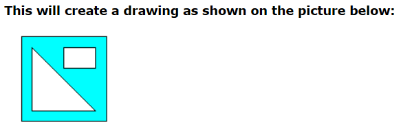
Create a shape entity from polylines
void DemoShapePlines (HANDLE hLcWnd)
{
  HANDLE hBlock, hPline, hShape;

  // get a block, linked with CAD window
  hBlock = lcPropGetHandle( hLcWnd, LC_PROP_WND_BLOCK );
  // begin Shape entity
  lcBlockBeginShape( hBlock );
  // 1st polyline
  hPline = lcBlockAddPolyline( hBlock, 0, true, false );
  lcPlineAddVer( hPline, 0, 10, 10 );
  lcPlineAddVer( hPline, 0, 10, 90 );
  lcPlineAddVer( hPline, 0, 90, 90 );
  lcPlineAddVer( hPline, 0, 90, 10 );
  lcPlineEnd( hPline );
  // 2nd polyline
  hPline = lcBlockAddPolyline( hBlock, 0, true, false );
  lcPlineAddVer( hPline, 0, 20, 20 );
  lcPlineAddVer( hPline, 0, 20, 80 );
  lcPlineAddVer( hPline, 0, 80, 20 );
  lcPlineEnd( hPline );
  // 3rd polyline
  hPline = lcBlockAddPolyline( hBlock, 0, true, false );
  lcPlineAddVer( hPline, 0, 50, 80 );
  lcPlineAddVer( hPline, 0, 80, 80 );
  lcPlineAddVer( hPline, 0, 80, 60 );
  lcPlineAddVer( hPline, 0, 50, 60 );
  lcPlineEnd( hPline );
  // add Shape entity
  hShape = lcBlockAddShape( hBlock );
  // set solid filling
  lcPropPutBool( hShape, LC_PROP_ENT_SOLIDFILL, true );
  lcPropPutStr( hShape, LC_PROP_ENT_FCOLOR, L"0,255,255" );
  // update view
  lcBlockUpdate( hBlock, false, 0 );
  lcWndExeCommand( hLcWnd, LC_CMD_ZOOM_EXT, 0 );
}
Create a shape entity with hatch filling
void DemoShape4 (HANDLE hLcWnd)
{
  HANDLE hDrw, hBlock, hFill, hEnt;
  double Xc, Yc, Size;
  WCHAR* szNameFill = L"Hatch 1";

  // get a drawing and a block, linked with CAD window
  hDrw = lcPropGetHandle( hLcWnd, LC_PROP_WND_DRW );
  hBlock = lcPropGetHandle( hLcWnd, LC_PROP_WND_BLOCK );

  // check if the filling style with specific name already exist
  hFill = lcDrwGetObjectByName( hDrw, LC_OBJ_FILLING, szNameFill );
  if (hFill == 0){
    // don't exist, add it
    hFill = lcDrwAddFilling( hDrw, szNameFill );
    // define the hatch lines
    lcFillSetLine( hFill, 0, 1.0, 45.0*LC_DEG_TO_RAD, 0.5 );
    lcFillSetLine( hFill, 1, 1.0, -45.0*LC_DEG_TO_RAD, 0.5 );
  }

  Xc = 50;
  Yc = 25;
  Size = 20;
  // begin Shape entity
  lcBlockBeginShape( hBlock );
  // Fig 1 outside
  lcBlockAddRect( hBlock, Xc, Yc, Size, Size, 0, false );
  // Fig 2 inside
  lcBlockAddCircle( hBlock, Xc, Yc, Size/4.0, false );
  // add Shape entity
  hEnt = lcBlockAddShape( hBlock );

  // set filling style
  lcPropPutHandle( hEnt, LC_PROP_ENT_FILLING, hFill );

  // undate view
  lcBlockUpdate( hBlock, true, 0 );
  lcWndZoomRect( hLcWnd, Xc-Size, Yc-Size, Xc+Size, Yc+Size );
}

2.Windows Text (single-line)
Create Windows-rendered text
This code sample demonstrates difference of rendering two text types - LC_ENT_TEXT and LC_ENT_TEXTWIN.
// Mode variants:
// 0 - add new text style
// 1 - modify "Standard" text style
//-----------------------------------------------
void DemoTextWin (HANDLE hLcWnd, int Mode)
{
  HANDLE hDrw, hBlock, hTStyle;
  int    Align;
  double X, Y, H, WScale, Angle, Oblique;
  WCHAR* szText = L"Hello World!";
  WCHAR* szStyleName = L"My TextStyle";

  // get drawing and block, linked with CAD window
  hDrw = lcPropGetHandle( hLcWnd, LC_PROP_WND_DRW );
  hBlock = lcPropGetHandle( hLcWnd, LC_PROP_WND_BLOCK );

  if (Mode == 0){
    // get text style with specified name
    hTStyle = lcDrwGetObjectByName( hDrw, LC_OBJ_TEXTSTYLE, szStyleName );
    if (hTStyle == NULL){
      // the style don't exist, create new text style
      hTStyle = lcDrwAddTextStyle( hDrw, szStyleName, L"Times New Roman", true );
    }
  }else{
    // set font "Arial" for the text style "Standard"
    hTStyle = lcPropGetHandle( hDrw, LC_PROP_DRW_TEXTSTYLE_STD );
    lcPropPutBool( hTStyle, LC_PROP_TSTYLE_WINFONT, true );
    lcPropPutStr( hTStyle, LC_PROP_TSTYLE_FONT, L"Arial" );
    lcPropPutBool( hTStyle, LC_PROP_TSTYLE_SOLID, true );
  }
  // make this text style active
  lcPropPutHandle( hDrw, LC_PROP_DRW_TEXTSTYLE, hTStyle );

  Align = LC_TA_CENBOT;  // center-bottom
  X = 0.0;
  Y = 0.0;
  H = 5.0;
  Oblique = 0.0;
  WScale = 1.0;
  Angle = 0.0;
  lcBlockAddText2( hBlock, szText, X, Y, Align, H, WScale, Angle, Oblique );
  Y = Y + (H * 1.5);
  lcBlockAddTextWin2( hBlock, szText, X, Y, Align, H, WScale, Angle, Oblique );

  // update view
  lcBlockUpdate( hBlock, true, 0 );
  lcWndExeCommand( hLcWnd, LC_CMD_ZOOM_EXT, 0 );
}

3.3D Face
To add 3D face object into a drawing use following functions:
lcBlockAddFace(By 3 points)
lcBlockAddFace4(By 4 points)
4.Clipping rectangles
Clipping rectangles are used to clip rectangular parts of main drawing (Model space).
The part can be saved as a bitmap or a file.
There are functions:

LC_CMD_CLIPRECTS - Command to call dialog “Clipping Rectangles”
5.Some graphic objects functions
HANDLE lcEntSplit (HANDLE hEntity,int nParts,BOOL bSelectNew,BOOL bDeleteEnt);
Parameters:
hEntity(Handle to a graphic object to be splitted.);nParts(A number of split parts. The value range is 2…1000.);bSelectNew(If TRUE then the derived entities will be added into selection set.);bDeleteEnt(If TRUE then the source entity will be deleted.).
Split entities
void DemoSplit (HANDLE hLcWnd)
{
  HANDLE hBlock, hCirc, hArc, hEnt, hEntNext;
  int    EntType, i, nArcs;
  double Xc, Yc, Xm, Ym, X2, Y2, Ang;
  bool   bSplit = true;

  // get a block, linked with CAD window
  hBlock = lcPropGetHandle( hLcWnd, LC_PROP_WND_VIEWBLOCK );
  // add 1st circle
  lcBlockAddCircle( hBlock, 0,0, 10, false );
  // add 2nd circle
  hCirc = lcBlockAddCircle( hBlock, 30,30, 10, false );
  lcPropPutFloat( hCirc, LC_PROP_CIRCLE_ANG0, 270 * LC_DEG_TO_RAD );
  lcPropPutBool( hCirc, LC_PROP_CIRCLE_DIRCW, true );
  // add 3rd circle
  hCirc = lcBlockAddCircle( hBlock, 60,0, 10, false );
  lcPropPutFloat( hCirc, LC_PROP_CIRCLE_ANG0, 180 * LC_DEG_TO_RAD );

  if (bSplit){
    nArcs = 4;  // number of arcs instead of a circle
    // split all circles on several arcs and offset the arcs
    hEnt = lcBlockGetFirstEnt( hBlock );
    while( hEnt ){
      // get next entity here, because lcEntSplit will insert
      // new entities instead of hEnt
      hEntNext = lcBlockGetNextEnt( hBlock, hEnt );

      EntType = lcPropGetInt( hEnt, LC_PROP_ENT_TYPE );
      if (EntType == LC_ENT_CIRCLE){
        hArc = lcEntSplit( hEnt, nArcs, false, true );
        if (hArc){
          for (i=0; i<nArcs; ++i){
            // get arc's center point
            Xc = lcPropGetFloat( hArc, LC_PROP_ARC_X );
            Yc = lcPropGetFloat( hArc, LC_PROP_ARC_Y );
            // get arc's middle point
            Xm = lcPropGetFloat( hArc, LC_PROP_ARC_XMID );
            Ym = lcPropGetFloat( hArc, LC_PROP_ARC_YMID );
            // offset arc's center
            lcGetPolarPrm( Xc, Yc, Xm, Ym, &Ang, 0 );
            lcGetPolarPoint( Xc, Yc, Ang, 5.0, &X2, &Y2 );
            lcPropPutFloat( hArc, LC_PROP_ARC_X, X2 );
            lcPropPutFloat( hArc, LC_PROP_ARC_Y, Y2 );
            lcEntUpdate( hArc );
            // get next arc
            hArc = lcBlockGetNextEnt( hBlock, hArc );
          }
        }
      }

      // go to next entuty
      hEnt = hEntNext;
    }
  }
  // display jump lines
  lcPropPutBool( hLcWnd, LC_PROP_WND_JUMPLINES, true );
  // update view
  lcBlockUpdate( hBlock, false, 0 );
  lcWndZoomRect( hLcWnd, -20, -20, 80, 50 );
}

HANDLE lcEntBreak (HANDLE hEntity,double X,double Y,double Delta,BOOL bSelectNew,BOOL bDeleteEnt);
Divides entity on 2 parts at specified point.
The function can be applied to the following entity types: Line, Polyline, Arc .
Parameters:
hEntity(Handle to a graphic object to be splitted.);X Y(A point placed near entity outline. );Delta(Maximum allowed distance between entity outline and the point.);bSelectNew(If TRUE then the derived entities will be added into selection set.);bDeleteEnt(If TRUE then the source entity will be deleted.).
Break entities
void DemoBreak (HANDLE hLcWnd)
{
  HANDLE hBlock, hEnt, hEnt2;
  double X, Y, Delta;
  int    iCol;

  // get a block, linked with CAD window
  hBlock = lcPropGetHandle( hLcWnd, LC_PROP_WND_VIEWBLOCK );

  hEnt = lcBlockGetFirstSel( hBlock );
  if (hEnt){
    Delta = lcPropGetFloat( hLcWnd, LC_PROP_WND_PICKBOXSIZE );
    X = lcPropGetFloat( hLcWnd, LC_PROP_WND_CURSORX );
    Y = lcPropGetFloat( hLcWnd, LC_PROP_WND_CURSORY );
    hEnt2 = lcEntBreak( hEnt, X, Y, Delta, false, true );
    if (hEnt2){
      iCol = 20;
      while( hEnt2 ){
        lcPropPutInt( hEnt2, LC_PROP_ENT_COLORI, iCol );
        iCol+=7;
        hEnt2 = lcBlockGetNextEnt( hBlock, hEnt2 );
      }
      lcBlockUpdate( hBlock, true, 0 );
      lcWndRedraw( hLcWnd );
    }
  }
}
Creates concentric circles, parallel lines, and parallel curves.
The function can be applied to the following entity types: Line, Xline, Polyline, Arc, Circle,Ellipse,Rectangle.
BOOL lcEntOffset (HANDLE hEntity,double Dist);
Parameters:
hEntity(Handle to a graphic object.);Dist(Offset distance. For circle, arc, ellipse, rectangle, negative value means offset
to center side, positive - outside.For other objects negative value means left side, positive - right side (relative to the object direction).).
**BOOL lcEntAlign (HANDLE hEntity,int Alignment,double Xref,double Yref);**Moves a graphic object to a reference coordinate according alignment type.
Parameters:
hEntity(Handle to a graphic object.);
Alignment(Alignment type. Can be one of the following values):
 Xref Yref(Reference point.).
Align entities
void DemoEntAlign (HANDLE hLcWnd)
{
  HANDLE hBlock, hEnt;
  int    Align, EntType;
  double X, Y;

  // get a block, linked with CAD window
  hBlock = lcPropGetHandle( hLcWnd, LC_PROP_WND_VIEWBLOCK );

  X = 50.0;
  Y = 30.0;
  Align = LC_EA_TOP;
//  Align = LC_EA_RIGHT;
//  Align = LC_EA_CENTER;
  hEnt = lcBlockGetFirstEnt( hBlock );
  while( hEnt ){
    EntType = lcPropGetInt( hEnt, LC_PROP_ENT_TYPE );
    if (EntType == LC_ENT_CIRCLE){
      lcEntAlign( hEnt, Align, X, Y );
    }
    hEnt = lcBlockGetNextEnt( hBlock, hEnt );
  }
  lcBlockUpdate( hBlock, true, 0 );
  lcWndRedraw( hLcWnd );
}


Retrieves a point on a entity outline by distance from beginning.
The function works with the following entity types: Line, Polyline, Arc, Circle.BOOL lcEntGetPoint (HANDLE hEnt,double Dist,double pX,double pY,double* pAngle);**
Parameters:
hEnt(Handle to an entity.);Dist(Distance from beginning.);pX pY(Pointers to variables that will receive the found point coordinates.);pAngle(Pointer to variable that will receive tangent angle at the found point.).
Retrieve positions on a polyline by given distance from beginning.
void DemoEntDist (HANDLE hLcWnd)
{
  HANDLE hBlock, hEnt, hLine;
  int    nParts, i;
  double Len, Delta, Dist, X, Y, Angle, TickLen;
  double X1, Y1, X2, Y2;

  nParts = 10;
  TickLen = 0.5;
  // get a block, linked with CAD window
  hBlock = lcPropGetHandle( hLcWnd, LC_PROP_WND_BLOCK );
  // get selected entity
  hEnt = lcBlockGetFirstSel( hBlock );
  if (hEnt){
    // get entity length
    Len = lcPropGetFloat( hEnt, LC_PROP_ENT_LEN );
    if (Len > 0.0){
      Delta = Len / nParts;
      Dist = 0.0;
      // add tick lines at division points
      for (i=0; i<=nParts; ++i){
        if (lcEntGetPoint( hEnt, Dist, &X, &Y, &Angle )){
          lcGetPolarPoint( X, Y, Angle+LC_DEG90, TickLen, &X1, &Y1 );
          lcGetPolarPoint( X, Y, Angle-LC_DEG90, TickLen, &X2, &Y2 );
          hLine = lcBlockAddLine( hBlock, X1, Y1, X2, Y2 );
          lcPropPutInt( hLine, LC_PROP_ENT_COLOR, RGB(255,255,0) );
          Dist += Delta;
        }
      }
      lcBlockUpdate( hBlock, true, 0 );
      lcWndRedraw( hLcWnd );
    }
  }
}
Searches intersection points of 2 graphic objects. The object types can be the following:Line, Construction line, Polyline, Rectangle, Circle, Arc, Ellipse. int lcIntersection (HANDLE hEnt,HANDLE hEnt2);
Remarks:
This function stores found intersection points in inner buffer. Retrieve points from the buffer by subsequent call of the
lcInterGetPoint function.
Find the intersection points of objects
Legend:
- a drawing has a set of relief isolines on layer “Isolines”,
- a section line are placed on layer “0” and has a key “123” (in order to locate the line)
- we find points of intersection of the line with isolines
- at place of intersection points we will add a Point entity and Text entity.
The Text entity is unscalable, i.e. has constant size on a screen when a drawing is being scaled.
void DemoIntersect (HANDLE hLcWnd)
{
  HANDLE hDrw, hBlock, hEnt, hEnt2, hLayer, hLayer2, hTStyle, hPtStyle, hPnt, hLabel;
  int    i, j, n;
  double x, y;
  WCHAR  szNum[16];
  WCHAR* szColor = L"255,0,0";

  // get drawing and block, linked with CAD window
  hDrw = lcPropGetHandle( hLcWnd, LC_PROP_WND_DRW );
  hBlock = lcPropGetHandle( hLcWnd, LC_PROP_WND_BLOCK );
  // get layer "Isolines"
  hLayer = lcDrwGetObjectByName( hDrw, LC_OBJ_LAYER, L"Isolines" );
  // get textstyle "Labels"
  hTStyle = lcDrwGetObjectByName( hDrw, LC_OBJ_TEXTSTYLE, L"Labels" );
  // get an entity which intersect isolines, it have a key "123"
  hEnt = lcBlockGetEntByKey( hBlock, 123 );
  if (hLayer && hEnt && hTStyle){
    // get current point style
    hPtStyle = lcPropGetHandle( hDrw, LC_PROP_DRW_PNTSTYLE );
    // set points appearance (filled circle)
    lcPropPutInt( hPtStyle, LC_PROP_PSTYLE_PTMODE, LC_POINT_CIRCLE | LC_POINT_FILLED );
    // point size, positive value - drawing's units, negative - nonscalable size
    lcPropPutFloat( hPtStyle, LC_PROP_PSTYLE_PTSIZE, -5.0 );
    // meaning of negative LC_PROP_PSTYLE_PTSIZE: true - pixels; false - % of window height
    lcPropPutBool( 0, LC_PROP_G_PNTPIXSIZE, true );
    // make textstyle "Labels" current, in order to create new text entities with this style
    lcPropPutHandle( hDrw, LC_PROP_DRW_TEXTSTYLE, hTStyle );
    j = 1;
    // enumerate entities
    hEnt2 = lcBlockGetFirstEnt( hBlock );
    while( hEnt2 ){
      // get entity's layer
      hLayer2 = lcPropGetHandle( hEnt2, LC_PROP_ENT_LAYER );
      if (hLayer2 == hLayer){
        // find intersections, the function returns a number of intersection points
        n = lcIntersection( hEnt, hEnt2 );
        if (n > 0){
          for (i=0; i<n; i++){
            lcInterGetPoint( i, &x, &y );
            // add a point to a drawing
            hPnt = lcBlockAddPoint( hBlock, x, y );
            // draw it to red color
            lcPropPutStr( hPnt, LC_PROP_ENT_COLOR, szColor );
            lcPropPutStr( hPnt, LC_PROP_ENT_FCOLOR, szColor );

            // add a label text
            _itow( j++, szNum, 10 );
            // negative height value means pixel size instead of drawing units (to make text unscalable)
            hLabel = lcBlockAddText2( hBlock, szNum, x, y, LC_TA_CENBOT, -1, 0, 0, 0 );
            // set pixels offset from insertion point (only for unscalable text)
            lcPropPutInt( hLabel, LC_PROP_TEXT_DX, 0 );
            lcPropPutInt( hLabel, LC_PROP_TEXT_DY, 5 );
            // set the label's color
            lcPropPutStr( hLabel, LC_PROP_ENT_COLOR, L"cyan" );
          }
        }
      }
      // next entity
      hEnt2 = lcBlockGetNextEnt( hBlock, hEnt2 );
    }
    lcBlockUpdate( hBlock, true, 0 );
    lcWndRedraw( hLcWnd );
  }
}

**int lcExpEntity (HANDLE hEntity,int Flags,BOOL bUnrotate);**Used to retrieve simple polylines of graphic object. This function copies the polylines into inner buffer.Coordinates of the polylines vertices can be retrieved with lcExpGetPline and lcExpGetVertex functions.
**int lcExpGetPline (double Delta);**Selects a polyline for subsequent use of lcExpGetVertex function.
BOOL lcExpGetVertex (double pX,double pY);**Retrieves a vertex coordinates of a polyline selected by lcExpGetPline function.First call of the function retrieves first vertex, next call - next vertex and so on until end vertex.
Retrieve vertices of entity’s outlines (of a circle)
void DemoExpEnt (HANDLE hLcWnd)
{
  HANDLE hBlock, hEnt;
  double X, Y, R, dX;
  int    i, nPlines, nVers, iVer;

  // get a block, linked with CAD window
  hBlock = lcPropGetHandle( hLcWnd, LC_PROP_WND_BLOCK );
  // add a circle entity
  X = 50.0;
  Y = 50.0;
  R = 10.0;
  hEnt = lcBlockAddCircle( hBlock, X,Y, R, false );
  // get vertices of the circle's polyline
  lcPropPutInt( hEnt, LC_PROP_CIRC_RESOL, 16 );
  nPlines = lcExpEntity( hEnt, LC_EXP_OUTLINE, false );
  if (nPlines > 0){
    dX = (R + R) * 1.1;  // offset for new points
    for (i=0; i<nPlines; ++i){
      nVers = lcExpGetPline( 0.0 );
      for (iVer=0; iVer<nVers; ++iVer){
        lcExpGetVertex( &X, &Y );
        // add a point to indicate the vertex
        X = X + dX;
        lcBlockAddPoint2( hBlock, X, Y, LC_POINT_PIXEL|LC_POINT_CIRCLE, -0.5 );
      }
    }
  }
  // set other resolution
  lcPropPutInt( hEnt, LC_PROP_CIRC_RESOL, 32 );
  // get vertices of the circle's polyline
  nPlines = lcExpEntity( hEnt, LC_EXP_OUTLINE, false );
  if (nPlines > 0){
    dX *= 2.0;  // offset for new points
    for (i=0; i<nPlines; ++i){
      nVers = lcExpGetPline( 0.0 );
      for (iVer=0; iVer<nVers; ++iVer){
        lcExpGetVertex( &X, &Y );
        // add a point to indicate the vertex
        X = X + dX;
        lcBlockAddPoint2( hBlock, X, Y, LC_POINT_PIXEL|LC_POINT_CIRCLE, -0.5 );
      }
    }
  }
  // set adaptive resolution for the circle
  lcPropPutInt( hEnt, LC_PROP_CIRC_RESOL, -1 );
  // display
  lcBlockUpdate( hBlock, true, 0 );
  lcWndExeCommand( hLcWnd, LC_CMD_ZOOM_EXT, 0 );
}

Retrieve vertices of entity’s outlines (of a text)
void DemoExpEnt2 (HANDLE hLcWnd)
{
  HANDLE hDrw, hBlock, hTStyle, hEnt;
  double X, Y, H;
  int    i, nPlines, nVers, iVer;
  WCHAR* szText = L&ABC&;
  WCHAR* szFont = L&Arial&;
  WCHAR  szBuf[128];

  // get drawing and block, linked with CAD window
  hDrw = lcPropGetHandle( hLcWnd, LC_PROP_WND_DRW );
  hBlock = lcPropGetHandle( hLcWnd, LC_PROP_WND_BLOCK );

  // get active text style
  hTStyle = lcPropGetHandle( hDrw, LC_PROP_DRW_TEXTSTYLE );
  // get font of the text style
  wcscpy( szBuf, lcPropGetStr( hTStyle, LC_PROP_TSTYLE_FONT ));
  if (wcscmp( szBuf, szFont ) != 0){
    // set specified font for the text style
    lcPropPutStr( hTStyle, LC_PROP_TSTYLE_FONT, szFont );
    lcPropPutBool( hTStyle, LC_PROP_TSTYLE_SOLID, true );
  }

  // add a text entity
  X = 10.0;
  Y = 10.0;
  H = 10.0;
  hEnt = lcBlockAddText2( hBlock, szText, X,Y, LC_TA_LEFBOT, H, 1.0, 0.0, 0.0 );
  lcPropPutInt( hEnt, LC_PROP_ENT_COLOR, RGB(150,255,255) );
  lcPropPutInt( hEnt, LC_PROP_TEXT_RESOL, 3 );
  // set colors for new entities (points)
  lcPropPutInt( hDrw, LC_PROP_DRW_COLORT, RGB(255,0,0) );
  lcPropPutInt( hDrw, LC_PROP_DRW_FCOLORT, RGB(255,0,0) );
  // get vertices of the text's polylines
  nPlines = lcExpEntity( hEnt, LC_EXP_OUTLINE, false );
  if (nPlines > 0){
    for (i=0; i<nPlines; ++i){
      nVers = lcExpGetPline( 0.0 );
      for (iVer=0; iVer<nVers; ++iVer){
        lcExpGetVertex( &X, &Y );
        // add a point to indicate the vertex
        lcBlockAddPoint2( hBlock, X, Y, LC_POINT_CIRCLE|LC_POINT_FILLED, -0.5 );
      }
    }
  }
  // display
  lcBlockUpdate( hBlock, true, 0 );
  lcWndExeCommand( hLcWnd, LC_CMD_ZOOM_EXT, 0 );
}

Retrieve vertices of entity’s hatch lines (barcode)
void DemoBarcHatchAndGetLines (HANDLE hLcWnd)
{
  HANDLE hDrw, hBlock, hFill, hEnt, hEntPline;
  WCHAR* szNameFill = L"Hatch 1";
  WCHAR* szBcText = L"123";
  double X, Y, X2, Y2, W, OffsetX, OffsetY;
  int    nPlines, nVers, i, j, Step;

  // get drawing and block, linked with CAD window
  hDrw = lcPropGetHandle( hLcWnd, LC_PROP_WND_DRW );
  hBlock = lcPropGetHandle( hLcWnd, LC_PROP_WND_VIEWBLOCK );

  // check if the filling style with specific name already exist
  hFill = lcDrwGetObjectByName( hDrw, LC_OBJ_FILLING, szNameFill );
  if (hFill == 0){
    // don't exist, add it
    hFill = lcDrwAddFilling( hDrw, szNameFill );
    lcFillSetLine( hFill, 0, 0.05, 45.0*LC_DEG_TO_RAD, 0.02 );
  }

  // disable solid barcodes
  lcPropPutBool( hDrw, LC_PROP_DRW_BARCSOLID, false );
  // set active color for barcode
  lcPropPutStr( hDrw, LC_PROP_DRW_COLOR, L"ByLayer" );

  // Create QR-code filled with lines
  X = 10;  // center of QR-code
  Y = 10;
  W = 8;   // width and height of QR-code
  hEnt = lcBlockAddBarcode( hBlock, LC_BARTYPE_QR, X, Y, W, 0, szBcText );
  lcPropPutInt( hEnt, LC_PROP_BARC_ECLEVEL, LC_BARC_QRECL_M );
  lcPropPutFloat( hEnt, LC_PROP_BARC_OFFSET, 0.025 );
  lcPropPutHandle( hEnt, LC_PROP_ENT_FILLING, hFill );
  lcEntUpdate( hEnt );

  // set active color for new entities
  lcPropPutStr( hDrw, LC_PROP_DRW_COLOR, L"255,0,0" );

  // extract barcode outlines and hatch lines
  OffsetX = 8.5;
  OffsetY = 0.0;
  for (Step=0; Step<2; ++Step){
    if (Step == 0){
      // hatch lines
      nPlines = lcExpEntity( hEnt, LC_EXP_HATCH, false );
      for (i=0; i<nPlines; ++i){
        nVers = lcExpGetPline( 0.0 );
        if (nVers == 2){
          lcExpGetVertex( &X, &Y );
          X = X + OffsetX;
          Y = Y + OffsetY;
          lcExpGetVertex( &X2, &Y2 );
          X2 = X2 + OffsetX;
          Y2 = Y2 + OffsetY;
          lcBlockAddLine( hBlock, X, Y, X2, Y2 );
        }
      }
    }else{
      // outlines
      OffsetY = -OffsetX;
      OffsetX = 0;
      nPlines = lcExpEntity( hEnt, LC_EXP_OUTLINE, false );
      for (i=0; i<nPlines; ++i){
        hEntPline = lcBlockAddPolyline( hBlock, 0, false, false );
        nVers = lcExpGetPline( 0.0 );
        for (j=0; j<nVers; ++j){
          lcExpGetVertex( &X, &Y );
          X = X + OffsetX;
          Y = Y + OffsetY;
          lcPlineAddVer( hEntPline, 0, X, Y );
        }
        lcPlineEnd( hEntPline );
      }
    }
  }

  // update block
  lcBlockUpdate( hBlock, true, 0 );
  // zoom extents
  lcWndZoomRect( hLcWnd, 0,0,0,0 );
}

七、Extra data
lcEntXData:Allocates extra data buffer inside of entity
BOOL lcEntXData (HANDLE hEntity,int Id,int Flags,int nBytes);
Parameters:
hEntity(Handle to a graphic object.);Id(Application specific identifier of the extra data (entity property LC_PROP_ENT_XDATAID).The value varies from 0 to 10’000);Flags(Application specific flags (entity property LC_PROP_ENT_XDATAFLAGS));nBytes(Size of data buffer, in bytes (entity property LC_PROP_ENT_XDATASIZE)).
Storing extra data in entities
In order to locate the entity with extra data
we use its key value (property LC_PROP_ENT_KEY) .
// sample data structure
struct ENTXDATA {
  int    Num;
  bool   bCW;
  double Weight;
  double Prm[10];
  WCHAR  Name[32];
  int    Year;
};
//-----------------------------------------------
// Save information
//-----------------------------------------------
void DemoEntXDataPut (HANDLE hBlock)
{
  HANDLE   hEnt;
  int      Key, Size, Id, Flags;
  WCHAR*   szText = L"This string is stored in entity";
  ENTXDATA MyData;

  Key = 101;
  hEnt = lcDrwGetEntByKey( hBlock, Key );
  if (hEnt){
    // write text data into the entity
    lcPropPutStr( hEnt, LC_PROP_ENT_XSTR, szText );
  }

  // set fields of 'MyData' structure
  Size = sizeof(ENTXDATA);
  memset( &MyData, 0, Size );
  MyData.Num = 15;
  MyData.bCW = true;
  MyData.Weight = 1000.0;
  MyData.Prm[0] = 5.6;
  MyData.Prm[1] = 7.8;
  MyData.Prm[2] = 9.123;
  wcscpy( MyData.Name, L"Samsung" );
  MyData.Year = 2017;

  Key = 102;
  hEnt = lcDrwGetEntByKey( hBlock, Key );
  if (hEnt){
    // write binary data into the entity
    // allocate memory inside of the entity
    Id = 32;
    Flags = 9002;
    if (lcEntXData( hEnt, Id, Flags, Size )){
      // write 'MyData' contents into the entity
      lcPropPutHandle( hEnt, LC_PROP_ENT_XDATA, &MyData );
    }
  }

  // write binary data into entity using lcXData... functions
  Key = 103;
  hEnt = lcDrwGetEntByKey( hBlock, Key );
  if (hEnt){
    hData = lcXDataBegin();
    lcPropPutBool( hData, LC_PROP_XDATA_BOOL, MyData.bCW );
    lcPropPutInt( hData, LC_PROP_XDATA_INT, MyData.Num );
    lcPropPutFloat( hData, LC_PROP_XDATA_FLOAT, MyData.Weight );
    lcPropPutFloat( hData, LC_PROP_XDATA_FLOAT, MyData.Prm[0] );
    lcPropPutFloat( hData, LC_PROP_XDATA_FLOAT, MyData.Prm[1] );
    lcPropPutFloat( hData, LC_PROP_XDATA_FLOAT, MyData.Prm[2] );
    lcPropPutStr( hData, LC_PROP_XDATA_STR, MyData.Name );
    lcPropPutInt( hData, LC_PROP_XDATA_INT, MyData.Year );
    Size = lcXDataEnd( hData);
    // allocate memory inside of the entity
    Id = 33;
    Flags = 9003;
    if (lcEntXData( hEnt, Id, Flags, Size )){
      // write temporary buffer (hData) into the entity
      lcPropPutHandle( hEnt, LC_PROP_ENT_XDATA, hData );
    }
    // free temporary buffer
    lcXDataClear( hData);
  }
}
//-----------------------------------------------
// Retrieve information
//-----------------------------------------------
void DemoEntXDataGet (HANDLE hBlock)
{
  HANDLE   hEnt;
  int      Key, Size, Size2, Id, Flags;
  BOOL     bXStr;
  WCHAR    szText[256];
  ENTXDATA MyData;

  Key = 101;
  hEnt = lcDrwGetEntByKey( hBlock, Key );
  if (hEnt){
    // retrieve text data from the entity
    // check if XData contains text string
    bXStr = lcPropGetBool( hEnt, LC_PROP_ENT_XSTR );
    if (bXStr){
      // check if the size fits our buffer
      Size = lcPropGetInt( hEnt, LC_PROP_ENT_XDATASIZE );
      if (0<Size && Size<256){
        wcscpy( szText, lcPropGetStr( hEnt, LC_PROP_ENT_XSTR ) );
        // now variable 'szText' contains stored text
      }
    }
  }

  Key = 102;
  hEnt = lcDrwGetEntByKey( hBlock, Key );
  if (hEnt){
    // retrieve binary data from the entity
    Id = lcPropGetInt( hEnt, LC_PROP_ENT_XDATAID );
    Flags = lcPropGetInt( hEnt, LC_PROP_ENT_XDATAFLAGS );
    Size = lcPropGetInt( hEnt, LC_PROP_ENT_XDATASIZE );
    Size2 = sizeof(ENTXDATA);
    if (Size == Size2){
      memcpy( &MyData, lcPropGetHandle( hEnt, LC_PROP_ENT_XDATA ), Size );
      // now variable 'MyData' contains stored data
    }
  }

  // retrieve binary data from entity using lcXDataSet
  Key = 103;
  hEnt = lcDrwGetEntByKey( hBlock, Key );
  if (hEnt){
    Size = sizeof(ENTXDATA);
    memset( &MyData, 0, Size );
    Id = lcPropGetInt( hEnt, LC_PROP_ENT_XDATAID );
    Flags = lcPropGetInt( hEnt, LC_PROP_ENT_XDATAFLAGS );
    Size = lcPropGetInt( hEnt, LC_PROP_ENT_XDATASIZE );
    hData = lcPropGetHandle( hEnt, LC_PROP_ENT_XDATA );
    lcXDataSet( hData );
    // get data
    MyData.bCW = lcPropGetBool( hData, LC_PROP_XDATA_BOOL );
    MyData.Num = lcPropGetInt( hData, LC_PROP_XDATA_INT );
    MyData.Weight = lcPropGetFloat( hData, LC_PROP_XDATA_FLOAT );
    MyData.Prm[0] = lcPropGetFloat( hData, LC_PROP_XDATA_FLOAT );
    MyData.Prm[1] = lcPropGetFloat( hData, LC_PROP_XDATA_FLOAT );
    MyData.Prm[2] = lcPropGetFloat( hData, LC_PROP_XDATA_FLOAT );
    wcscpy( MyData.Name, lcPropGetStr( hData, LC_PROP_XDATA_STR ));
    MyData.Year = lcPropGetInt( hData, LC_PROP_XDATA_INT );
  }
}


 1万+
1万+


 被折叠的 条评论
为什么被折叠?
被折叠的 条评论
为什么被折叠?
 到【灌水乐园】发言


