


LiteCAD API reference
一、Point
The point’s appearance depends on the drawing’s properties
LC_PROP_DRW_PDMODE and LC_PROP_DRW_PDSIZE


To add points into a drawing use following functions:lcBlockAddPoint;lcBlockAddPoint2;lcBlockAddPoint3d
Points buffer
Points buffer is a list of points that represent geometric shape. It can be drawn in a window with the function lcPaint_DrawPtbuf .
二、Construction Line (and Ray)
Lines that extend to infinity in one or both directions, known as rays and construction lines, respectively, can be used as references for creating other objects. For example, you can use construction lines to find the center of a triangle, prepare multiple views of the same item, or create temporary intersections to use for object snaps.

To add construction lines and rays into a drawing use following functions:lcBlockAddXline;lcBlockAddXline2P.
Type specific functions:lcXlinePutDir.
三、Line
A single line segment having two endpoints only. Lines can be one segment or a series of connected segments, but each segment is a separate line object. Use the line object if you want to edit individual segments. If you need to draw a series of line segments as a single object, use the Polyline object.
void DemoTangLines (HANDLE hLcWnd)
{
  HANDLE hDrw, hBlock, hEnt1, hEnt2, hEnt3, hLayer1, hLayer2;
  WCHAR* szName1 = L"Circles";
  WCHAR* szName2 = L"Tangent Lines";

  // get drawing and block, linked with CAD window
  hDrw = lcPropGetHandle( hLcWnd, LC_PROP_WND_DRW );
  hBlock = lcPropGetHandle( hLcWnd, LC_PROP_WND_VIEWBLOCK );
  // layer for circles
  hLayer1 = lcDrwGetObjectByName( hDrw, LC_OBJ_LAYER, szName1 );
  if (hLayer1 == 0){
    // create the layer
    hLayer1 = lcDrwAddLayer( hDrw, szName1, L"foreground", 0, LC_LWIDTH_DEFAULT );
  }
  // layer for lines
  hLayer2 = lcDrwGetObjectByName( hDrw, LC_OBJ_LAYER, szName2 );
  if (hLayer2 == 0){
    // create the layer
    hLayer2 = lcDrwAddLayer( hDrw, szName2, L"255,0,0", 0, LC_LWIDTH_DEFAULT );
  }
  // set active layer
  lcPropPutHandle( hDrw, LC_PROP_DRW_LAYER, hLayer1 );
  // add circles
  hEnt1 = lcBlockAddCircle( hBlock, 0, 0, 10, LC_FALSE );
  hEnt2 = lcBlockAddCircle( hBlock, 20, 20, 15, LC_FALSE );
  hEnt3 = lcBlockAddCircle( hBlock, 28, -10, 7, LC_FALSE );
  // set active layer
  lcPropPutHandle( hDrw, LC_PROP_DRW_LAYER, hLayer2 );
  // add tangent lines
  lcBlockAddLineTan( hBlock, hEnt1, hEnt2, 0 );
  lcBlockAddLineTan( hBlock, hEnt1, hEnt2, 1 );
  lcBlockAddLineTan( hBlock, hEnt1, hEnt3, 2 );
  lcBlockAddLineTan( hBlock, hEnt2, hEnt3, 3 );
  // display
  lcBlockUpdate( hBlock, true, 0 );
  lcWndExeCommand( hLcWnd, LC_CMD_ZOOM_EXT, 0 );
}

四、Angles
In API functions and object properties, angle is specified in radians, counter-clockwise from 0-X axis.
LC_RAD_TO_DEG: 57.2957795130823208 Coefficient for converting radians to degrees.
LC_DEG_TO_RAD: 0.0174532925199433 Coefficient for converting degrees to radians.
五、Polyline
A polyline is a connected sequence of line or arc segments created as a single object. Use polylines if you want to edit all segments at once (although you can also edit them singly). You can apply various Fit types to polylines and close the polyline to form a polygon.
Closed polylines can be filled with solid color. LiteCAD treats such objects as polygons and the user can select them by clicking inside of their boundary(s).
Create polylines
void DemoPolylines (HANDLE hLcWnd)
{
  HANDLE hBlock;
  HANDLE hPline, hPline2, hPline3, hPline4, hPline5;

  // get the block linked to graphics window
  hBlock = lcPropGetHandle( hLcWnd, LC_PROP_WND_VIEWBLOCK );
  // add a polyline object
  hPline = lcBlockAddPolyline( hBlock, 0, false, false );
  lcPlineAddVer( hPline, 0, 10, 0 );
  lcPlineAddVer( hPline, 0, 20, 10 );
  lcPlineAddVer( hPline, 0, 30, 0 );
  lcPlineAddVer( hPline, 0, 40, 10 );
  lcPlineAddVer( hPline, 0, 50, 0 );
  lcPlineAddVer( hPline, 0, 60, 10 );
  lcPlineAddVer( hPline, 0, 70, 0 );
  lcPlineEnd( hPline );
  // copy and move the polyline
  lcBlockSelectEnt( hBlock, hPline, true );
  lcBlockSelMove( hBlock, 0, 20, true, false );
  hPline2 = lcBlockGetLastEnt( hBlock );
  lcBlockSelMove( hBlock, 0, 40, true, false );
  hPline3 = lcBlockGetLastEnt( hBlock );
  lcBlockSelMove( hBlock, 0, 60, true, false );
  hPline4 = lcBlockGetLastEnt( hBlock );
  lcBlockSelMove( hBlock, 0, 80, true, false );
  hPline5 = lcBlockGetLastEnt( hBlock );
  lcBlockUnselect( hBlock );
  // modify fit type of the copied polylines
  lcPropPutInt( hPline2, LC_PROP_PLINE_FIT, LC_PLFIT_QUAD );
  lcPropPutInt( hPline3, LC_PROP_PLINE_FIT, LC_PLFIT_CUBIC );
  lcPropPutInt( hPline4, LC_PROP_PLINE_FIT, LC_PLFIT_SPLINE );
  lcPropPutInt( hPline5, LC_PROP_PLINE_FIT, LC_PLFIT_ROUND );
  lcPropPutFloat( hPline5, LC_PROP_PLINE_RADIUS, 2.5 );

  lcBlockUpdate( hBlock, true, 0 );
  lcWndExeCommand( hLcWnd, LC_CMD_ZOOM_EXT, 0 );
}

Create a closed polylines with filling
void DemoFilling (HANDLE hLcWnd)
{
  HANDLE hDrw, hBlock, hEnt, hEnt2, hFill, hFill2;
  WCHAR* szNameFill = L"Hatch 1";
  WCHAR* szNameFill2 = L"Hatch 2";

  // get a drawing and a block, linked with CAD window
  hDrw = lcPropGetHandle( hLcWnd, LC_PROP_WND_DRW );
  hBlock = lcPropGetHandle( hLcWnd, LC_PROP_WND_BLOCK );

  // check if the filling style with specific name already exist
  hFill = lcDrwGetObjectByName( hDrw, LC_OBJ_FILLING, szNameFill );
  if (hFill == 0){
    // don't exist, add it
    hFill = lcDrwAddFilling( hDrw, szNameFill );
    lcFillSetLine( hFill, 0, 1.0, 0.0, 0.5 );
  }

  // check if the filling style with specific name already exist
  hFill2 = lcDrwGetObjectByName( hDrw, LC_OBJ_FILLING, szNameFill2 );
  if (hFill2 == 0){
    // don't exist, add it
    hFill2 = lcDrwAddFilling( hDrw, szNameFill2 );
    lcFillSetLine( hFill2, 0, 1.8, 45.0*LC_DEG_TO_RAD, 0.5 );
    lcFillSetLine( hFill2, 1, 1.8, -45.0*LC_DEG_TO_RAD, 0.5 );
  }

  // create closed and filled polyline
  // the filling is solid by default
  hEnt = lcBlockAddPolyline( hBlock, LC_PLFIT_NONE, true, true );
  lcPlineAddVer( hEnt, 0, 10,30 );
  lcPlineAddVer( hEnt, 0,  8,55 );
  lcPlineAddVer( hEnt, 0, 30,70 );
  lcPlineAddVer( hEnt, 0, 45,38 );
  lcPlineEnd( hEnt );
  // set filling color (red)
  lcPropPutInt( hEnt, LC_PROP_ENT_FCOLORT, RGB(255,0,0) );

  // copy the polyline
  hEnt2 = lcBlockAddClone( hBlock, hEnt );
  // move the copied polyline
  lcEntMove( hEnt2, 40, -10 );
  // set filling color (green)
  lcPropPutInt( hEnt2, LC_PROP_ENT_COLORT, RGB(0,255,0) );
  // set filling style
  lcPropPutHandle( hEnt2, LC_PROP_ENT_FILLING, hFill );

  // copy the polyline
  hEnt2 = lcBlockAddClone( hBlock, hEnt );
  // move the copied polyline
  lcEntMove( hEnt2, 80, 10 );
  // set filling color (cyan)
  lcPropPutInt( hEnt2, LC_PROP_ENT_COLORT, RGB(0,255,255) );
  // set filling style
  lcPropPutHandle( hEnt2, LC_PROP_ENT_FILLING, hFill2 );

  // update view
  lcBlockUpdate( hBlock, LC_TRUE, 0 );
  // zoom extents
  lcWndZoomRect( hLcWnd, 0, 0, 0, 0 );
}

void DemoRPilygons (HANDLE hLcWnd)
{
  HANDLE hDrw, hBlock;
  double X, Y, R, Ang;

  // get drawing and block, linked with CAD window
  hDrw = lcPropGetHandle( hLcWnd, LC_PROP_WND_DRW );
  hBlock = lcPropGetHandle( hLcWnd, LC_PROP_WND_BLOCK );

  X = 10.0;
  Y = 20.0;
  R = 10.0;
  Ang = 90.0 * LC_DEG_TO_RAD;
  lcPropPutInt( hDrw, LC_PROP_DRW_COLORT, RGB(0,100,200) );
  lcBlockAddCircle( hBlock, X,Y, R, false );
  lcPropPutInt( hDrw, LC_PROP_DRW_COLORT, RGB(255,150,0) );
  lcPropPutInt( hDrw, LC_PROP_DRW_FCOLORT, RGB(20,50,80) );
  lcBlockAddRPolygon( hBlock, 6, X,Y, R, Ang, false, false );
  lcBlockAddRPolygon( hBlock, 3, X,Y, R, Ang, true, true );
  lcBlockUpdate( hBlock, true, 0 );
  lcWndZoomRect( hLcWnd, X-R-R, Y-R-R, X+R+R, Y+R+R );
}

Fit type of polyline
A “Fit type” parameter determines how a polyline’s curve fits to a polyline’s vertices.
LC_PLFIT_BULGE(“Bulge coefficient”);LC_PLFIT_QUAD(Quadratic B-spline);
LC_PLFIT_CUBIC;LC_PLFIT_ROUND;LC_PLFIT_LINQUAD.
Multipolygon
Multipolygon object is a list of polygons. It is used to display filled shapes. It can be drawn in a window with the function lcPaint_DrawMpgon .
六、Rectangle
A rectangle is a quadrilateral shape with four right angles. It can be rotated around its center point.The corners can be smoothed with an arc or chamfer.
To add rectangles into a drawing use following functions:lcBlockAddRect;lcBlockAddRect2.

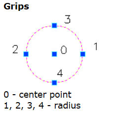
七、Circle
To add circles into a drawing use following functions: HANDLE lcBlockAddCircle ( HANDLE hBlock,double X,double Y,double Radius,BOOL bFilled);
八、Arc
To add arcs into a drawing use following functions:lcBlockAddArc;lcBlockAddArc3P;lcBlockAddFillet;

Create simple entities
void DemoEntities (HANDLE hLcWnd)
{
  HANDLE hDrw, hBlock;
  double x, y, x2, y2, w, h, ang, ang0, ang2, rad, rad2;

  // get drawing and block, linked with CAD window
  hDrw = lcPropGetHandle( hLcWnd, LC_PROP_WND_DRW );
  hBlock = lcPropGetHandle( hLcWnd, LC_PROP_WND_VIEWBLOCK );

  // set active color
  lcPropPutInt( hDrw, LC_PROP_DRW_COLOR, RGB(255,0,0) );

  // add points
  x = 0.0;
  y = 0.0;
  lcBlockAddPoint( hBlock, x, y );
  lcBlockAddPoint( hBlock, x, y+5.0 );
  lcBlockAddPoint( hBlock, x, y+10.0 );

  // add lines
  lcPropPutInt( hDrw, LC_PROP_DRW_COLOR, RGB(0,255,0) );
  x = x + 3.0;
  x2 = x + 10.0;
  y2 = y + 2.0;
  lcBlockAddLine( hBlock, x, y, x2, y2 );
  lcBlockAddLine( hBlock, x, y+5.0, x2, y2+5.0 );
  lcBlockAddLine( hBlock, x, y+10.0, x2, y2+10.0 );

  // add rectangles
  lcPropPutInt( hDrw, LC_PROP_DRW_COLOR, RGB(0,0,255) );
  x = x2 + 7.0;
  y = 0;
  w = 10.0;
  h = 5.0;
  ang = 0.0;
  lcBlockAddRect( hBlock, x, y, w, h, ang, false );
  lcBlockAddRect2( hBlock, x, y, w, h, 1.0, false );
  ang = 30.0 * LC_DEG_TO_RAD;
  lcBlockAddRect( hBlock, x, y+10, w, h, ang, false );

  // add circles
  lcPropPutInt( hDrw, LC_PROP_DRW_COLOR, RGB(255,0,255) );
  rad = 2.0;
  x = x + w + rad;
  y = 10.0;
  lcBlockAddCircle( hBlock, x, y, rad, false );
  lcBlockAddCircle( hBlock, x, y, rad+1.0, false );
  lcBlockAddCircle( hBlock, x, y, rad+2.0, false );

  // add arcs
  lcPropPutInt( hDrw, LC_PROP_DRW_COLOR, RGB(255,255,0) );
  ang0 = 30.0 * LC_DEG_TO_RAD;
  ang = 90.0 * LC_DEG_TO_RAD;
  lcBlockAddArc( hBlock, x, y, rad+3, ang0, ang );
  lcBlockAddArc( hBlock, x, y, rad+4, ang0, -ang );

  // add ellipse
  lcPropPutInt( hDrw, LC_PROP_DRW_COLOR, RGB(0,255,255) );
  x = x + 5.0;
  y = 0.0;
  ang = 0.0;
  rad = 4.0;
  rad2 = rad * 0.5;
  lcBlockAddEllipse( hBlock, x, y, rad, rad2, ang, 0.0, 0.0 );
  ang = 45.0 * LC_DEG_TO_RAD;
  x = x + 7.0;
  y = y + 7.0;
  lcBlockAddEllipse( hBlock, x, y, rad, rad2, ang, 0.0, 0.0 );

  // add elliptical arcs
  lcPropPutInt( hDrw, LC_PROP_DRW_COLOR, RGB(100,55,200) );
  ang0 = 30.0 * LC_DEG_TO_RAD;
  ang2 = 180.0 * LC_DEG_TO_RAD;
  rad = rad + 1.0;
  lcBlockAddEllipse( hBlock, x, y, rad, rad*0.5, ang, ang0, ang2 );
  rad = rad + 1.0;
  lcBlockAddEllipse( hBlock, x, y, rad, rad*0.5, ang, ang0, -ang2 );

  // display
  lcBlockUpdate( hBlock, true, 0 );
  lcWndExeCommand( hLcWnd, LC_CMD_ZOOM_EXT, 0 );
}

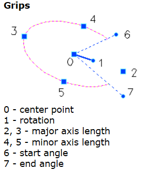
九、Ellipse


 681
681


 被折叠的 条评论
为什么被折叠?
被折叠的 条评论
为什么被折叠?
 到【灌水乐园】发言


