


 本文详细介绍了ASoC架构下Codec驱动的工作原理,包括Codec的注册过程、mfd设备的概念及其在WM8994芯片上的实现、Codec初始化流程及regmap-io机制的应用。
1. Codec简介
在移动设备中,Codec的作用可以归结为4种,分别是:
- 对PCM等信号进行D/A转换,把数字的音频信号转换为模拟信号
- 对Mic、Linein或者其他输入源的模拟信号进行A/D转换,把模拟的声音信号转变CPU能够处理的数字信号
- 对音频通路进行控制,比如播放音乐,收听调频收音机,又或者接听电话时,音频信号在codec内的流通路线是不一样的
- 对音频信号做出相应的处理,例如音量控制,功率放大,EQ控制等等
ASoC对Codec的这些功能都定义好了一些列相应的接口,以方便地对Codec进行控制。ASoC对Codec驱动的一个基本要求是:驱动程序的代码必须要做到平台无关性,以方便同一个Codec的代码不经修改即可用在不同的平台上。以下的讨论基于wolfson的Codec芯片WM8994,kernel的版本3.3.x。
/*****************************************************************************************************/
声明:本博内容均由http://blog.csdn.net/droidphone原创,转载请注明出处,谢谢!
/*****************************************************************************************************/
2. ASoC中对Codec的数据抽象
/* SoC Audio Codec device */
struct snd_soc_codec {
	const char *name;  /* Codec的名字*/
	struct device *dev; /* 指向Codec设备的指针 */
	const struct snd_soc_codec_driver *driver; /* 指向该codec的驱动的指针 */
	struct snd_soc_card *card;    /* 指向Machine驱动的card实例 */
	int num_dai; /* 该Codec数字接口的个数,目前越来越多的Codec带有多个I2S或者是PCM接口 */
	int (*volatile_register)(...);  /* 用于判定某一寄存器是否是volatile */
	int (*readable_register)(...);  /* 用于判定某一寄存器是否可读 */
	int (*writable_register)(...);  /* 用于判定某一寄存器是否可写 */

	/* runtime */
	......
	/* codec IO */
	void *control_data; /* 该指针指向的结构用于对codec的控制,通常和read,write字段联合使用 */
	enum snd_soc_control_type control_type;/* 可以是SND_SOC_SPI,SND_SOC_I2C,SND_SOC_REGMAP中的一种 */
	unsigned int (*read)(struct snd_soc_codec *, unsigned int);  /* 读取Codec寄存器的函数 */
	int (*write)(struct snd_soc_codec *, unsigned int, unsigned int);  /* 写入Codec寄存器的函数 */
	/* dapm */
	struct snd_soc_dapm_context dapm;  /* 用于DAPM控件 */
};
snd_soc_codec_driver:
/* codec driver */
struct snd_soc_codec_driver {
	/* driver ops */
	int (*probe)(struct snd_soc_codec *);  /* codec驱动的probe函数,由snd_soc_instantiate_card回调 */
	int (*remove)(struct snd_soc_codec *);
	int (*suspend)(struct snd_soc_codec *);  /* 电源管理 */
	int (*resume)(struct snd_soc_codec *);  /* 电源管理 */

	/* Default control and setup, added after probe() is run */
	const struct snd_kcontrol_new *controls;  /* 音频控件指针 */
	const struct snd_soc_dapm_widget *dapm_widgets;  /* dapm部件指针 */
	const struct snd_soc_dapm_route *dapm_routes;  /* dapm路由指针 */

	/* codec wide operations */
	int (*set_sysclk)(...);  /* 时钟配置函数 */
	int (*set_pll)(...);  /* 锁相环配置函数 */

	/* codec IO */
	unsigned int (*read)(...);  /* 读取codec寄存器函数 */
	int (*write)(...);  /* 写入codec寄存器函数 */
	int (*volatile_register)(...);  /* 用于判定某一寄存器是否是volatile */
	int (*readable_register)(...);  /* 用于判定某一寄存器是否可读 */
	int (*writable_register)(...);  /* 用于判定某一寄存器是否可写 */

	/* codec bias level */
	int (*set_bias_level)(...);  /* 偏置电压配置函数 */

};/*
* Digital Audio Interface runtime data.
*
* Holds runtime data for a DAI.
*/
struct snd_soc_dai {
const char *name; /* dai的名字 */
struct device *dev; /* 设备指针 */
/* driver ops */
struct snd_soc_dai_driver *driver; /* 指向dai驱动结构的指针 */
/* DAI runtime info */
unsigned int capture_active:1; /* stream is in use */
unsigned int playback_active:1; /* stream is in use */
/* DAI DMA data */
void *playback_dma_data; /* 用于管理playback dma */
void *capture_dma_data; /* 用于管理capture dma */
/* parent platform/codec */
union {
struct snd_soc_platform *platform; /* 如果是cpu dai,指向所绑定的平台 */
struct snd_soc_codec *codec; /* 如果是codec dai指向所绑定的codec */
};
struct snd_soc_card *card; /* 指向Machine驱动中的crad实例 */
};/*
* Digital Audio Interface Driver.
*
* Describes the Digital Audio Interface in terms of its ALSA, DAI and AC97
* operations and capabilities. Codec and platform drivers will register this
* structure for every DAI they have.
*
* This structure covers the clocking, formating and ALSA operations for each
* interface.
*/
struct snd_soc_dai_driver {
/* DAI description */
const char *name; /* dai驱动名字 */
/* DAI driver callbacks */
int (*probe)(struct snd_soc_dai *dai); /* dai驱动的probe函数,由snd_soc_instantiate_card回调 */
int (*remove)(struct snd_soc_dai *dai);
int (*suspend)(struct snd_soc_dai *dai); /* 电源管理 */
int (*resume)(struct snd_soc_dai *dai);
/* ops */
const struct snd_soc_dai_ops *ops; /* 指向本dai的snd_soc_dai_ops结构 */
/* DAI capabilities */
struct snd_soc_pcm_stream capture; /* 描述capture的能力 */
struct snd_soc_pcm_stream playback; /* 描述playback的能力 */
};struct snd_soc_dai_ops {
/*
* DAI clocking configuration, all optional.
* Called by soc_card drivers, normally in their hw_params.
*/
int (*set_sysclk)(...);
int (*set_pll)(...);
int (*set_clkdiv)(...);
/*
* DAI format configuration
* Called by soc_card drivers, normally in their hw_params.
*/
int (*set_fmt)(...);
int (*set_tdm_slot)(...);
int (*set_channel_map)(...);
int (*set_tristate)(...);
/*
* DAI digital mute - optional.
* Called by soc-core to minimise any pops.
*/
int (*digital_mute)(...);
/*
* ALSA PCM audio operations - all optional.
* Called by soc-core during audio PCM operations.
*/
int (*startup)(...);
void (*shutdown)(...);
int (*hw_params)(...);
int (*hw_free)(...);
int (*prepare)(...);
int (*trigger)(...);
/*
* For hardware based FIFO caused delay reporting.
* Optional.
*/
snd_pcm_sframes_t (*delay)(...);
};3. Codec的注册
static struct platform_driver wm8994_codec_driver = {
	.driver = {
		   .name = "wm8994-codec",
		   .owner = THIS_MODULE,
		   },
	.probe = wm8994_probe,
	.remove = __devexit_p(wm8994_remove),
};

module_platform_driver(wm8994_codec_driver);
static int __devinit wm8994_probe(struct platform_device *pdev)
{
	return snd_soc_register_codec(&pdev->dev, &soc_codec_dev_wm8994,
			wm8994_dai, ARRAY_SIZE(wm8994_dai));
}
static struct snd_soc_codec_driver soc_codec_dev_wm8994 = {
	.probe =	wm8994_codec_probe,
	.remove =	wm8994_codec_remove,
	.suspend =	wm8994_suspend,
	.resume =	wm8994_resume,
	.set_bias_level = wm8994_set_bias_level,
	.reg_cache_size	= WM8994_MAX_REGISTER,
	.volatile_register = wm8994_soc_volatile,
};
static struct snd_soc_dai_driver wm8994_dai[] = {
	{
		.name = "wm8994-aif1",
		.id = 1,
		.playback = {
			.stream_name = "AIF1 Playback",
			.channels_min = 1,
			.channels_max = 2,
			.rates = WM8994_RATES,
			.formats = WM8994_FORMATS,
		},
		.capture = {
			.stream_name = "AIF1 Capture",
			.channels_min = 1,
			.channels_max = 2,
			.rates = WM8994_RATES,
			.formats = WM8994_FORMATS,
		 },
		.ops = &wm8994_aif1_dai_ops,
	},
	......
}
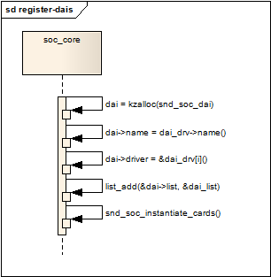
codec = kzalloc(sizeof(struct snd_soc_codec), GFP_KERNEL);
/* create CODEC component name */
codec->name = fmt_single_name(dev, &codec->id); codec->write = codec_drv->write;
codec->read = codec_drv->read;
codec->volatile_register = codec_drv->volatile_register;
codec->readable_register = codec_drv->readable_register;
codec->writable_register = codec_drv->writable_register;
codec->dapm.bias_level = SND_SOC_BIAS_OFF;
codec->dapm.dev = dev;
codec->dapm.codec = codec;
codec->dapm.seq_notifier = codec_drv->seq_notifier;
codec->dapm.stream_event = codec_drv->stream_event;
codec->dev = dev;
codec->driver = codec_drv;
codec->num_dai = num_dai;
	/* register any DAIs */
	if (num_dai) {
		ret = snd_soc_register_dais(dev, dai_drv, num_dai);
		if (ret < 0)
			goto fail;
	}
	list_add(&codec->list, &codec_list);
	snd_soc_instantiate_cards();
4. mfd设备
前面已经提到,codec驱动把自己注册为一个platform driver,那对应的platform device在哪里定义?答案是在以下代码文件中:/drivers/mfd/wm8994-core.c。
WM8994本身具备多种功能,除了codec外,它还有作为LDO和GPIO使用,这几种功能共享一些IO和中断资源,linux为这种设备提供了一套标准的实现方法:mfd设备。其基本思想是为这些功能的公共部分实现一个父设备,以便共享某些系统资源和功能,然后每个子功能实现为它的子设备,这样既共享了资源和代码,又能实现合理的设备层次结构,主要利用到的API就是:mfd_add_devices(),mfd_remove_devices(),mfd_cell_enable(),mfd_cell_disable(),mfd_clone_cell()。
回到wm8994-core.c中,因为WM8994使用I2C进行内部寄存器的存取,它首先注册了一个I2C驱动:
static struct i2c_driver wm8994_i2c_driver = {
	.driver = {
		.name = "wm8994",
		.owner = THIS_MODULE,
		.pm = &wm8994_pm_ops,
		.of_match_table = wm8994_of_match,
	},
	.probe = wm8994_i2c_probe,
	.remove = wm8994_i2c_remove,
	.id_table = wm8994_i2c_id,
};

static int __init wm8994_i2c_init(void)
{
	int ret;

	ret = i2c_add_driver(&wm8994_i2c_driver);
	if (ret != 0)
		pr_err("Failed to register wm8994 I2C driver: %d\n", ret);

	return ret;
}
module_init(wm8994_i2c_init);
static int wm8994_i2c_probe(struct i2c_client *i2c,
			    const struct i2c_device_id *id)
{
	struct wm8994 *wm8994;
	int ret;
	wm8994 = devm_kzalloc(&i2c->dev, sizeof(struct wm8994), GFP_KERNEL);
	i2c_set_clientdata(i2c, wm8994);
	wm8994->dev = &i2c->dev;
	wm8994->irq = i2c->irq;
	wm8994->type = id->driver_data;
	wm8994->regmap = regmap_init_i2c(i2c, &wm8994_base_regmap_config);

	return wm8994_device_init(wm8994, i2c->irq);
}
	/* Add the on-chip regulators first for bootstrapping */
	ret = mfd_add_devices(wm8994->dev, -1,
			      wm8994_regulator_devs,
			      ARRAY_SIZE(wm8994_regulator_devs),
			      NULL, 0);
	if (pdata) {
		wm8994->irq_base = pdata->irq_base;
		wm8994->gpio_base = pdata->gpio_base;

		/* GPIO configuration is only applied if it's non-zero */
		......
	}
	wm8994_irq_init(wm8994);

	ret = mfd_add_devices(wm8994->dev, -1,
			      wm8994_devs, ARRAY_SIZE(wm8994_devs),
			      NULL, 0);
5. Codec初始化
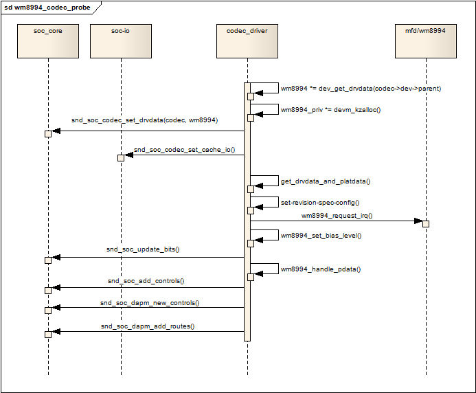
图5.1 wm8994_codec_probe
- 取出父设备的driver_data,其实就是上一节的wm8994结构变量,取出其中的regmap字段,复制到codec的control_data字段中;
- 申请一个wm8994_priv私有数据结构,并把它设为codec设备的driver_data;
- 通过snd_soc_codec_set_cache_io初始化regmap io,完成这一步后,就可以使用API:snd_soc_read(),snd_soc_write()对codec的寄存器进行读写了;
- 把父设备的driver_data(struct wm8994)和platform_data保存到私有结构wm8994_priv中;
- 因为要同时支持3个芯片型号,这里要根据芯片的型号做一些特定的初始化工作;
- 申请必要的几个中断;
- 设置合适的偏置电平;
- 通过snd_soc_update_bits修改某些寄存器;
- 根据父设备的platform_data,完成特定于平台的初始化配置;
- 添加必要的control,dapm部件进而dapm路由信息;
至此,codec驱动的初始化完成。
5. regmap-io
- 为codec定义一个regmap_config结构实例,指定codec寄存器的地址和数据位等信息;
- 根据codec的控制总线类型,调用以下其中一个函数,得到一个指向regmap结构的指针:
- struct regmap *regmap_init_i2c(struct i2c_client *i2c, const struct regmap_config *config);
- struct regmap *regmap_init_spi(struct spi_device *dev, const struct regmap_config *config);
- struct regmap *regmap_init_i2c(struct i2c_client *i2c, const struct regmap_config *config);
- 把获得的regmap结构指针赋值给codec->control_data;
- 调用soc-io的api:snd_soc_codec_set_cache_io使得soc-io和regmap进行关联;


 1585
1585

 被折叠的 条评论
为什么被折叠?
被折叠的 条评论
为什么被折叠?
 到【灌水乐园】发言


