


HDL
A Hardware Description Language (HDL) is a computer language used to describe circuits. A HDL synthesis tool is a computer program that takes a formal description of a circuit written in an HDL as input and generates a netlist that implements the given circuit as output.
HDL,一种描述电路的计算机语言,将HDL中编写的电路描述作为输入,生成网表NetList作为输出。
Verilog and VHDL
Both HDLs are used for test and verification purposes as well as logic synthesis, resulting in a set of synthesizable and a set of non-synthesizable language features.
The main advantages of choosing Verilog or VHDL is the ability to synthesize existing HDL code and to mitigate the requirement for circuit-designers to learn a new language.
Levels
Levels of abstraction,System level,High level,Behavioural level,Register-Transfer Level (RTL),Logical gate level,Physical gate level,Switch level
Levels of abstraction
设计过程 Design process
Digital circuits can be represented at different levels of abstraction. During the design process a circuit is usually first specified using a higher level abstraction. Implementation can then be understood as finding a functionally equivalent representation at a lower abstraction level. When this is done automatically using software, the term synthesis is used.
由高层抽象到低层抽象。
Different levels of abstraction and synthesis
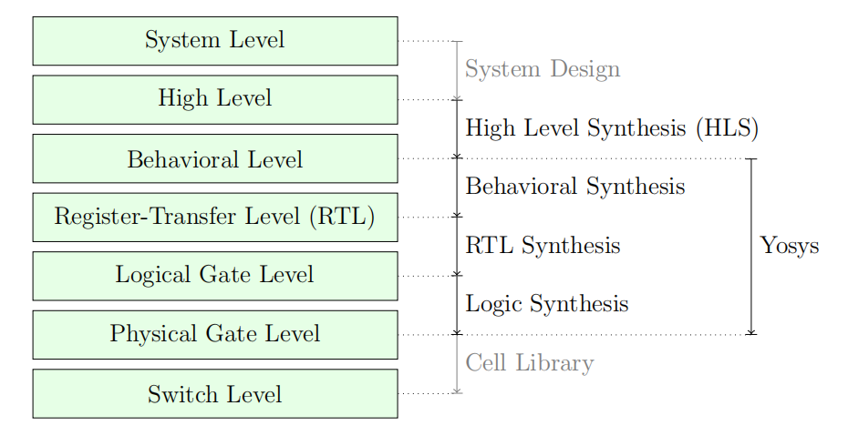
Synthesis is the automatic conversion of a high-level representation of a circuit to a functionally equivalent low-level representation of a circuit.
High level
The high-level abstraction of a system (sometimes referred to as algorithmic level) is also often represented using traditional programming languages, but with a reduced feature set.
EG:C/C++ Code中使用指针进行参数的传递。
Behavioural level
At the behavioural abstraction level a language aimed at hardware description such as Verilog or VHDL is used to describe the circuit, but so-called behavioural modelling is used in at least part of the circuit description. In behavioural modelling there must be a language feature that allows for imperative programming to be used to describe data paths and registers. This is the always-block in Verilog and the process-block in VHDL.
Register-Transfer Level (RTL)
On the Register-Transfer Level the design is represented by combinatorial data paths and registers (usually d-type flip flops).
A design in RTL representation is usually stored using HDLs like Verilog and VHDL. But only a very limited subset of features is used, namely minimalistic always-blocks (Verilog) or process-blocks (VHDL) that model the register type used and unconditional assignments for the datapath logic. The use of HDLs on this level simplifies simulation as no additional tools are required to simulate a design in RTL representation.
NetList
Note that RTL is the first abstraction level in which the circuit is represented as a graph of circuit elements (registers and combinatorial cells) and signals. Such a graph, when encoded as list of cells and connections, is called a netlist.
RTL synthesis is easy as each circuit node element in the netlist can simply be replaced with an equivalent gate-level circuit.
RTL synthesis
However, usually the term RTL synthesis does not only refer to synthesizing an RTL netlist to a gate level netlist but also to performing a number of highly sophisticated optimizations within the RTL representation.
术语RTL synthesis指两方面内容,其一是将RTL网表合成到门级网表,其二是指在RTL表示中执行许多高度复杂的优化。
Logical gate level
At the logical gate level the design is represented by a netlist that uses only cells from a small number of single-bit cells, such as basic logic gates (AND, OR, NOT, XOR, etc.) and registers (usually D-Type Flip-flops).
设计由网表进行表示,设计都是基础逻辑单元的表示。
There are two challenges in logic synthesis: First finding opportunities for optimizations within the gate level netlist and second the optimal (or at least good) mapping of the logic gate netlist to an equivalent netlist of physically available gate types.
逻辑合成的两种方法
The simplest approach to logic synthesis is two-level logic synthesis, where a logic function is converted into a sum-of-products representation, e.g. using a Karnaugh map. This is a simple approach, but has exponential worst-case effort and cannot make efficient use of physical gates other than AND/NAND-, OR/NOR- and NOT-Gates.
Therefore modern logic synthesis tools utilize much more complicated multi-level logic synthesis algorithms. Most of these algorithms convert the logic function to a Binary-Decision-Diagram (BDD) or And-Inverter-Graph (AIG) and work from that representation. The former has the advantage that it has a unique normalized form. The latter has much better worst case performance and is therefore better suited for the synthesis of large logic functions.
Yosys
Yosys is a Verilog HDL synthesis tool. This means that it takes a behavioural design description as input and generates an RTL, logical gate or physical gate level description of the design as output. Yosys’ main strengths are behavioural and RTL synthesis. A wide range of commands (synthesis passes) exist within Yosys that can be used to perform a wide range of synthesis tasks within the domain of behavioural, rtl and logic synthesis.
Features of synthesizable Verilog
Structural Verilog
Structural Verilog (also known as Verilog Netlists) is a Netlist in Verilog syntax.
Expressions in Verilog
Behavioural modelling
Functions and tasks
Verilog supports Functions and Tasks to bundle statements that are used in multiple places (similar to Procedures in imperative programming). Both constructs can be implemented easily by substituting the function/task-call with the body of the function or task.
Conditionals, loops and generate-statements
Arrays and memories
Verilog supports arrays. This is in general a synthesizable language feature. In most cases arrays can be synthesized by generating addressable memories. However, when complex or asynchronous access patterns are used, it is not possible to model an array as memory. In these cases the array must be modelled using individual signals for each word and all accesses to the array must be implemented using large multiplexers.
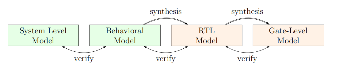
Typical design flow
Green boxes represent manually created models. Orange boxes represent modesl generated by synthesis tools.
Methods from compiler design
Lexing and parsing
A lexer consumes single characters from the input and generates a stream of lexical tokens that consist of a type and a value. The lexer is usually generated by a lexer generator (e.g. flex ) from a description file that is using regular
expressions to specify the text pattern that should match the individual tokens.
Parser
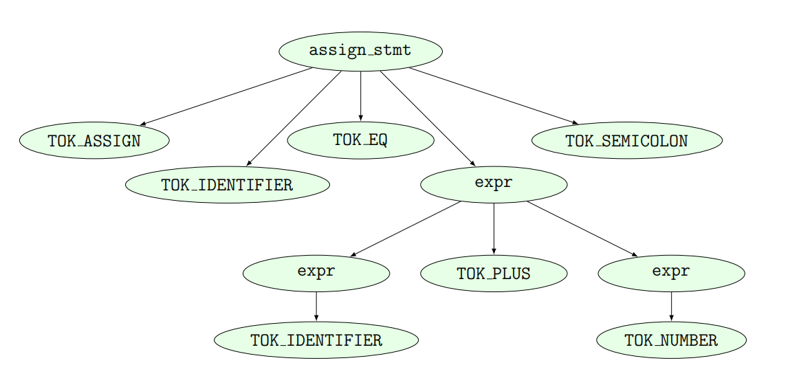
The parser converts the token list to the parse tree in Fig. 2.3. Note that the parse tree never actually exists as a whole as data structure in memory. Instead the parser calls user-specified code snippets (so-called reduce-functions) for all inner nodes of the parse tree in depth-first order.
AST
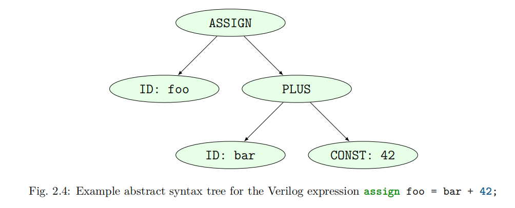
In some very simple applications (e.g. code generation for stack machines) it is possible to perform the task at hand directly in the reduce functions. But usually the reduce functions are only used to build an in-memory data structure with the relevant information from the parse tree. This data structure is called an abstract syntax tree (AST).
Parse tree for the Verilog expression assign foo = bar + 42


 2648
2648


 被折叠的 条评论
为什么被折叠?
被折叠的 条评论
为什么被折叠?
 到【灌水乐园】发言


