


Simple Offset Elimination Technique for Small Capacitance Measurements Using Tweezer-meters
INTRODUCTION
There are three main ways of measuring capacitance: DC charge/discharge, AC Response and Bridge methods. The first method is only applicable to RC while the latter two to LCR measurements.
The first method is implemented by charging and discharging the capacitor with a known current and measing the rate of rise of the resulting voltage; the slower the rate of rise, the larger the capacitance.
The AC Response method to measure capacitance is done by passing a known high-frequency alternating current through the device and recording the resulting voltage across it. From the ratio of these the magnitude of the impedance is calculated. The phase angle between the voltage and current is also measured in combination with the impedance, the equivalent capacitance or inductance, and resistance can be calculated.
More sophisticated instruments use other techniques such as a bridge circuit where the measured component is put in the bridge circuit. By varying the values of the other leg of the bridge the value of the unknown impedance is determined. This indirect method of measuring impedance ensures a very good precision. The bridge usually can also measure parasitic resistance along with capacitance and inductance.
LCR-Reader-MPA offers only the DC charge/discharge and AC response methods. The first method is more efficient in the range from 1 mF to 1 F while the other demonstrates a superb 0.1% basic accuracy for capacitances from 0.1 pF to 1 mF.
A review of methods for measuring a very small capacitance are presented in this publication: “A high precision method for measuring very small capacitance changes,” Ashkan Ashrafi and Hossein Golnabi, Review of Scientific Instruments, Vol. 70, Number 8, August 1999
PRINCIPLE OF OPERATION OF LCR-READER-MPA
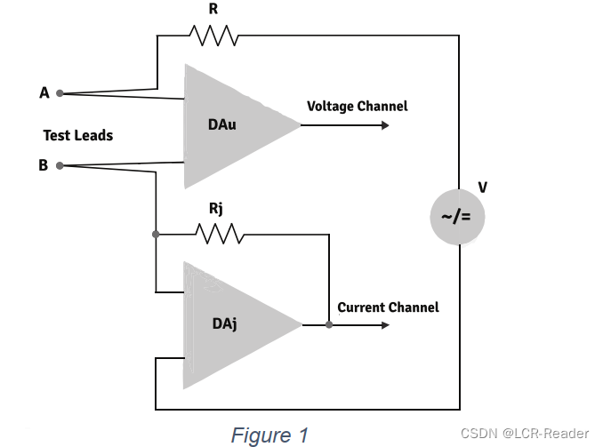
Fig. 1 shows the LCR meter block-diagram. Voltage from the voltage source through a limiting 100 Ω resistor is applied to the DUT connected at points A and B. The amplitude and frequency of the Test Signal V are adjustable. It is also possible to apply either positive or negative DC voltage to the DUT. A voltage drop on the DUT is measured by DAu. The voltage drop on resistor Rj measured by DAj is proportional to the current flowing through the measured component. After digitizing the ADC signals the impedance is calculated according to the formula DUT impedance Z =Rj* Vau/Vaj.
Initial values of Impedance (offsets) obtained during calibration with Open and Short probes are stored in the non-volatile memory of the device and are considered in the calculation of the impedance of the measured component thus eliminating the offsets due to the device internal parasitics.
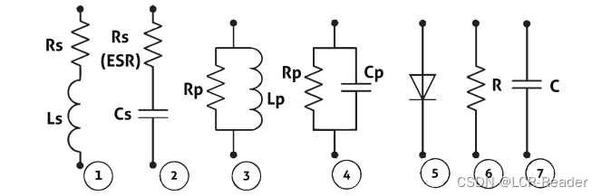
The measured component can be represented as one of the following equivalent circuits:
(1) and (2): AC measurement series circuits, (3) and (4): AC parallel circuits, (5,6,7) DC measurement of diodes, resistance and capacitance.
Impedance in series circuits is Z = Rs + iXs and in parallel circuits is Z = 1/(1/Rp + 1/iXp) where Xs (Xp) < 0 if the reactance is Capacitive and at Xs (Xp) > 0 the reactance is Inductive.
CALCULATION OF PARAMETERS
Capacitance C = 1/(2πf|Xs|) where f is the test frequency. Inductance L = Xs/(2πf). Q = |Xs|/Rs. D = 1/Q.
![]()
In automatic mode the device automatically selects the optimum frequency and the equivalent circuit for measurements. Users can also manually select measurement mode and frequency of the test signal can be selected a range of fixed values from 100 Hz to 100 kHz. Test voltage can be set to 1.0, 0.5 and 0.1 Vrms. By passing direct current through the measured component, the voltage and current can be measured. Using Ω’s law, the DC current Resistance (RDC) is
calculated.
By applying the DC voltage in forward and reverse direction, the diodes are detected, and the polarity of p-n junction is determined.
For capacitors larger than 40 mF the capacitance is calculated using the voltage variation on the measured capacitor when it is charging for a certain time interval and applied current.
The principle of the frequency meter is based on the counting of pulses of the reference generator between the two ramps of the input signal for a certain period of time
(by default about 1 second). At the same time, the quantity of periods of the input signal is counted too. Then the frequency f is calculated by the formula f = M/N*fr where M is the number of periods of the input signal, N is the number of pulses from the reference generator and fr is the frequency of the reference generator.
The principle of measuring the voltage is based on comparing the input signal with the reference voltage.
OFFSET ELIMINATION TECHNIQUE
The Capacitance Offset Calibration Board provides a reliable and accurate method of determining the parasitic offset between the test leads which depends on the distance between them. The dummy PCB uses holes to represent various sizes of components (Fig. 2). This board can be used for evaluation of parasitic capacitance of any tweezer-meter (Smart Tweezers, LCR-Reader or any other tweezer-meter using AC response approach).
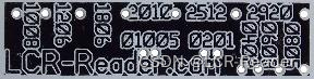
Figure 2
To use the calibration board, place the test leads into the holes corresponding to the size of component under test; make open calibration by pushing the joystick to the right, hold for 2 beeps and release.
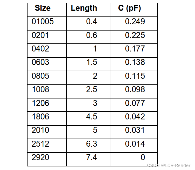
Table below demonstrates dependence of the parasitic capacitance of the tweezers on the distance between the test leads. The measurements were made at 100 kHz. The Open calibration was made at the component size set to 2920 (7.4 mm between the tweezer tips) and therefore the offset is close to zero at this particular component size. It should be noted that the results vary slightly depending on the distance between the tweezer tips even for a fixed component size (varying with the pressure applied to the tweezers) and surroundings around the tweezers. For example, placing a hand near the tweezers may lead to a few fFs change due to a high sensitivity of the device.
After we properly make Open calibration of the device for a specific component size, we may measure the component value with absolute accuracy of about 3 fF.
Appendix A.
LCR-READER-MPA BASIC FUNCTIONS AND FEATURES
Summary of Features
• L-C-R-ESR and LED/Diode Measurements
• AC/DC Voltage/Current Measurements
• Frequency, Pulse Period, Duty Cycle Meter
• Oscilloscope, Signal Generator
• NIST Traceable Calibration Certificate
• Open/Short Calibration
• Component Sorting
• Super Cap Testing
• Optional Bluetooth Module
Technical Specifications
Basic Accuracy: 0.1%
Test Frequency: 100 Hz - 100 kHz
Test Signal Level: 0.1, 0.5, 1.0 Vrms
Measurement Ranges
Resistance R: 5 m to 20 M
Capacitance C: 0.1 pF to 1 F
Inductance L: 1 nH to 100 H
Physical Specifications
Size: 18 x 3 x 1.6 cm
Weight: 1.35 oz.
Battery: 3.7V LiPo
Appendix B.
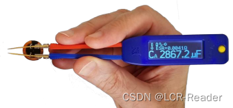
LCR-READER-MPA R-L-C-D MODE SCREEN-SHOT
R-L-C-D mode is the default device mode and it is designated for measurement of Resistors, apacitors, Inductances and Diodes. To select the mode, select R-LC-D in the main menu. In rder to get access to the mode parameters (hidden sub-menu) push the joystick to the right for one beep. A typical screen for R-L-C-D mode looks as follows: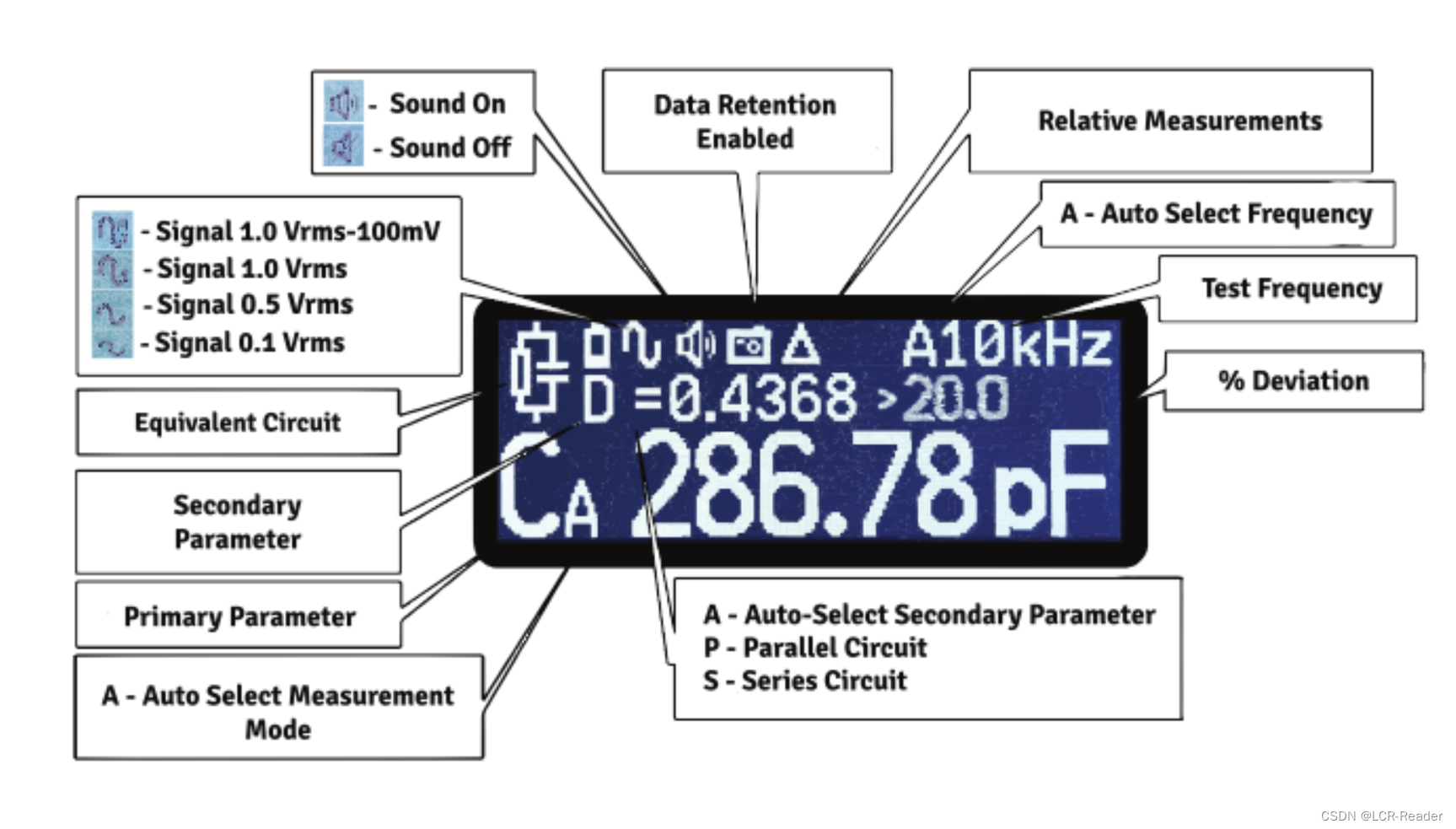


 2万+
2万+


 被折叠的 条评论
为什么被折叠?
被折叠的 条评论
为什么被折叠?
 到【灌水乐园】发言


