


初入STM32的时候跟着视频和纸质资料配置库函数编程环境的时候,都是要什么包括启动文件啊,什么内核文件啊,什么各种各样的支持文件。看的我是云里雾里,其实刚开始学的时候没必要懂这些东西,学着学着就都知道了。以前打开库函数支持包的时候,要在里面挑来挑去,找不到自己要的文件。现在定睛一看,原来它贴心的整好了。
例如
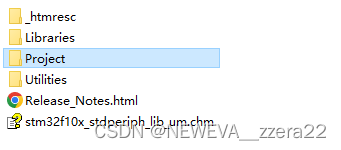
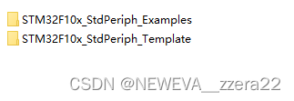
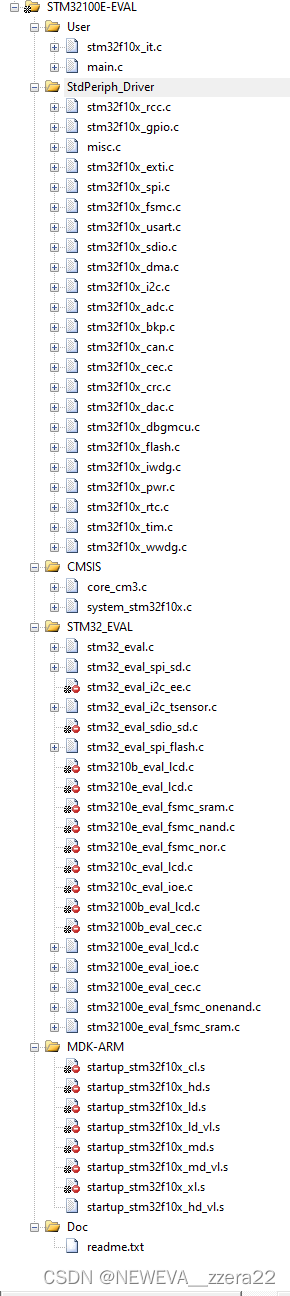
在这个Project里包含两个文件夹,一个是模板,一个是外设使用实例
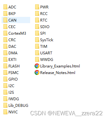
打开外设使用实例,第一个文件夹,可以看到了基本上囊括了所有库文件的使用。
打开GPIO文件

发现了一个文件名叫IO口翻转,另一个叫JTAG重映射,估计就是失能JTAG功能,释放IO口吧。
选择IO口重映射文件夹打开
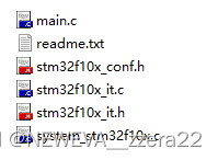
可以看到这里面的所有文件基本都是我们加在工程文件夹User里的文件。
包含了main函数,配置文件,中断服务函数文件,系统初始化文件。
打开main函数会惊奇的发现
*!< At this stage the microcontroller clock setting is already configured,
       this is done through SystemInit() function which is called from startup
       file (startup_stm32f10x_xx.s) before to branch to application main.
       To reconfigure the default setting of SystemInit() function, refer to
       system_stm32f10x.c file
     */

  /* GPIOD Periph clock enable */
  RCC_APB2PeriphClockCmd(RCC_APB2Periph_GPIOD, ENABLE);

  /* Configure PD0 and PD2 in output pushpull mode */
  GPIO_InitStructure.GPIO_Pin = GPIO_Pin_0 | GPIO_Pin_2;
  GPIO_InitStructure.GPIO_Speed = GPIO_Speed_50MHz;
  GPIO_InitStructure.GPIO_Mode = GPIO_Mode_Out_PP;
  GPIO_Init(GPIOD, &GPIO_InitStructure);

  /* To achieve GPIO toggling maximum frequency, the following  sequence is mandatory.
     You can monitor PD0 or PD2 on the scope to measure the output signal.
     If you need to fine tune this frequency, you can add more GPIO set/reset
     cycles to minimize more the infinite loop timing.
     This code needs to be compiled with high speed optimization option.  */
  while (1)
  {
    /* Set PD0 and PD2 */
    GPIOD->BSRR = 0x00000005;
    /* Reset PD0 and PD2 */
    GPIOD->BRR  = 0x00000005;

    /* Set PD0 and PD2 */
    GPIOD->BSRR = 0x00000005;
    /* Reset PD0 and PD2 */
    GPIOD->BRR  = 0x00000005;

    /* Set PD0 and PD2 */
    GPIOD->BSRR = 0x00000005;
    /* Reset PD0 and PD2 */
    GPIOD->BRR  = 0x00000005;

    /* Set PD0 and PD2 */
    GPIOD->BSRR = 0x00000005;
    /* Reset PD0 and PD2 */
    GPIOD->BRR  = 0x00000005;

    /* Set PD0 and PD2 */
    GPIOD->BSRR = 0x00000005;
    /* Reset PD0 and PD2 */
    GPIOD->BRR  = 0x00000005;

    /* Set PD0 and PD2 */
    GPIOD->BSRR = 0x00000005;
    /* Reset PD0 and PD2 */
    GPIOD->BRR  = 0x00000005;

    /* Set PD0 and PD2 */
    GPIOD->BSRR = 0x00000005;
    /* Reset PD0 and PD2 */
    GPIOD->BRR  = 0x00000005;

    /* Set PD0 and PD2 */
    GPIOD->BSRR = 0x00000005;
    /* Reset PD0 and PD2 */
    GPIOD->BRR  = 0x00000005;

    /* Set PD0 and PD2 */
    GPIOD->BSRR = 0x00000005;
    /* Reset PD0 and PD2 */
    GPIOD->BRR  = 0x00000005;

    /* Set PD0 and PD2 */
    GPIOD->BSRR = 0x00000005;
    /* Reset PD0 and PD2 */
    GPIOD->BRR  = 0x00000005;
  }
这不就是以寄存器的方式操作IO口电平吗?
再打开模板文件夹
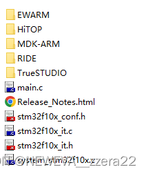
进去MDK-ARM,这个标志很熟悉,keil不就是MDK吗
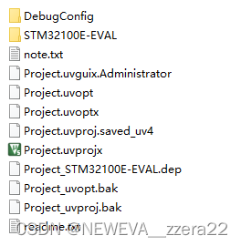
发现了这个工程文件Project,点开
虽然跟咱们平常文件夹命名方式不一样,但是它已经给出了工程必须的几种文件类型
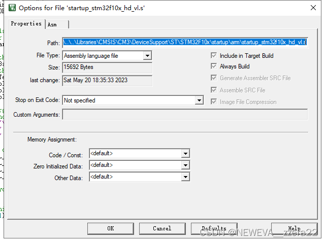
想知道文件路径在哪,鼠标挪到文件上,右键第一个选项,得到了文件路径,哈哈哈


 2578
2578


 被折叠的 条评论
为什么被折叠?
被折叠的 条评论
为什么被折叠?
 到【灌水乐园】发言


