


今天继续学习VxWorks开发板上的2.2寸LCD屏驱动程序。
先来介绍一下开发板上用的2.2寸的LCD屏。
TFT2.2
这里介绍的TFT2.2相关资料,部分来自网页,部分来自@正点原子 的STM32不完全手册寄存器版本_V3.0 文档,在此一并表示感谢。
TFT简介
TFT-LCD 即薄膜晶体管液晶显示器。其英文全称为: Thin Film Transistor-Liquid Crystal Display。 TFT-LCD 与无源 TN-LCD、 STN-LCD 的简单矩阵不同,它在液晶显示屏的每一个象素上都设置有一个薄膜晶体管( TFT),可有效地克服非选通时的串扰,使显示液晶屏的静态特性与扫描线数无关,因此大大提高了图像质量。 TFT-LCD 也被叫做真彩液晶显示器。
2.2寸LCD实物图
先来看看开发板上所带LCD屏外观,上实物图:
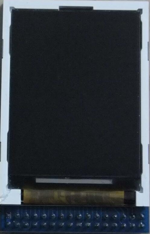
然而并没有多美观。此2.2寸TFT液晶屏,分辨率为240*320,高320像素,宽240像素。
原理图
再来看看这个LCD显示屏和开发板接口的原理图:
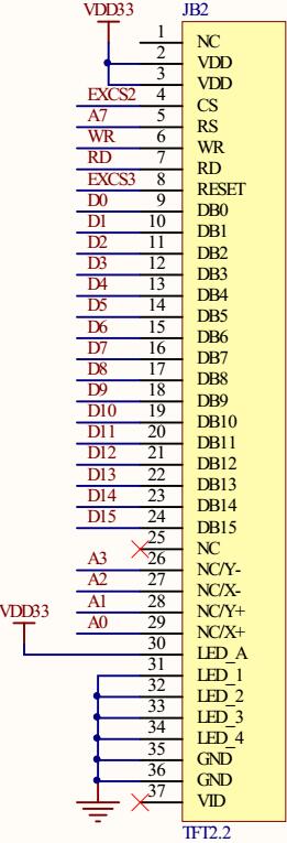
其中 有
DB0-DB15 共16位数据线
X+,X-,Y+,Y- 四个坐标信号线
RESEST
RD
WR
CS
RS
VDD、GND 电源
再看看这些引脚与S3C2410的连接:(与2410的连接,地址线中,实际用到的,只有A0-A3, A7)
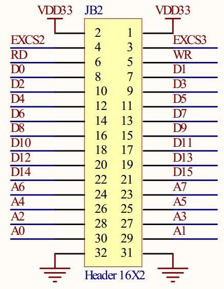
这是这块开发板上的系统总线通过JB2的32针接口扩展。总共包含16条数据线(D0-D15),8条地址线(A0-A7)、还有一些控制信号线(片选、读写、复位等),同时JB2可以向外提供3.3V电压输出。而实际应用中很少有用户通过总线扩展外设。
此开发板通过这个总线外接2.2寸TFT液晶屏。可以看到LCD2.2显示屏总共引出32根口线,其中
- D0-D15 共16位数据线
- A0-A7 共8位地址线
- RD 读信号
- WR 写信号
- EXCS2 外部片选2
- EXCS3 外部片选3
- VDD33 x 2
- GND x 2
除去4位电源线,现在再来看看,剩下的信号线的实际连接,先来看看 数据线:
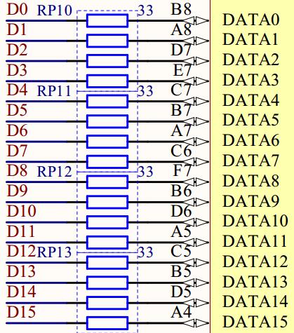
很清晰,16位数据线直接通过排阻拉到了S3C2410的DATA[15:0]数据总线上。
再看看地址线:
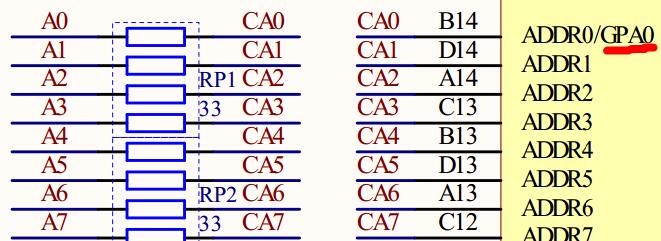
也是很直接地通过排阻接到S3C2410的 ADDR[7:0]地址总线上。
再来看 EXCS2和EXCS3 两个外部片选信号的连接:
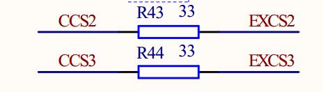
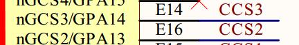
可以看到,此处的两个外部片选信号通过两个电阻直接接到了 S3C2410的 GPA13、GPA14两个位上,这两个口线均可复用作片选信号:nGCS2 、nGCS3
由上可知 nGCS2 接了LCD2.2的片选信号,nGCS3接了LCD2.2的复位信号。
最后来看看,读写控制信号:

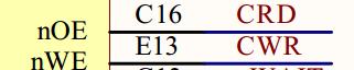
读写信号直接通过电阻接到 S3C2410的 nOE、nWE 上了。
TFTLCD 驱动芯片
有了TFTLCD硬件模块,还得有相应的驱动芯片才行。常见的型号众多:ILI9341/ILI9325/RM68042/RM68021/ILI9320/ILI9328/LGDP4531/LGDP4535/SPFD5408/SSD1289/1505/B505/C505/NT35310/NT35510 等。
本开发板上用的是 ILI9320DS,接下来先简单了解一下 ILI9320DS。
ILI9320
{关于ILI9320的操作,请直接学习datasheet和相关的网站,@正点原子 讲STM32的教程里面也对ILI系列的操作非常清晰,可查阅相关资料,此处暂时略去,回头再来学习}
驱动程序学习
此处再来回顾一下开发板的2410与TFT驱动ILI9320的连接:
| S3C2410 | ILI9320 |
|---|---|
| nGCS2/GPA13 | CS |
| nGCS3/GPA14 | RESET |
| nOE | RD |
| nWR | WR |
| ADDR7 | RS |
| ADDR0/GPA0 | X+ |
| ADDR1 | Y+ |
| ADDR2 | X- |
| ADDR3 | Y- |
| DATA0-DATA15 | DB0-DB15 |
这是一种典型的总线扩展方式,具体不会的,此处暂以红色标记,回头再来学习。
下面开始来学习驱动代码:
#define LCD22_COM_BASE  (0X10000000) //CS2
#define LCD22_DATA_BASE (0X10000080)
先看看S3C2410复位后的存储器映射:
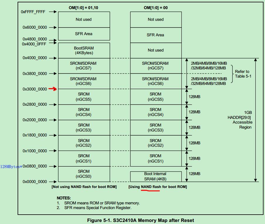
可以看到, nGCS2 所指向的SROM区首地址为 0x1000_0000,也就是总线扩展出来驱动LCD驱动芯片的基地址了。但 LCD22_DATA_BASE 宏为什么是在此基础上偏移8*16 = 128个字节,此时还不懂,待学习。
接下来几个函数简单,边看边注释,
void delayms(int count)     // X1ms
{
    int i,j;
    for(i=0;i<count;i++)
        for(j=0;j<100;j++);
}

void Lcd_Write_Com(UINT16 com)       // 发送命令
{
    *(volatile UINT16 *)LCD22_COM_BASE = com;    // 直接往 0x1000_0000 写数据
}

void Lcd_Write_Data(UINT16 data)     // 发送数据
{
    *(volatile UINT16 *)LCD22_DATA_BASE = data;  // 0x1000_0080 **地址是为何?
}

void Lcd_Write_Com_Data(UINT16 com,UINT16 val)   // 发送数据命令
{
    Lcd_Write_Com(com);
    Lcd_Write_Data(val);
}
此处的 Lcd_Write_Com_Data 函数先写命令,再写数据,实现S3C2410向ILI9320发送命令字控制显示的作用。
// 函数名称:Address_set
// 函数功能:设置起始点位置,可以理解为绘图开窗
void Address_set(UINT16 x1,UINT16 y1,UINT16 x2,UINT16 y2)
{
    Lcd_Write_Com(0x0020);Lcd_Write_Data(x1);   // 设置X坐标位置
    Lcd_Write_Com(0x0021);Lcd_Write_Data(y1);   // 设置Y坐标位置
    Lcd_Write_Com(0x0050);Lcd_Write_Data(x1);   // 设置X开始
    Lcd_Write_Com(0x0052);Lcd_Write_Data(y1);   // 设置Y开始
    Lcd_Write_Com(0x0051);Lcd_Write_Data(x2);   // 设置X结束
    Lcd_Write_Com(0x0053);Lcd_Write_Data(y2);   // 设置Y结束
    Lcd_Write_Com(0x0022);
}
这个 Address_set 函数设置相关位置,就不得不提一下ILI9320的指令描述了。直接看datasheet 上的表格:
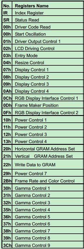
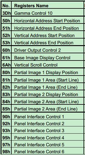
具体到每条指令的值如何设置,作用是何就要自己查阅datasheet了。此节只对用到的几条指令做简单讲解。
| 指令 | 作用 |
|---|---|
| 20h | Horizontal GRAM Address Set |
| 21h | Vertical GRAM Address Set |
| 50h | Horizontal Address Start Position |
| 52h | Vertical Address Start Position |
| 51h | Horizontal Address End Position |
| 53h | Vertical Address End Position |
| 22h | Write Data to GRAM |
从表格来看和上面代码中的中文注释是一致的。
接下来是LCD2.2初始化函数,这个函数非常重要:
void Lcd22_Init(void)
{
UINT32 dwValReg;
// GPA[14]: 0=Output, 1=nGCS3
SNGS3C_REG_READ( rGPACON, dwValReg );
dwValReg = dwValReg & (~(1<<14));
SNGS3C_REG_WRITE( rGPACON, dwValReg ); // 配置GPA[14]为普通输出,控制TFT2.2的复位信号
// 连续复位TFT2.2两次, ILI9320需要上电复位,低电平复位
*(volatile UINT32 *)rGPADAT |=(1<<14);
taskDelay(1);
*(volatile UINT32 *)rGPADAT &=~(1<<14); // 复位
taskDelay(1);
*(volatile UINT32 *)rGPADAT |=(1<<14);
taskDelay(1);
Lcd_Write_Com_Data(0x0000, 0x0001); // Start internal OSC.
Lcd_Write_Com_Data(0x0001, 0x0100); // set SS and SM bit
Lcd_Write_Com_Data(0x0002, 0x0700); // set 1 line inversion
Lcd_Write_Com_Data(0x0003, 0x0030); // set GRAM write direction and BGR=1.
Lcd_Write_Com_Data(0x0004, 0x0000); // Resize register
Lcd_Write_Com_Data(0x0008, 0x0207); // set the back porch and front porch
Lcd_Write_Com_Data(0x0009, 0x0000); // set non-display area refresh cycle ISC[3:0]
Lcd_Write_Com_Data(0x000A, 0x0000); // FMARK function
Lcd_Write_Com_Data(0x000C, 0x0000); // RGB interface setting
Lcd_Write_Com_Data(0x000D, 0x0000); // Frame marker Position
Lcd_Write_Com_Data(0x000F, 0x0000); // RGB interface polarity
// power on sequence
Lcd_Write_Com_Data(0x0010, 0x0000); // SAP, BT[3:0], AP, DSTB, SLP, STB
Lcd_Write_Com_Data(0x0011, 0x0000); // DC1[2:0], DC0[2:0], VC[2:0]
Lcd_Write_Com_Data(0x0012, 0x0000); // VREG1OUT voltage
Lcd_Write_Com_Data(0x0013, 0x0000); // VDV[4:0] for VCOM amplitude
delayms(20); // Dis-charge capacitor power voltage
Lcd_Write_Com_Data(0x0010, 0x1590); // SAP, BT[3:0], AP, DSTB, SLP, STB
Lcd_Write_Com_Data(0x0011, 0x0007); // DC1[2:0], DC0[2:0], VC[2:0]
delayms(20); // Delay 50ms
Lcd_Write_Com_Data(0x0012, 0x013A); // VREG1OUT voltage
delayms(20); // Delay 50ms
Lcd_Write_Com_Data(0x0013, 0x1500); // VDV[4:0] for VCOM amplitude
Lcd_Write_Com_Data(0x0029, 0x0000); // VCM[4:0] for VCOMH
delayms(20);
Lcd_Write_Com_Data(0x0020, 0x0000); // GRAM horizontal Address
Lcd_Write_Com_Data(0x0021, 0x0000); // GRAM Vertical Address
// Adjust the Gamma Curve
Lcd_Write_Com_Data(0x0030, 0x0000);
Lcd_Write_Com_Data(0x0031, 0x0707);
Lcd_Write_Com_Data(0x0032, 0x0700);
Lcd_Write_Com_Data(0x0035, 0x0004);
Lcd_Write_Com_Data(0x0036, 0x1f00);
Lcd_Write_Com_Data(0x0037, 0x0004);
Lcd_Write_Com_Data(0x0039, 0x0007);
Lcd_Write_Com_Data(0x003C, 0x0400);
Lcd_Write_Com_Data(0x003D, 0x1f00);
Lcd_Write_Com_Data(0x0050, 0x0000); // Horizontal GRAM Start Address
Lcd_Write_Com_Data(0x0051, 0x00EF); // Horizontal GRAM End Address
Lcd_Write_Com_Data(0x0052, 0x0000); // Vertical GRAM Start Address
Lcd_Write_Com_Data(0x0053, 0x013F); // Vertical GRAM Start Address
Lcd_Write_Com_Data(0x0060, 0x2700); // Gate Scan Line
Lcd_Write_Com_Data(0x0061, 0x0001); // NDL,VLE, REV
Lcd_Write_Com_Data(0x006A, 0x0000); // set scrolling line
// Partial Display Control
Lcd_Write_Com_Data(0x0080, 0x0000);
Lcd_Write_Com_Data(0x0081, 0x0000);
Lcd_Write_Com_Data(0x0082, 0x0000);
Lcd_Write_Com_Data(0x0083, 0x0000);
Lcd_Write_Com_Data(0x0084, 0x0000);
Lcd_Write_Com_Data(0x0085, 0x0000);
// Panel Control
Lcd_Write_Com_Data(0x0090, 0x0013);
Lcd_Write_Com_Data(0x0092, 0x0000);
Lcd_Write_Com_Data(0x0093, 0x0003);
Lcd_Write_Com_Data(0x0095, 0x0110);
Lcd_Write_Com_Data(0x0097, 0x0000);
Lcd_Write_Com_Data(0x0098, 0x0000);
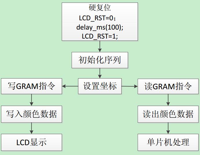
Lcd_Write_Com_Data(0x0007, 0x0173);
}这个函数就不再具体分析,全部是对TFT2.2写指令数据,可以参照@正点原子的TFTLCD模块使用流程图:
接下来看看再个非常实际的驱动函数:
// 函数名称: Pant
// 函数功能: 整屏写入数据
void Pant(UINT16 data)
{
    int i,j;

    Address_set(0,0,240,320);    // 设置开始和结束点的位置,以像素为单位,宽240p,高320p

    for(i=0; i<320; i++)
    {
        for(j=0; j<240; j++)
        {
            Lcd_Write_Data(data);  // 挨个像素点,整屏全部写入参数数据,初始化的时候设置好参数,可以自动扫描(地址指针自动加)
        }
    }
}
// 函数名称:Lcd22DispPicture
// 函数功能:在TFT2.2寸显示屏指定开窗区域显示图片
void Lcd22DispPicture(UINT16 x1,UINT16 y1,UINT16 x2,UINT16 y2,char* DispBuf)
{
int j;
UINT16 dispdata;
Address_set(x1,y1,x2,y2); // 开窗左上角(x1,y1),右下角(x2,y2)
for (j=0;j<(x2-x1)*(y2-y1);j++)
{
dispdata=DispBuf[j*2+1];
dispdata=(dispdata<<8)|DispBuf[j*2];
Lcd_Write_Data(dispdata); // 挨个像素点写入16位的图像数据
}
}
// 其中,图片数据 DispBuf 组织格式为:两个char元素为一个像素点数据
// 其中前一个字节为高8位,后一个字节为低8位有了上面这个开窗绘图函数 Lcd22DispPicture,还需要为其组织图片数据,也就是下面这个函数了:
// 函数名称:WriteLcd22Buf
// 函数功能:由文件名读出图片数据组织为可以直接写入到ILI9320的格式数组buf里面
int WriteLcd22Buf(char* FileName,char* DispBuf)
{
    int iFileSize;
    int fd;

    iFileSize = 0;
    fd = open(FileName, O_RDONLY, 0);    // VxWorks 系统API函数
    if(ERROR == fd)
    {
        return ERROR;
    }

    iFileSize = read(fd, (DispBuf + iFileSize), 200*1024);
    if(ERROR == iFileSize)
    {
        printf("Failed to read the file! return!\n");
        close(fd);
        return ERROR;
    }

    close(fd);
    return iFileSize;
}
这个函数也没有什么好说的,直接打开文件并读取文件数据到 DispBuf中,这可以证明原始的图片文件就已经是满足要求格式(两个字节一个像素点,前一个字节高8位,后一个字节低8位)的文件。
但此处要讲的是VxWorks的两个API函数 open, read.
VxWorks API — open, read
打开VxWorks的API参考手册(file:///D:/Tornado2.2/docs/VxWorks_API_Reference.htm),进入到 OS Library中,找到I字母打头的库,可以看到I/O interface library库—— ioLib,该IO接口库包含了以下函数:
ROUTINES:
creat( ) - create a file
open( ) - open a file
unlink( ) - delete a file (POSIX)
remove( ) - remove a file (ANSI)
close( ) - close a file
rename( ) - change the name of a file
read( ) - read bytes from a file or device
write( ) - write bytes to a file
ioctl( ) - perform an I/O control function
lseek( ) - set a file read/write pointer
ioDefPathSet( ) - set the current default path
ioDefPathGet( ) - get the current default path
chdir( ) - set the current default path
getcwd( ) - get the current default path (POSIX)
getwd( ) - get the current default path
ioGlobalStdSet( ) - set the file descriptor for global standard input/output/error
ioGlobalStdGet( ) - get the file descriptor for global standard input/output/error
ioTaskStdSet( ) - set the file descriptor for task standard input/output/error
ioTaskStdGet( ) - get the file descriptor for task standard input/output/error
isatty( ) - return whether the underlying driver is a tty device
ioLib总共包含20个函数,可以分为以下四类:
- 7个基本驱动:create(), remove(), open(), close(), read(), write(), ioctl()
- 文件系统功能:rename(), lseek()
- 设置或获取当前工作目录:ioDefPathSet(), ioDefPathGet(), chdir(), getcwd(), getwd()
- 指派任务和全局标准文件描述符:ioTaskStdSet(), ioTaskStdGet(), ioGlobalStdSet(), ioGlobalStdGet()
- isatty():判断基础驱动是否是一个tty设备
在VxWorks中,基本的IO层,用一个小的整数(文件描述符)来描述文件,通常是一个由open()或create()返回的值。
三个保留的文件描述符:
- 0 (STD_IN)
- 1 (STD_OUT)
- 2 (STD_ERR)
用到IO库里面的文件(比如此处的 open(), read())时均需要包含头文件 ioLib.h
open
SYNOPSIS
int open
    (
        const char* name,
        int         flags,  /* O_RDONLY, O_WRONLY, O_RDWR, or O_CREAT */
        int         mode    /* mode of file to create(UNIT chmod style) */
    )
通常,open()只能打开存在的设备或文件,然而NFS网络设备也可以通过open()函数来创建,例子:
fd = open("/usr/myFile", O_CREAT | O_RDWR, 0644);当然也只有NFS驱动使用这个mode参数。
RETURNS
A file descriptor number, or ERROR if a file name is not specified, the device does not exist, no file descriptors are available, or the driver returns ERROR.
ERRNO
ELOOP
read
NAME
read() - - - read bytes from a file or device
SYNOPSIS
int read
    (
        int    fd,       /* file descriptor from which to read */
        char * buffer,   /* pointer to buffer to receive bytes */
        size_t maxbytes  /* max no. of bytes to read into buffer */
    )
read函数从fd读取最多maxbytes的数据到buffer,实际会调用底层设备驱动来工作。
RETURNS
The number of bytes read (between 1 and maxbytes, 0 if end of file), or ERROR if the file descriptor does not exist, the driver does not have a read routines, or the driver returns ERROR. If the driver does not have a read routine, errno is set to ENOTSUP.
函数返回读取到的实际数据字节数(1<= returns <= maxbytes),遇到文件结束就返回0;若底层驱动没有读取函数,则置错误号 errno 为 ENOTSUP.
TFTLCD2.2寸液晶屏的驱动程序到此基本结束,再来看看向外部提供的任务接口函数:
//2*240*320=153600, 定义一个全局的缓存用来存储整屏数据,按前分析,大小应两倍于像素点个数
unsigned char Lcd22DispBuf[153600];

// 函数名称:Lcd_Main
// 函数功能:界面显示处理主函数
int Lcd_Main(void)
{
    UINT16   dispdata;
    int      i, j, k;

    Lcd22_Init();          // TFT LCD 初始化
    taskDelay(1);

    Pant(0xffff);           // 清屏
    Pant(0xf800);           // 红屏
    taskDelay(120);
    Pant(0x07E0);           // 绿屏
    taskDelay(120);
    Pant(0x001f);           // 蓝屏
    taskDelay(120);

    i = 0;
    while(1)
    {
        if(4 == MenuDisp)   // 一个全局变量指示进入图片测试界面
        {
            i++;
            switch(i)
            {
            case 1: WriteLcd22Buf("/C/butterfly240.bin", Lcd22DispBuf); break;
            case 2: WriteLcd22Buf("/C/butterfly240.bin", Lcd22DispBuf); break;
            case 3: WriteLcd22Buf("/C/butterfly240.bin", Lcd22DispBuf); break;
            case 4: WriteLcd22Buf("/C/butterfly240.bin", Lcd22DispBuf); break;
            case 5: WriteLcd22Buf("/C/butterfly240.bin", Lcd22DispBuf); break;
            case 6: WriteLcd22Buf("/C/butterfly240.bin", Lcd22DispBuf); break;
            case 7: WriteLcd22Buf("/C/butterfly240.bin", Lcd22DispBuf); break;
            case 8: WriteLcd22Buf("/C/butterfly240.bin", Lcd22DispBuf); break;
            }

            i %= 9;
            Lcd22DispPicture(0,0,240,240,Lcd22DispBuf);   // 开窗绘图
            taskDelay(120);                               // 延时让出CPU
        }
        else // 退出图片界面
        {
            i = 0;
            WriteLcd22Buf("/C/RK2410-240.bin", Lcd22DispBuf);
            Lcd22DispPicture(0,0,240,240,Lcd22DispBuf);   // 显示标准LOGO界面
            taskDelay(10);
        }
    }
}
好了,开发板的LCD2.2寸液晶屏驱动程序就学习到这里,可以看到,除了LCD2.2屏驱动芯片ILI9320的驱动程序还需要仔细学习外,应用上驱动一个LCD屏还是比较容易的。
以上代码几乎全部来自Rock,若有侵权,请联系我删除,谢谢!


 3517
3517


 被折叠的 条评论
为什么被折叠?
被折叠的 条评论
为什么被折叠?
 到【灌水乐园】发言


